 Lucy Fauth
When I started this project I already had some concerns that the HV583 driver might not be suitable for driving 128 ultrasonic transducers. However for some reason I kept rather optimistic that all would work out fine in the end. I did some test before, and the signals weren't too bad. Also, driving piezos is one of the recommended applications for this IC...
Well, this week I finally managed to test the performance of my array. The pcbs for the transducers arrived and I started assembling 32 of them to the pcb for testing.
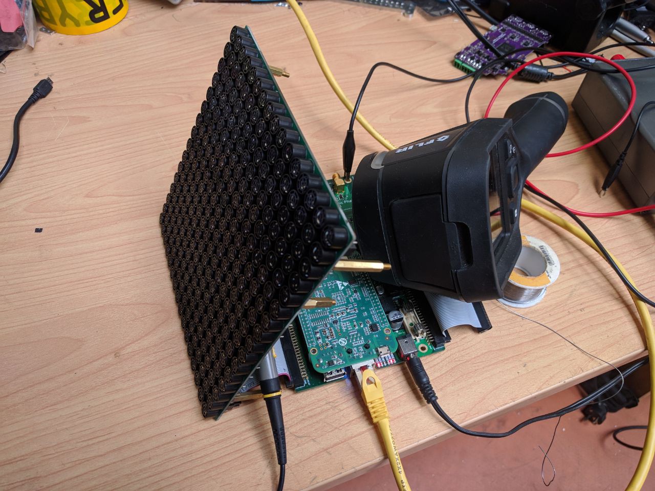
All transducers received the same 40kHz square signal, because I only cared for the power consumption and temperature at this point. I supplied the HV583 from an external power supply, just to make sure...
I glued on a heatsink after I realized there is no way for this to work without one, and set the onboard fan to full speed. Unfortunately, even with only 1/4 of the load and not eve full input voltage, the heatsink quickly reached 110°C. The die temperature is probably >160°C at this point.
Here is a (quite shaky) video of this first test:
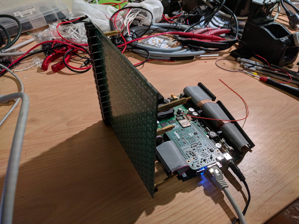
I then assembled all transducers, because, well, I don't have anything else to do with them and they were laying around. Also, a possible future attempt would probably based on the same connectors and board shape, so I can recycle the transducer array.
At least it looks quite nice...
With all transducers in place, I can only turn up the voltage to 24V before the driver passes out because of over temperature. The effective transducer voltage is 15Vpp. My 2nd array is working at 20-30Vpp...
There are multiple options now to continue this project. One might be to improve cooling, however I don't think that's worth a try.
The other option would be to use the HV582. This driver only has 96 output channels, so I would need three of them for one 16x16 array. Or two, and make it 14x14. In both cases, I would need a new mainboard, as they are unfortunately not pin compatible. On the first look the pinout seems quite identical, unfortunately Microchip decided to swap VDD and GND on these two chips...
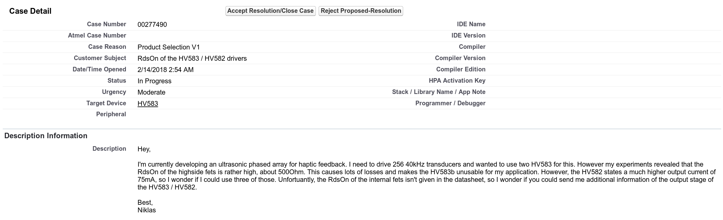
According to the datasheet, this chip can supply 75mA peak instead of 30mA, so it might work somewhat better because the losses in the output stages are less. Also the power is spread to three instead of two packages.
I contacted Microchip to get more details about the RDSon of the HV582 compared to the HV583 to estimate if the HV582 is sufficient for my application. Unfortunately, after more than two month of rather pointless emails the were not willing to give me this information if I'm not asking as a "professional engineering firm".
I'm currently not willing to invest time and another 100$ for new pcbs for the HV582 without this information. So unfortunately, this project is on hold until Microchip decides that this project is worth it to take a quick look at the internal parameters of their design. I was not able to get anyone to do this. But maybe someone from here knows someone who can?...
UPDATE: Microchip replied! They gave me exactly the information I was looking for. Thanks to every one who helped with this shout-out.
The HV582 looks promising, the better performance might be all I need to get it properly working. However, for now I'm designing a new transducer board with a npn / pnp complementary driver stage under each transducer. This allows me to recycle the driver board with the two HV583. I'm currently designing the pcb (luckily this is only a two layer board, so it's quite cheap), so stay tuned!
Discussions
Become a Hackaday.io Member
Create an account to leave a comment. Already have an account? Log In.
Hi,
May I bother you few minutes and allow me to introduce myself ? My name is Steven, I am from Guangzhou China. I am currently doing a project of a flat 8*8 structure Ultrasonic Array. However, there are some problems I do not know how to solve.
During test 1, a diameter of 4mm Styrofoam was successfully levitated for approximately 20 seconds, then it fell off. Based on this, I made some notes and write down couple questions.
Notes:
1. I have spent 10 minutes locating the 'foci point' by adjusting the Green dot on AcousticField 3d software. The actual 'foci point (levitated point)' was not 3/4cm above the array, it was more like 9cm in my case.
2. Tested object (3-4mm Styrofoam) was successfully levitated. However, the levitation was not stable at all. The tested object was 'jumping' up and down.
3. As suggested from Dr. Asier Marzo, testing voltage and current were set to 15volts and 0.7A respectively. The actual reading of Current normally just reaches 0.176A (Assumed all transducers are operating properly)
4. The Ultrasonic Array is making very high-pitch noise every single time I turn it on and connect it with the power supply.
5. In the day 2 of testing, the 'foci point' was failed to be located, the Styrofoam was 'pushed' up by transducers, then dropped out from the ultrasonic array.
6. Failed to levitate after test 1.
Questions:
1. Why is it hard to locate 'foci point' in my case ?
2. Are there only one 'foci point' that we can find from this Flat 8x8 structure ?
3. From Dr. Asier Marzo 's YouTube video, the levitation is very stable and persistent. For mine, the longest levitation time was less than 20 seconds. What kind of mistakes could I potentially make / what errors could it be ?
4. Is it normal that the Ultrasonic Array makes high-pitch noise when it is operating ?
please do not hesitate to contact me if you are interested in my progress, and I will be super appreciated if you would like to help me and give me some guidance.
My personal email address is chenzicong18@outlook.com
kindest regards,
Steven chan
Are you sure? yes | no
I wonder if the Siemens demo board would be any good to you.
https://hackaday.com/2018/07/24/open-source-power-converter-for-the-masses/
https://tapas.ideas.aha.io/ideas
Or alternatively silicon carbide based devices?l.
Are you sure? yes | no
Thanks a lot!
This is exactly what I was looking for :3
I knew that this chips weren't meant to drive ultrasonic transducers, however I still think they are quite suitable for this application. The HV582 looks promising, the better performance might be all I need to get it properly working. However, for now I'm designing a new transducer board with a npn / pnp complementary driver stage under each transducer. This allows me to recycle the driver board with the two HV583.
Are you sure? yes | no
Hi,
The HV582 and HV583 are targeted at driving piezo loads in the ink-jet driver market. I never heard of them being used in the ultrasound area. Both parts have 2 output transistors, P-channel pulls Vout high, N-channel pulls Vout low.
The HV852 has Ron of 133 ohm max, measured at 75ma. It's max current is 75ma. N and P channel have same spec.
The HV853 has Ron for the P-ch of 466 ohm, max at 15ma, N-ch of 400 ohm, at 15ma. Max current is 30ma.
These devices are not expected to be running at a 100% duty cycle. Depending on piezo load you can easliy be having thermal issues.
Hope this helps, Andy
andysabol@comcast.net
Are you sure? yes | no