Close
0%
0%

Arduino Nano QP

The Arduino Nano Quick Project. Develop Everywhere.

Similar projects worth following
The Arduino Nano Quick Project. It's a small board, based on an Arduino Nano. It has buttons, a display and I/O ports on it so that it's ready for most of your small Projects

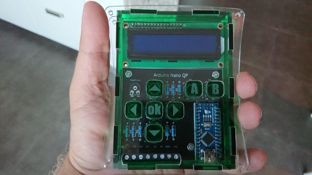
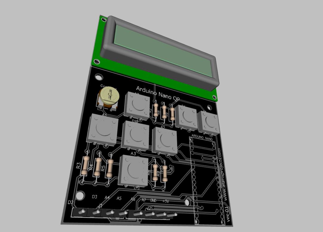
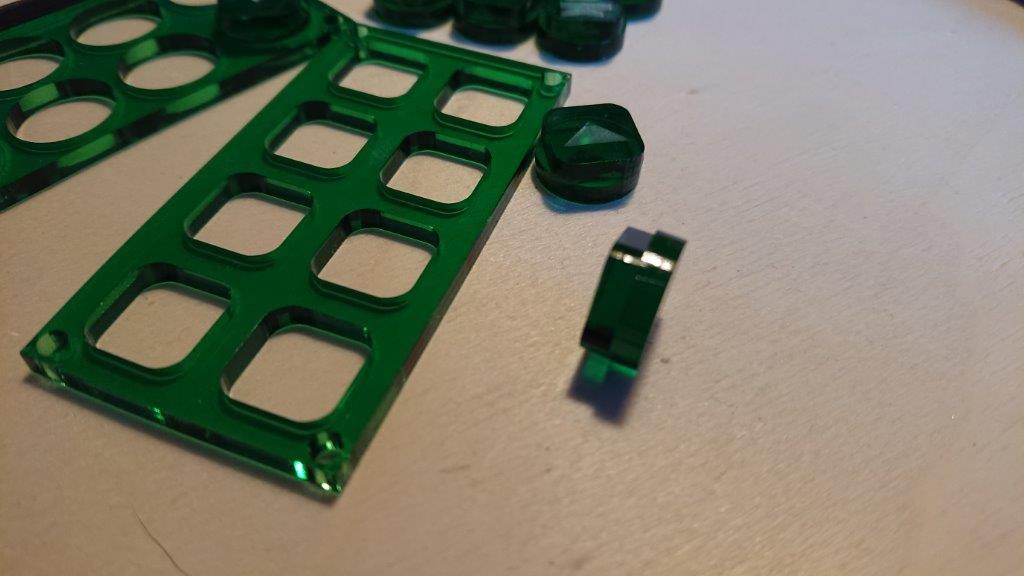
Do you also have the occasional problem, that you want to create something with an Arduino, but the workshop is a mess, you find neither a suitable display nor the right button, and finally, if you have everything together, you lost the desire, to realize the idea. That's why I have developed the Arduino Nano Quick Project.

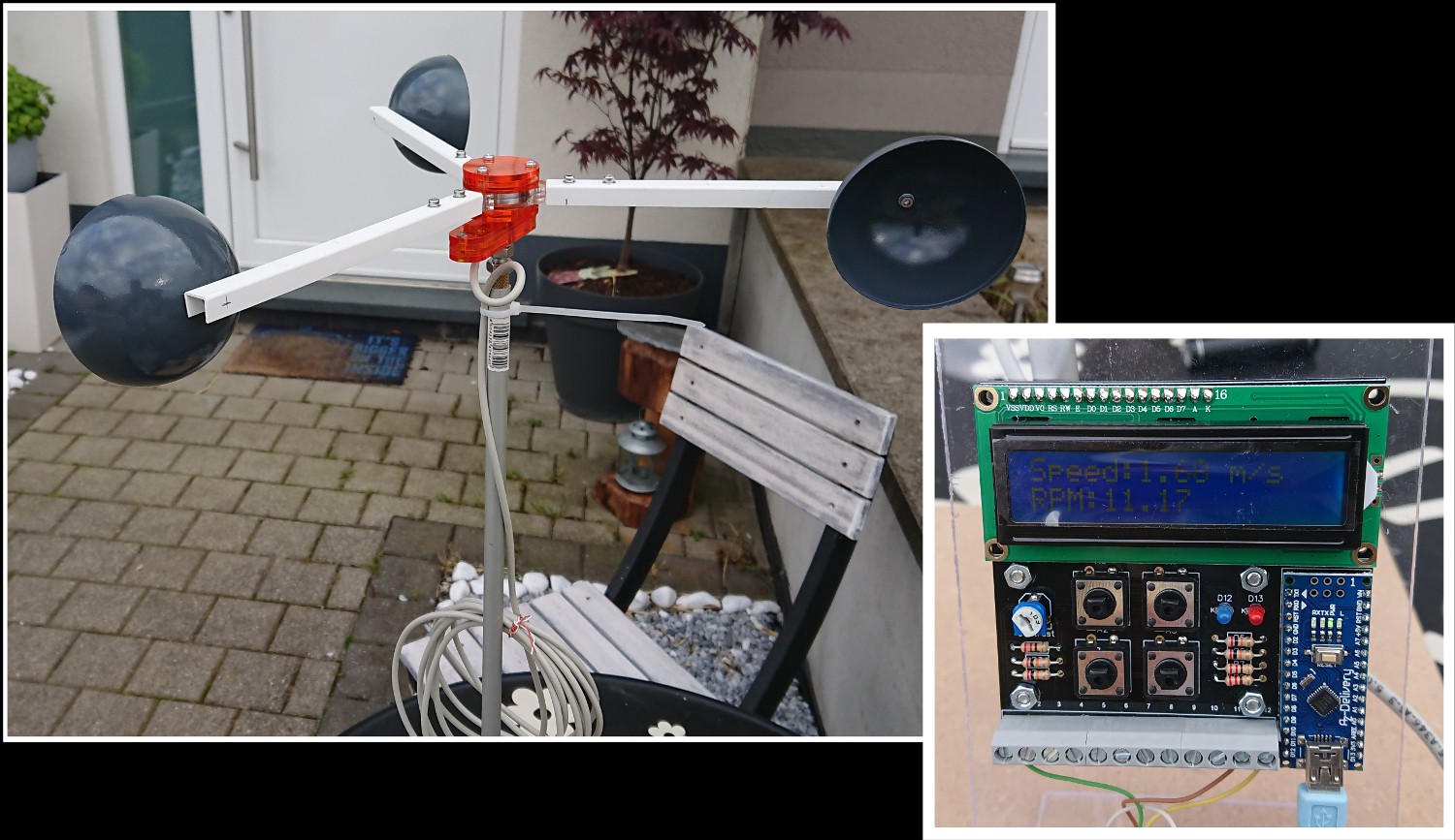
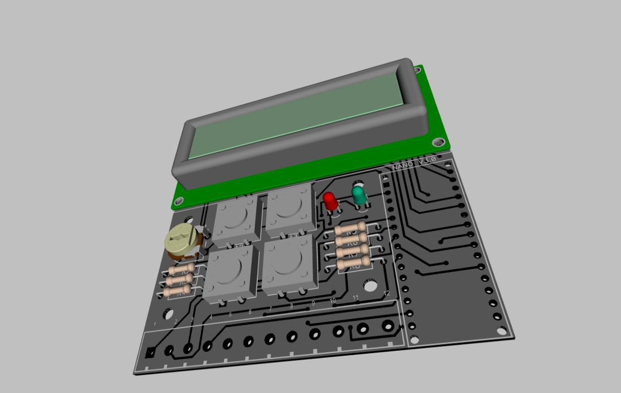
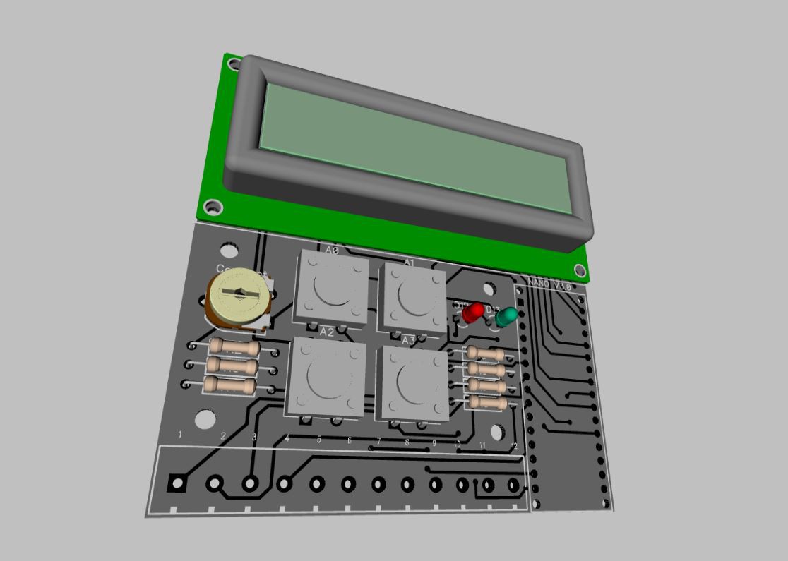
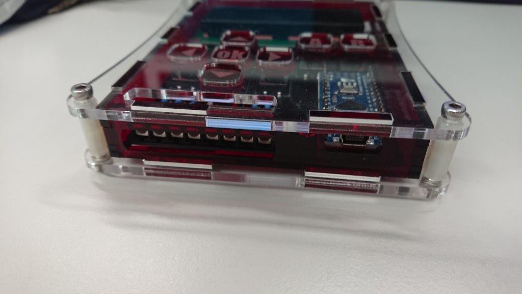
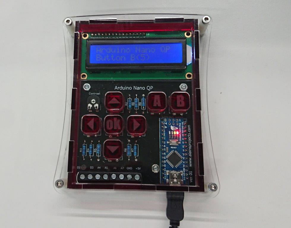
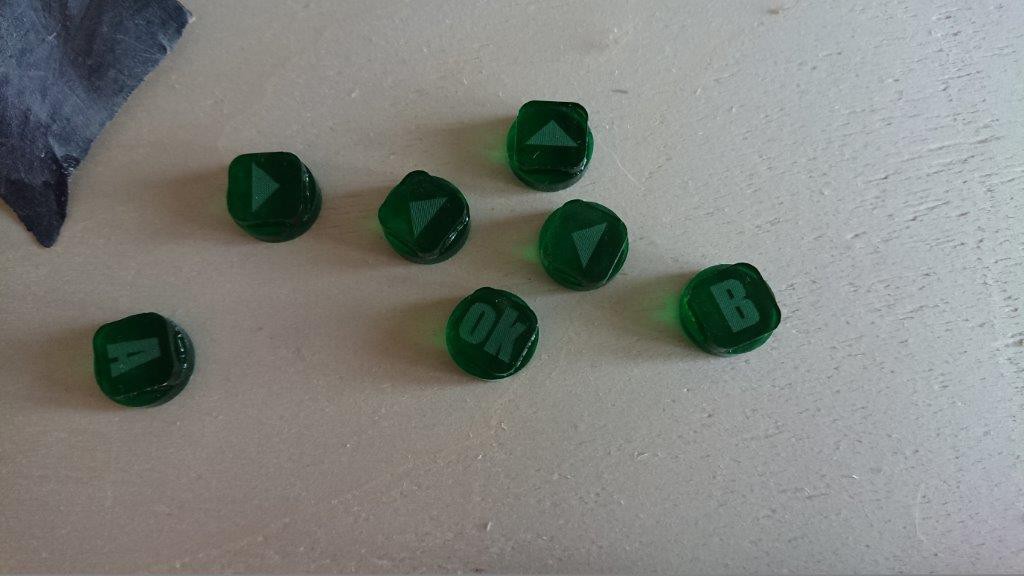
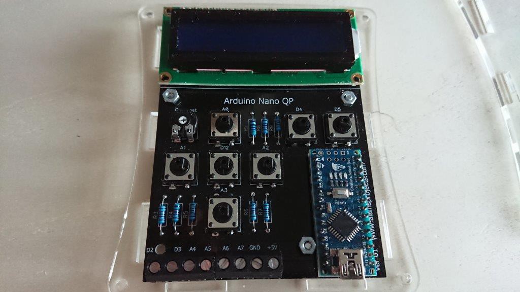
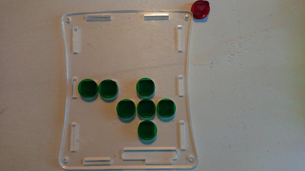
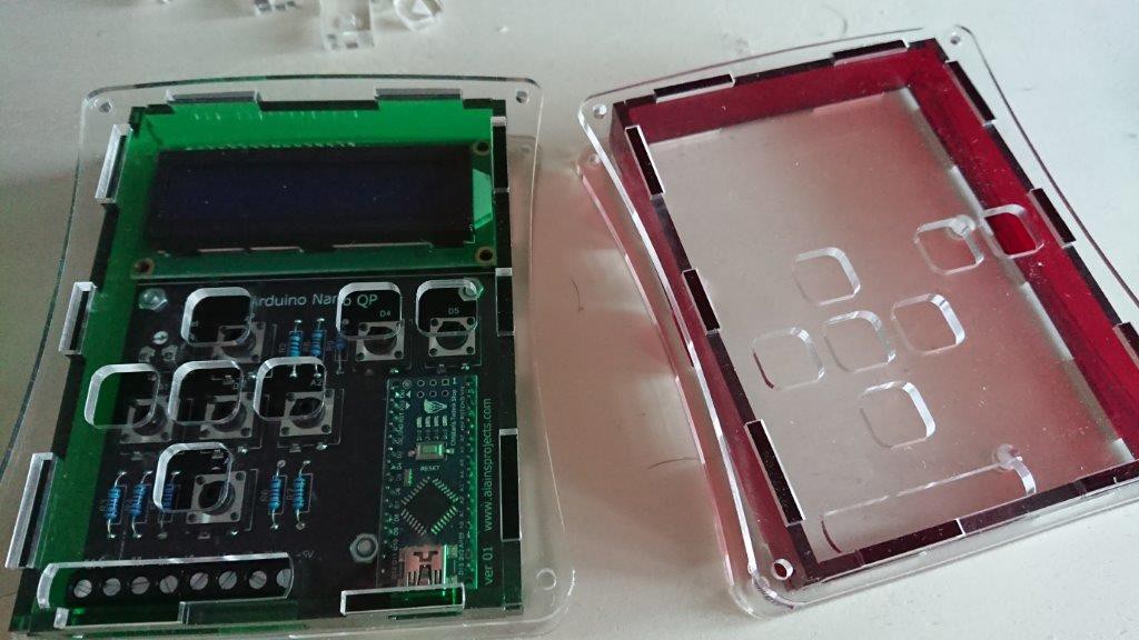
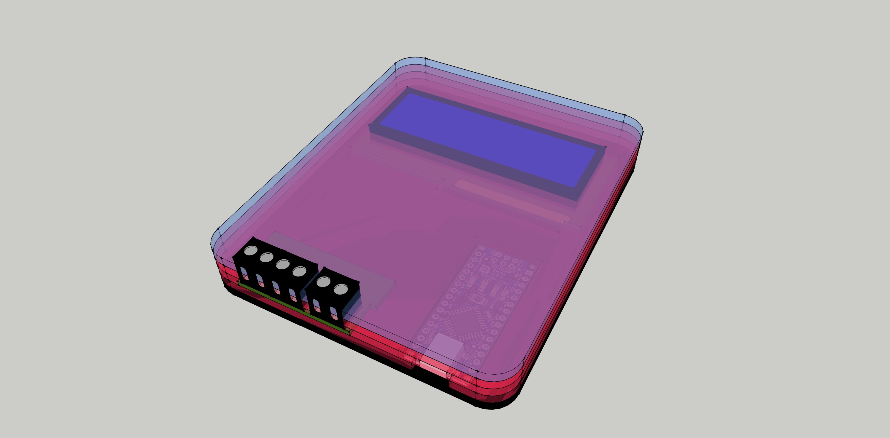
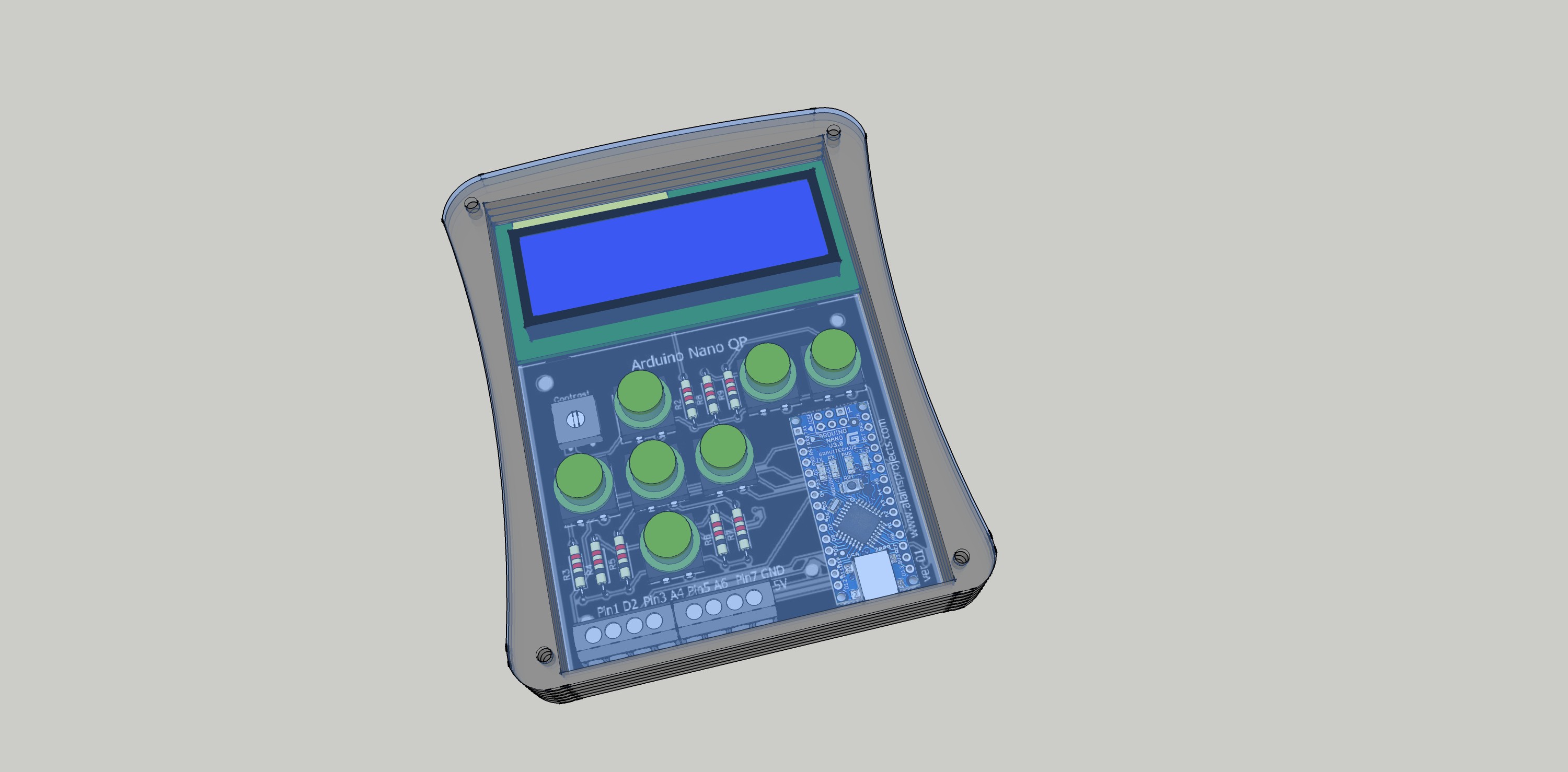
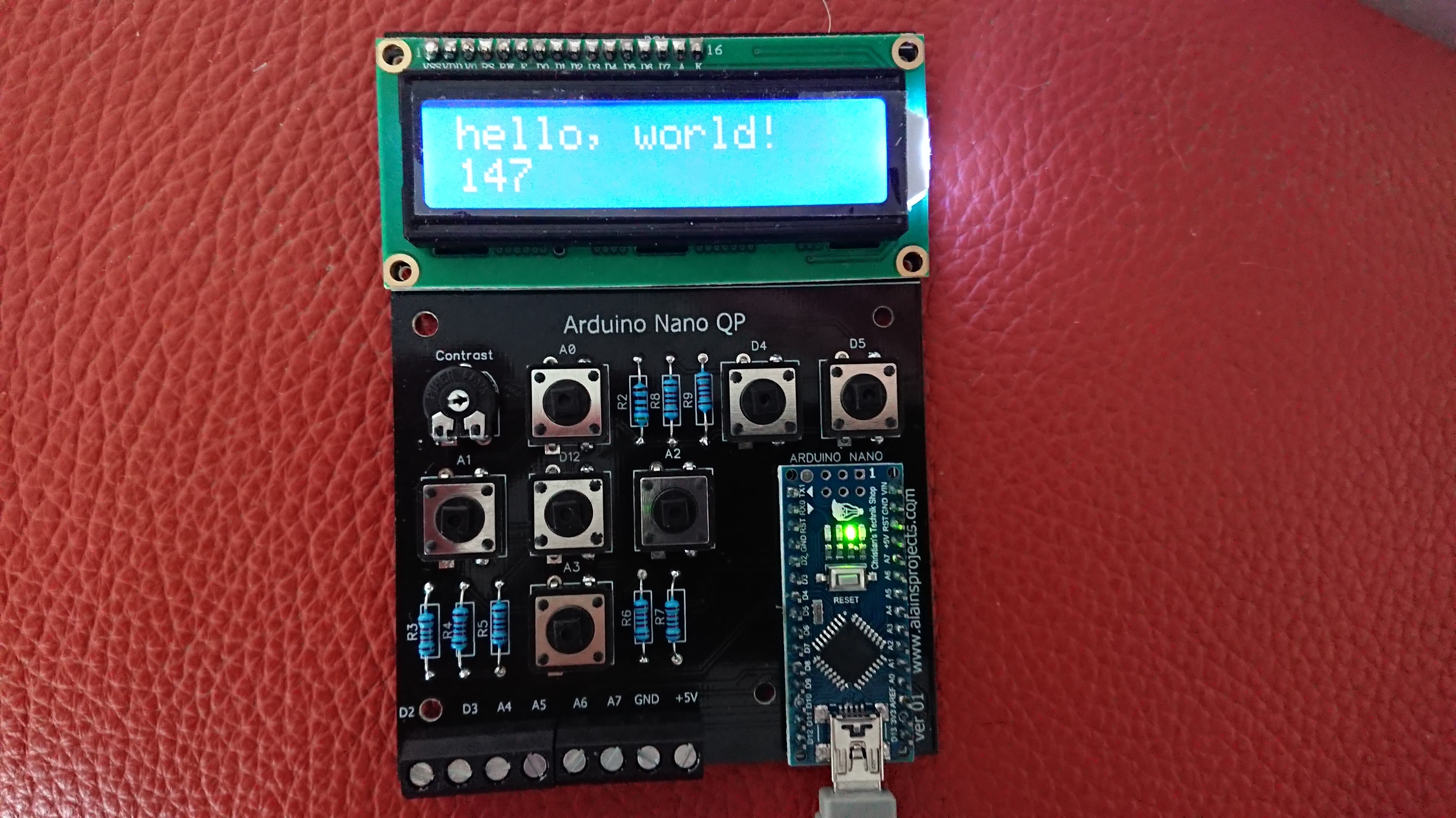
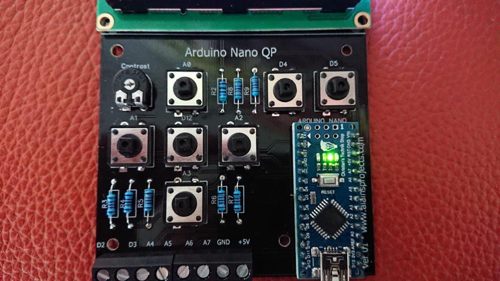
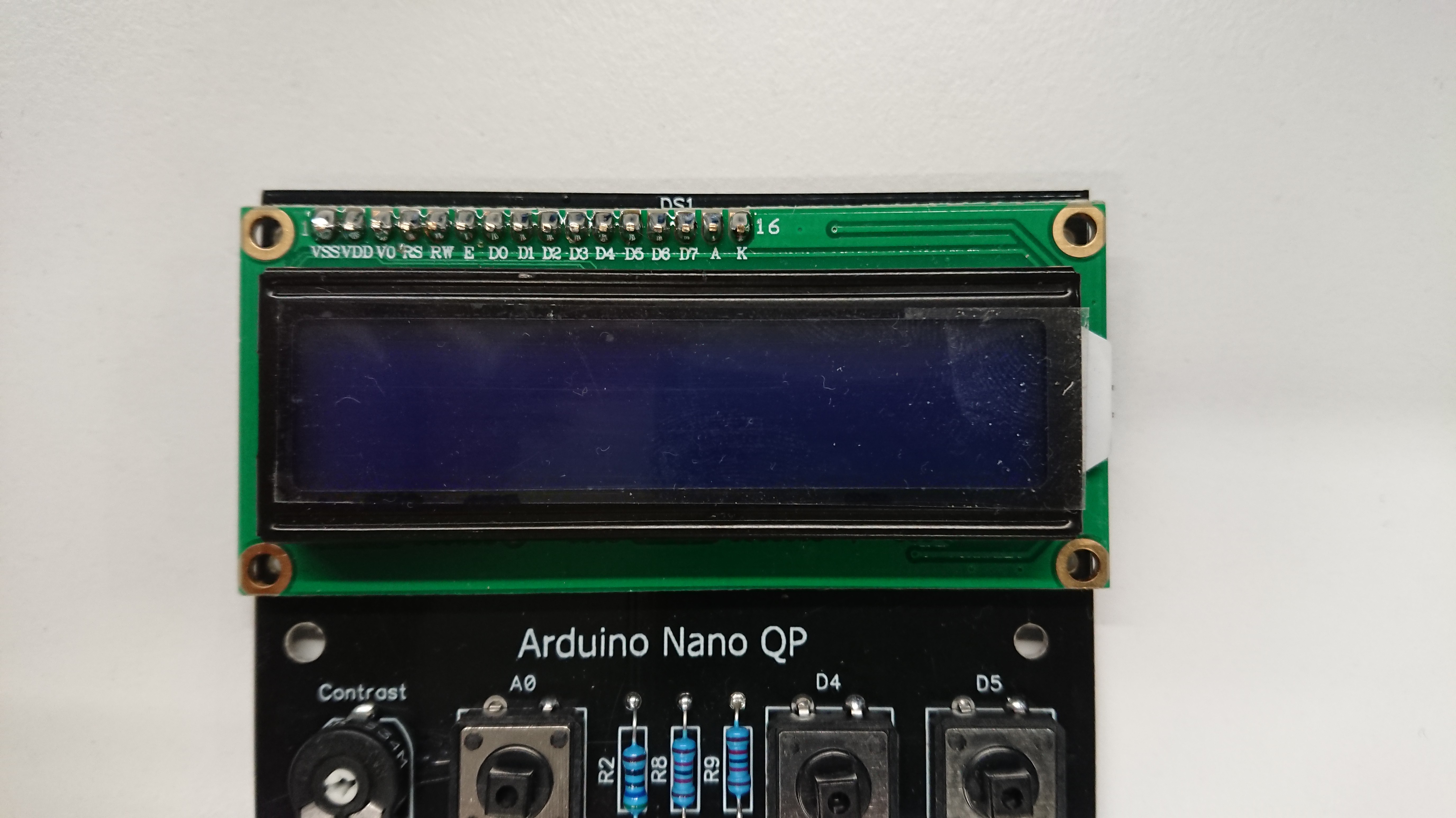
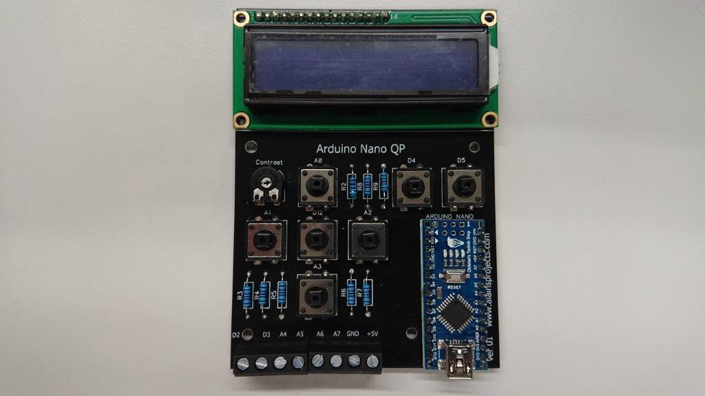
It's a ready to use box, which should be able to realize 85% of all the small ideas somebody can have. You have buttons, inputs, outputs, a display, serial (USB), a I2C interface and the onboard LED's. No more searching or soldering for a 10min project. Just take the Arduino Nano Q.P., upload your program and that's It. Use your Arduino where you want, in the lab, in the kitchen, in the bus ..... no more limits.

box-final.dxf

The DFX File for the enclosure

AutoCAD DXF - 172.12 kB - 07/04/2018 at 09:36

Download

  • 1 × Lcd Display 1602
  • 1 × Arduino Nano (or clone)
  • 7 × push button 12x12x7.3
  • 1 × Resistor 220R
  • 7 × Resistor 20k

View all 6 components

  • Ver 2.0 in action as Anemometer

    Alain Mauer06/01/2019 at 20:03 0 comments

  • Changed the design with community Input

    Alain Mauer07/17/2018 at 16:43 0 comments

    Working on a better version. A few people inspired me, to create a better version.

    Here is the next PCB. Smaller, less buttons, more I/O, two LED's and Serial

  • The final Touch

    Alain Mauer07/06/2018 at 08:23 0 comments

    The screws and the spacers are finally here.

    So let's mount all together and start with the first project.

  • Lasercutting and Assembling

    Alain Mauer07/03/2018 at 11:41 0 comments

    And now to the workshop, powering on the 30W lasercutter. I use 3mm Arcylic.

    Screwing the PCB on the Back Part with 3xM3 screws

    Now the buttons in the frontpart and insert the frame parts

    Now insert the back part on it. Just the 4 mounting screws are missing, they should reach me by friday.

    And I can do it in more colors :)

  • The Enclosure

    Alain Mauer07/03/2018 at 11:28 0 comments

    It is not necessary, but with an enclosure it's cooler. Now the Arduino Nano QP, can even be used ass a finished project, or as part of a bigger project.

    Designing an enclosure.

    And here is the design I took:

    "Picture is comming"

  • First Running Test

    Alain Mauer07/03/2018 at 11:22 0 comments

    I wrote a small Software, to test the Display and all the I/O's of the board,

    Seems to work :)

    The test software can be found on Github

  • Soldering

    Alain Mauer07/03/2018 at 11:18 0 comments

    Now I solderd all the parts to the PCB

  • The PCB

    Alain Mauer07/03/2018 at 11:13 0 comments

    All starts with a circuit diagram. It's not very complicated, everything has just to be connected to the Arduino

    Then place the parts and autoroute all

    Even in 3D

    Now upload the files to a pcb manufactor and wait for the result

View all 8 project logs

  • 1
    ​Glue the Buttons

    The buttons are made of two parts and they have to be glued together, which is a sticky job for the fingers and the glue makes stains on the acrylic.

    So I build a template. 2 Parts are made out of acrylic and 2 out of wood.

    4 Srews keep all in place. I placed the top button part in his tempate. The wood part keeps all in place.

    Now the round parts with the template on the top. I put a little bit of superglue on the round parts.

    Then the second wood part on the sandwitch construction and with the nuts, all is pressed together for 30min

    And the Buttons are ready, nicely aligned and no stains.

    And the Buttons are ready, nicely aligned and no stains.

View all instructions

Enjoy this project?

Share

Discussions

programacionisrael wrote 08/09/2019 at 12:36 point

how contact you dear friend?

  Are you sure? yes | no

David Cruickshank wrote 07/20/2018 at 00:27 point

Hi there. Great design and elegant layout! I've built one of my own based off yours, but since I had several Unos sitting on the shelf I used one of those and a shield. I've done the solder connections to the shield so I can reuse the Uno if I need to.

Here's a link to mine. https://hackaday.io/project/159867-quick-n-dirty-arduino-project

  Are you sure? yes | no

Alain Mauer wrote 07/20/2018 at 08:11 point

The result is the same. It works :)

  Are you sure? yes | no

agp.cooper wrote 07/07/2018 at 08:18 point

I have had second thoughts about suggesting that you swap A4-A7 with A0-A3.

Although you can use analog input (only) for switches (A6-7), the code has to test the analog value returned so it is a bit more complicated (I forgot about this).

Also A4 and A5 are the I2C pins and they are very handy for hooking up to devices like a real-time clock or a port expansion.

Perhaps reducing the number of switches. For my "box" I used a single rotary/push button switch. Unfortunately the interrupt service routine interferred with the I2C communications with a EEPROM so I had to drop the rotary encoder. My work around was to use diffferent press durations (tap, push, short hold and long hold) for menu navigate, select/enter, and  data download and reset. Not suggesting you need to be so extreme as this but you don't really need 5/7 buttons for a menu system (unless it is a game console?).

Regards AlanX

  Are you sure? yes | no

Alain Mauer wrote 07/16/2018 at 12:40 point

Hi, I redesigned my PCB, and you are right, I optimized it a little bit. 
Now it has 2 AD or I2c, Tx and Rx, 4 digital I/O(2 Int and 2PWM) and GND and +5V.
I will put the new PCB online here on Hackaday in a few days. 

The 7 Buttons were more, because of the look. In fact four should be enough.

Thanks for your input.

  Are you sure? yes | no

agp.cooper wrote 07/16/2018 at 16:25 point

Yeah, that is pretty close to what I would do.

---

When picking the PWM pins, check that it matches the timer you like to use for Interrupt Service Routines (ISRs). I tend to use Timer2 (8 bit) which outputs on D3 and D11. Timer1 (16 bit) has a nice library (TimerOne) and outputs of D9 and D10.

Generally you cannot use Timer0 (D5 and D6) for an ISR as it is used for delay(), millis() and micros(). Not true (of course), if you know what you are doing.
--

With the LCD menu code don't forget to check out some of the work by other people. Some of the code (and libraries) are quite clever and easy to used.

Regard AlanX

  Are you sure? yes | no

bobricius wrote 07/04/2018 at 22:56 point

nice idea for rapid prototyping, perfect enclosure ;)

  Are you sure? yes | no

Alain Mauer wrote 07/05/2018 at 06:01 point

That was the plan. I really want to use more often an Arduino, but it's boring, to connect the display or buttons to it and then  search one hour, why something does not work. The enclosure just adds the finaltouch

  Are you sure? yes | no

agp.cooper wrote 07/04/2018 at 12:13 point

Nice, well done.

One small improvement would be to swap A0-A3 with A4 to A7, as A6 and A7 are input only pins.

You may want to put a 220R to 1k resistor inline of the input/outputs. Two reasons, to limit possible high currents entering the Nano (such accidentally touching a baterry ternimal - done that before!) and high currents from the Nano (up to 40 mA!) damaging a device (such as a bus conflict on a memory chip - done that before too!).

  Are you sure? yes | no

Alain Mauer wrote 07/04/2018 at 12:19 point

Thanks for your input. I'll re-think my design for V3.0 , because I have already ordered the PCB for V2.0 :)

The pin swap and the input protection are really a good idea. Thank You. Greetings from Luxemburg

  Are you sure? yes | no

Similar Projects

Does this project spark your interest?

Become a member to follow this project and never miss any updates