 Chris Graham
Licenses
0%
0%
Multiwind
A modular system for multimodal hands-free music control, wind instrument development and general human computer interaction.
Become a Hackaday.io member
Already have an account? Log in.
Just one more thing
To make the experience fit your profile, pick a username and tell us what interests you.
Pick an awesome username
hackaday.io/
Your profile's URL: hackaday.io/username. Max 25 alphanumeric characters.
Pick a few interests
Projects that share your interests
People that share your interests
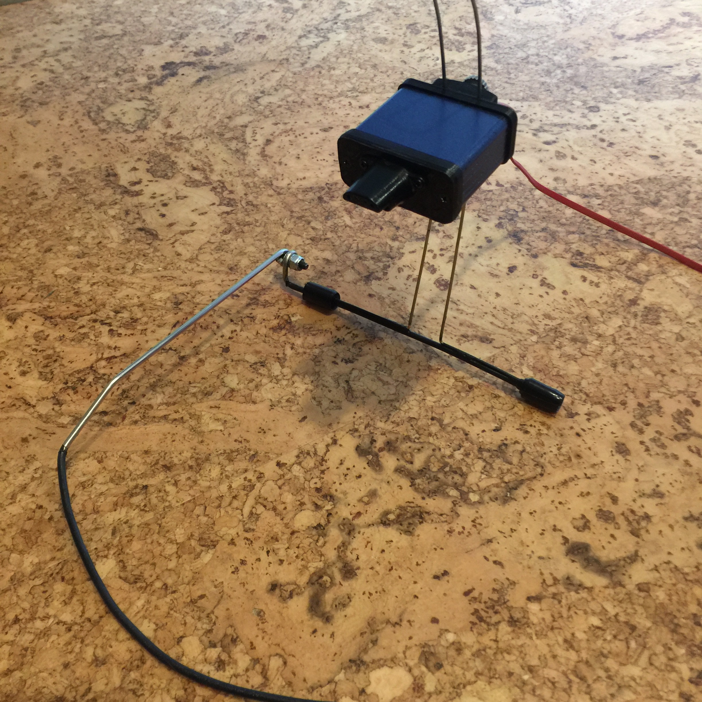
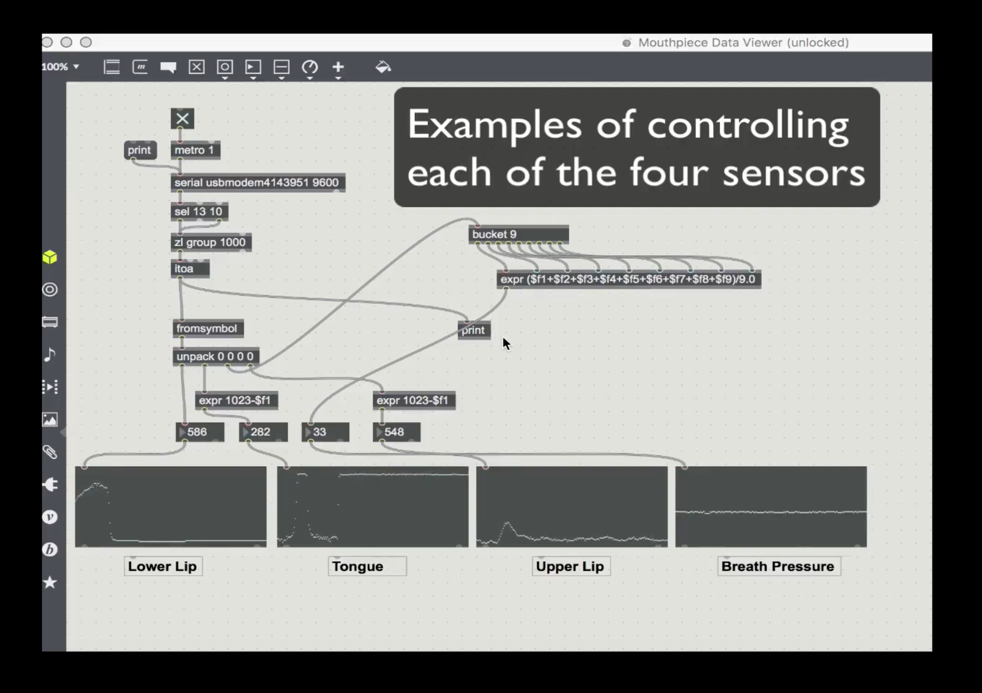
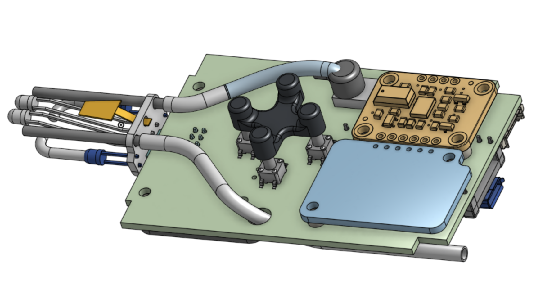
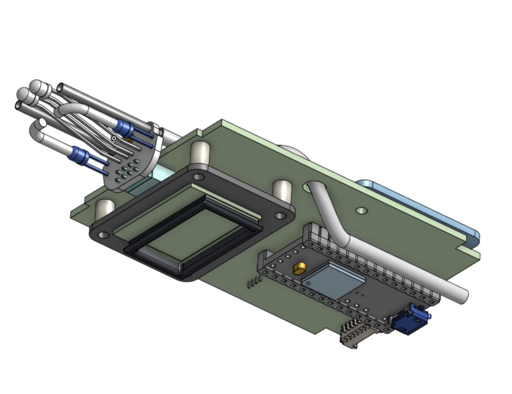
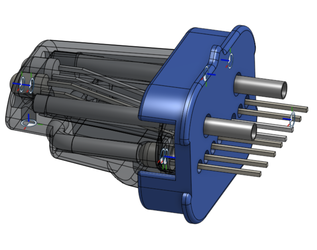
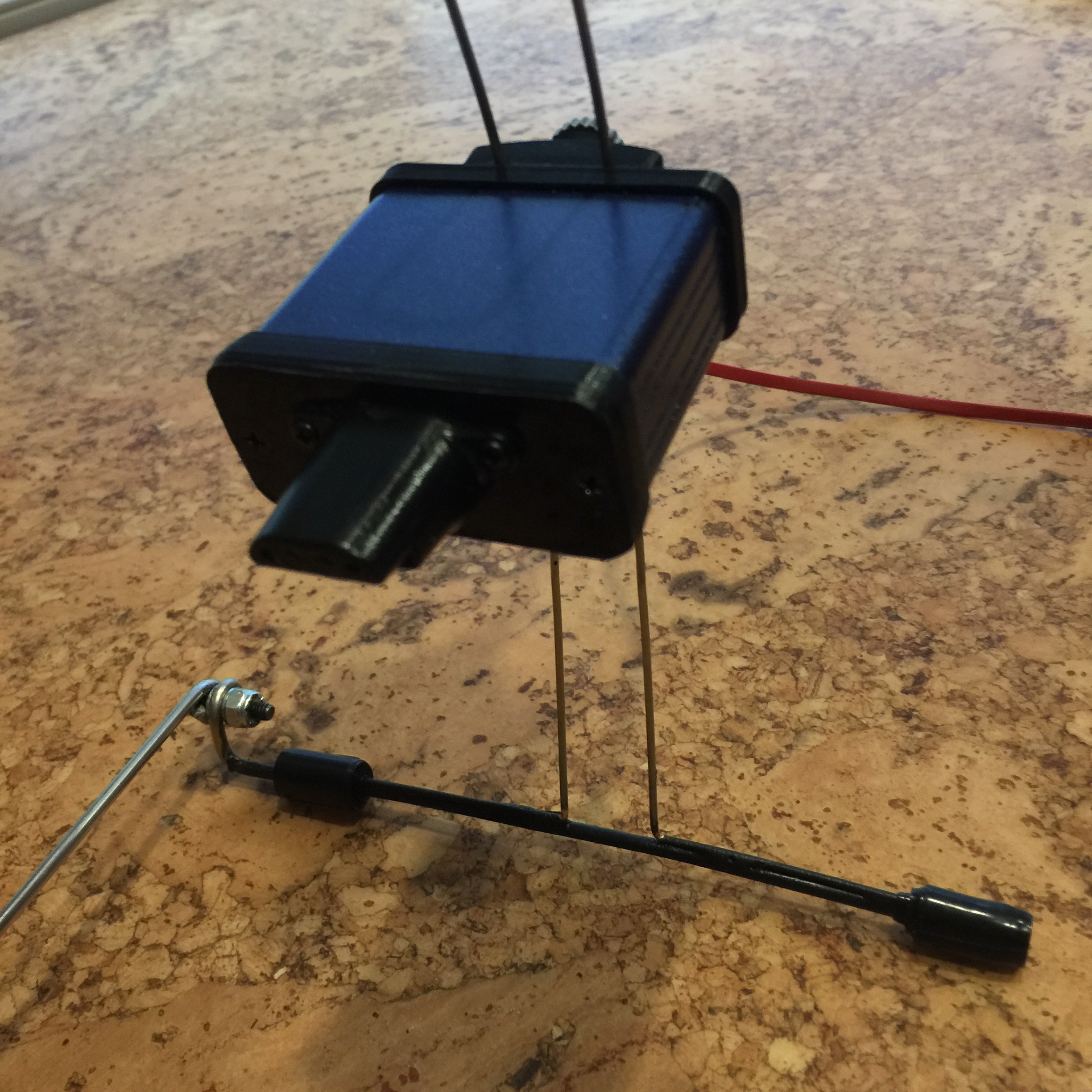 This mouthpiece has sensors for:
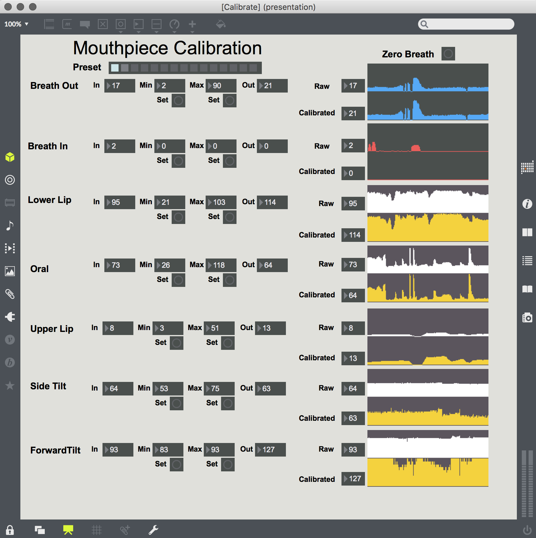
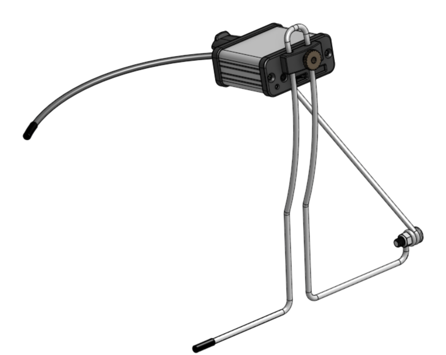
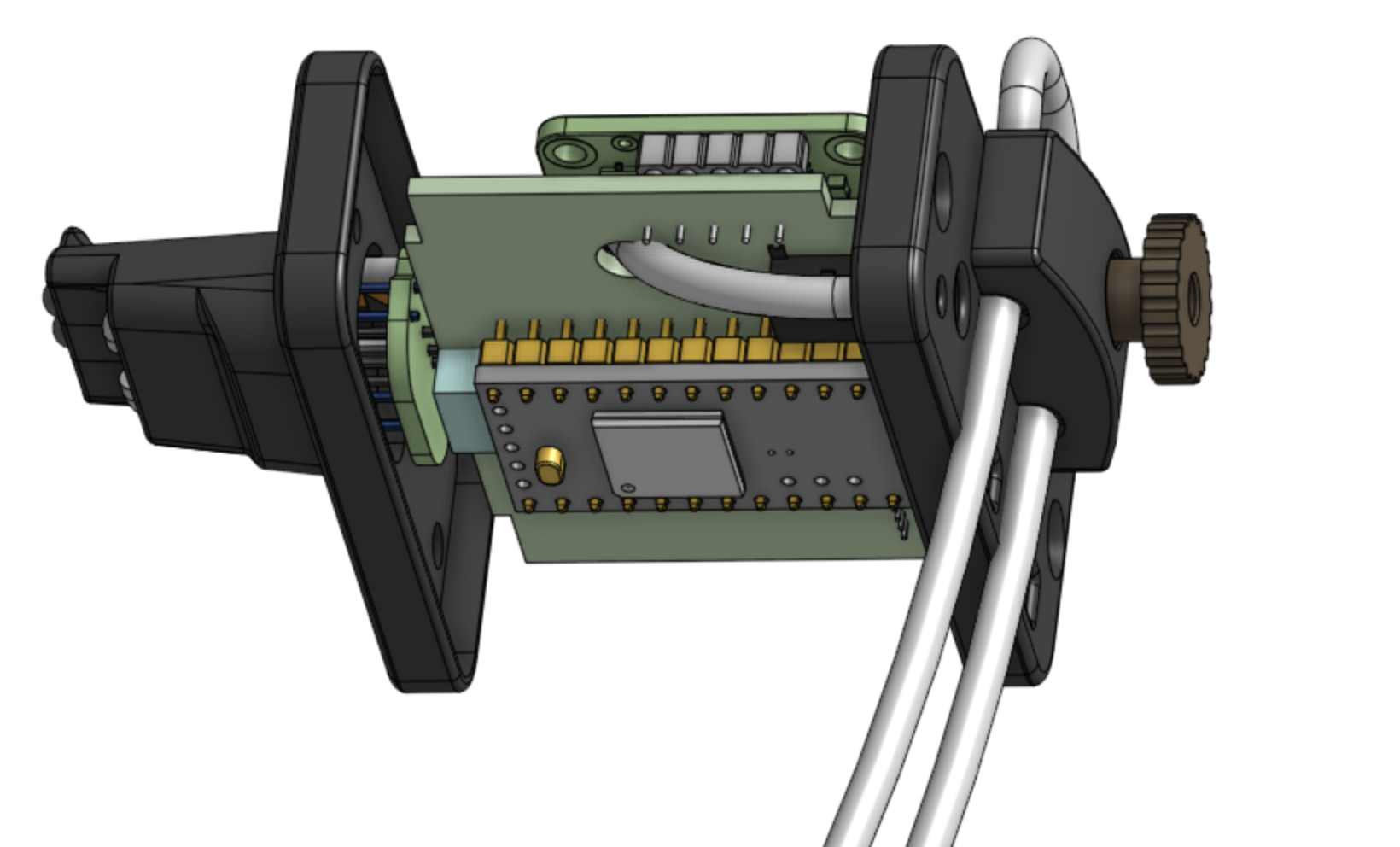
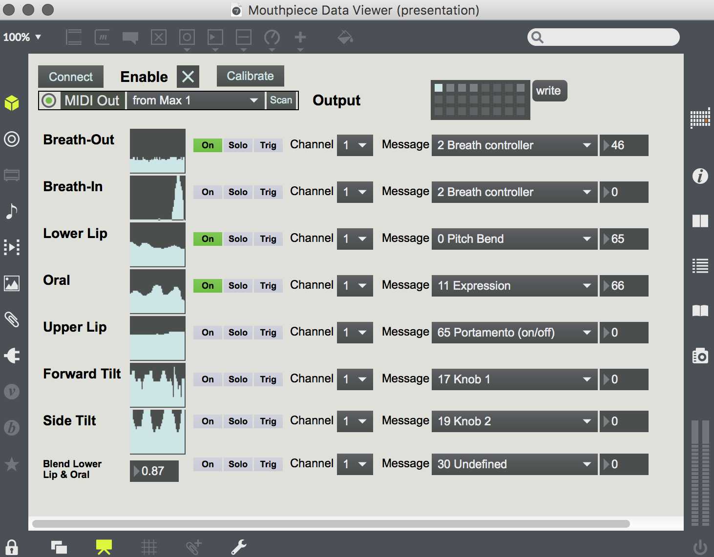
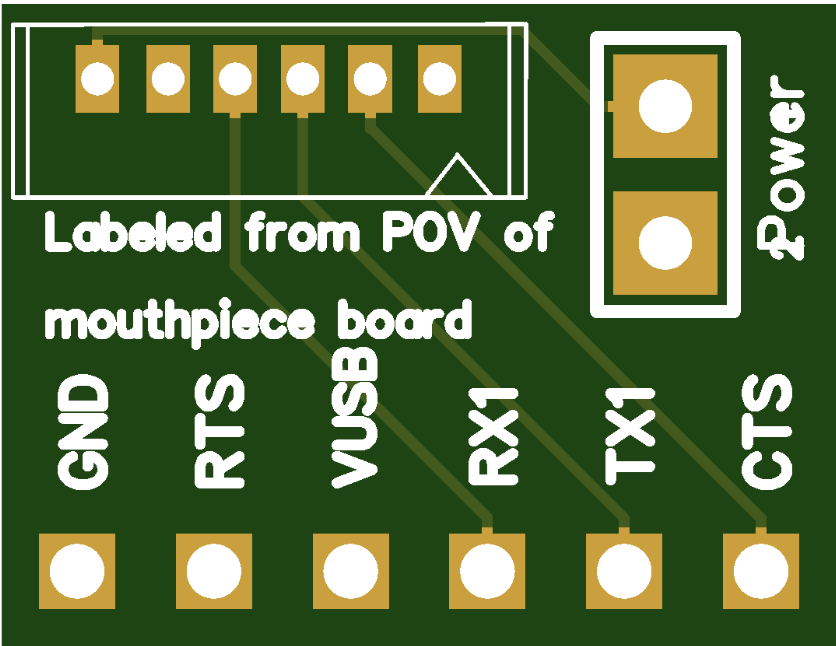
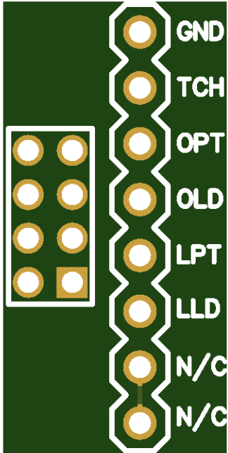
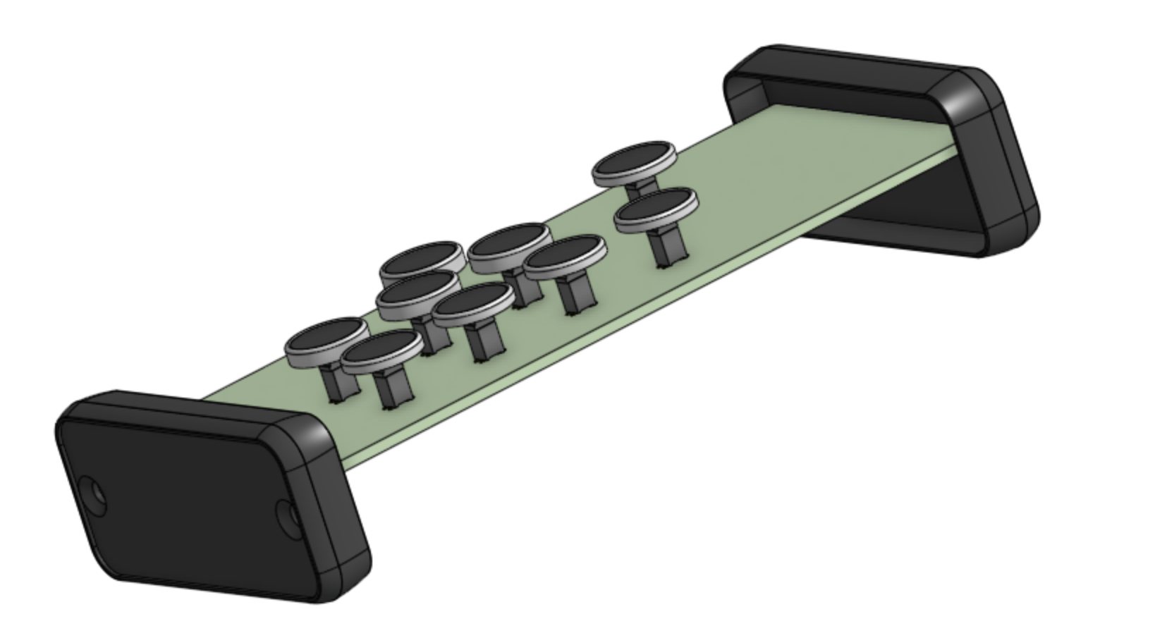
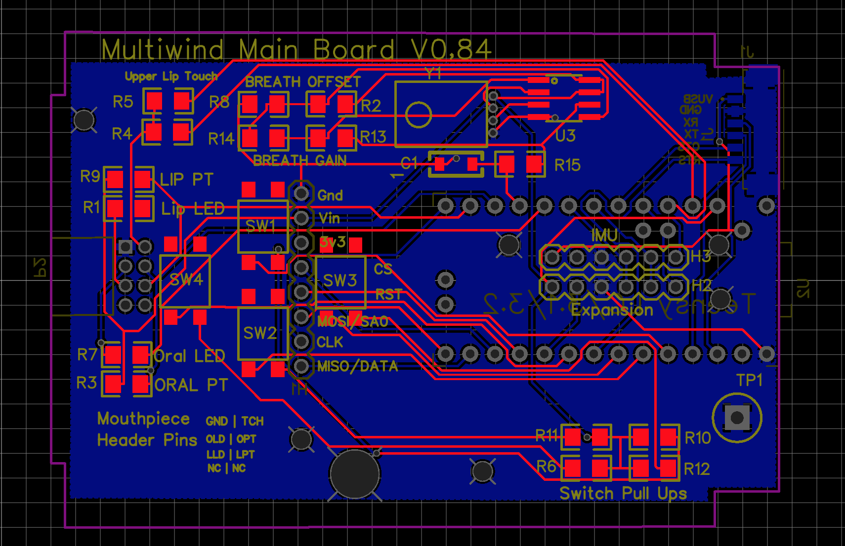
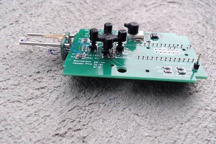
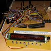
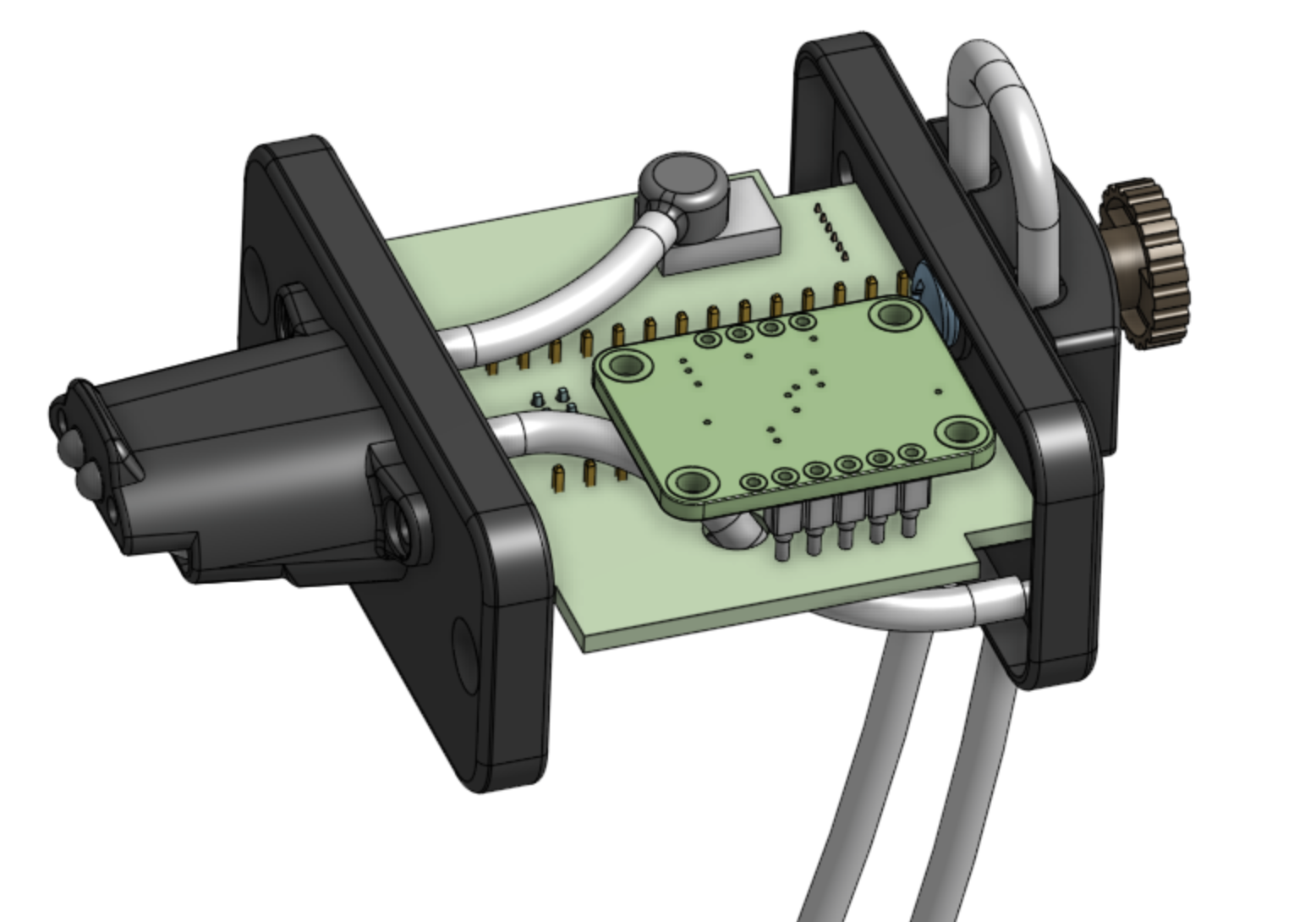 The mouthpiece still includes a header to mount any of the three types of Adafruit IMUs. I also also added a MIDI out. The connector is a 2.5 mm TRS jack compatible with various 2.5mm to standard MID adapter cables that are available. You can see the MIDI connector in the opened image of the bottom of the PCB. It's the black component behind the tube on the lower right.
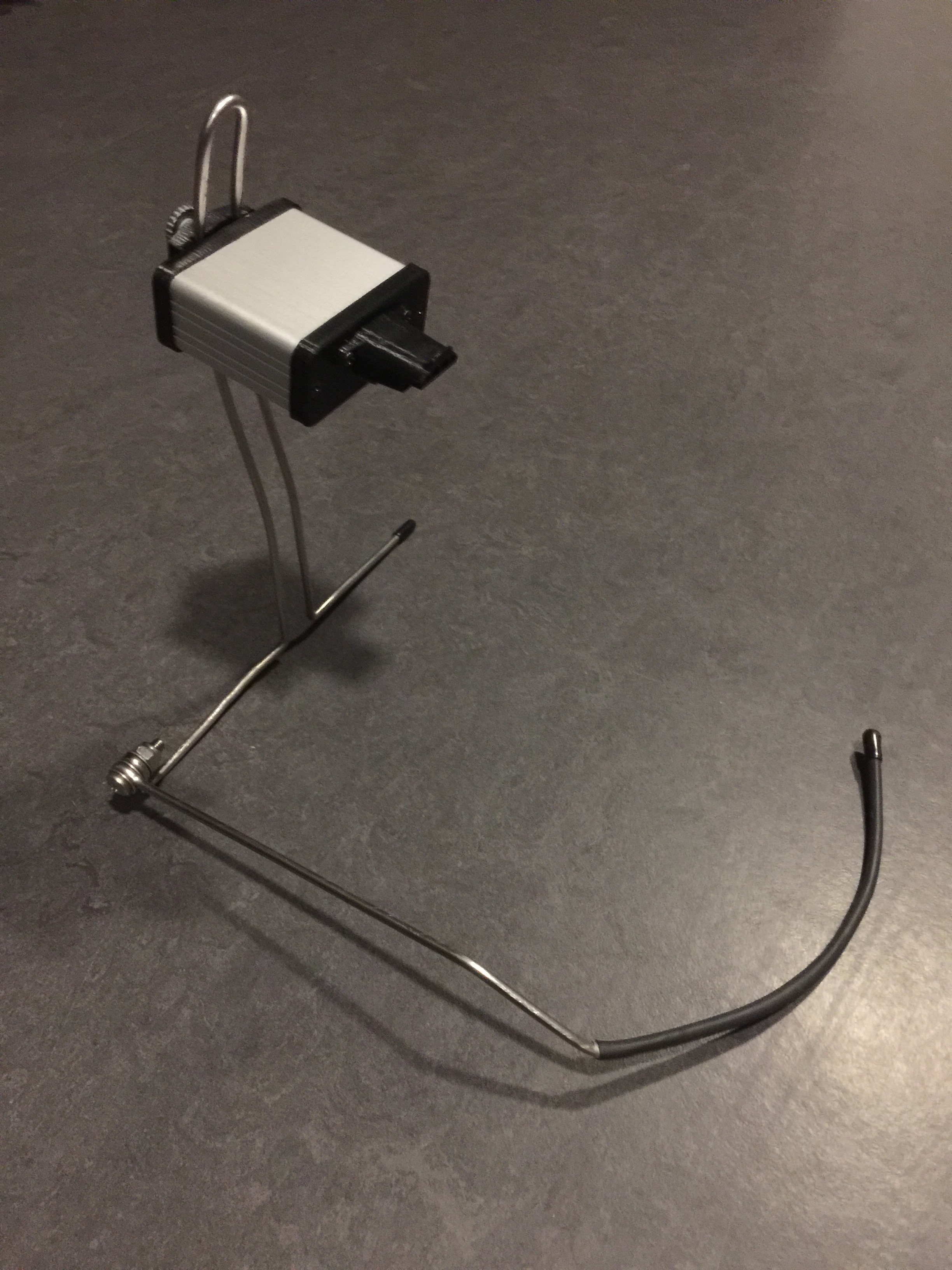
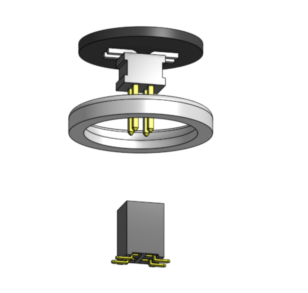

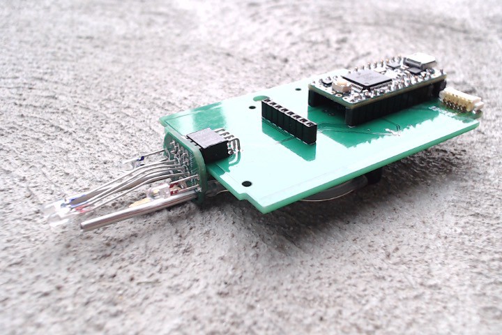
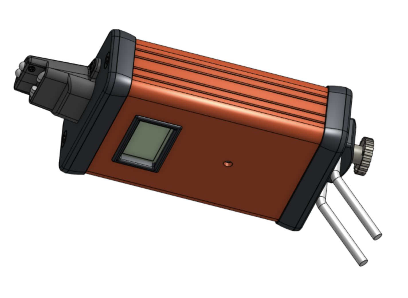
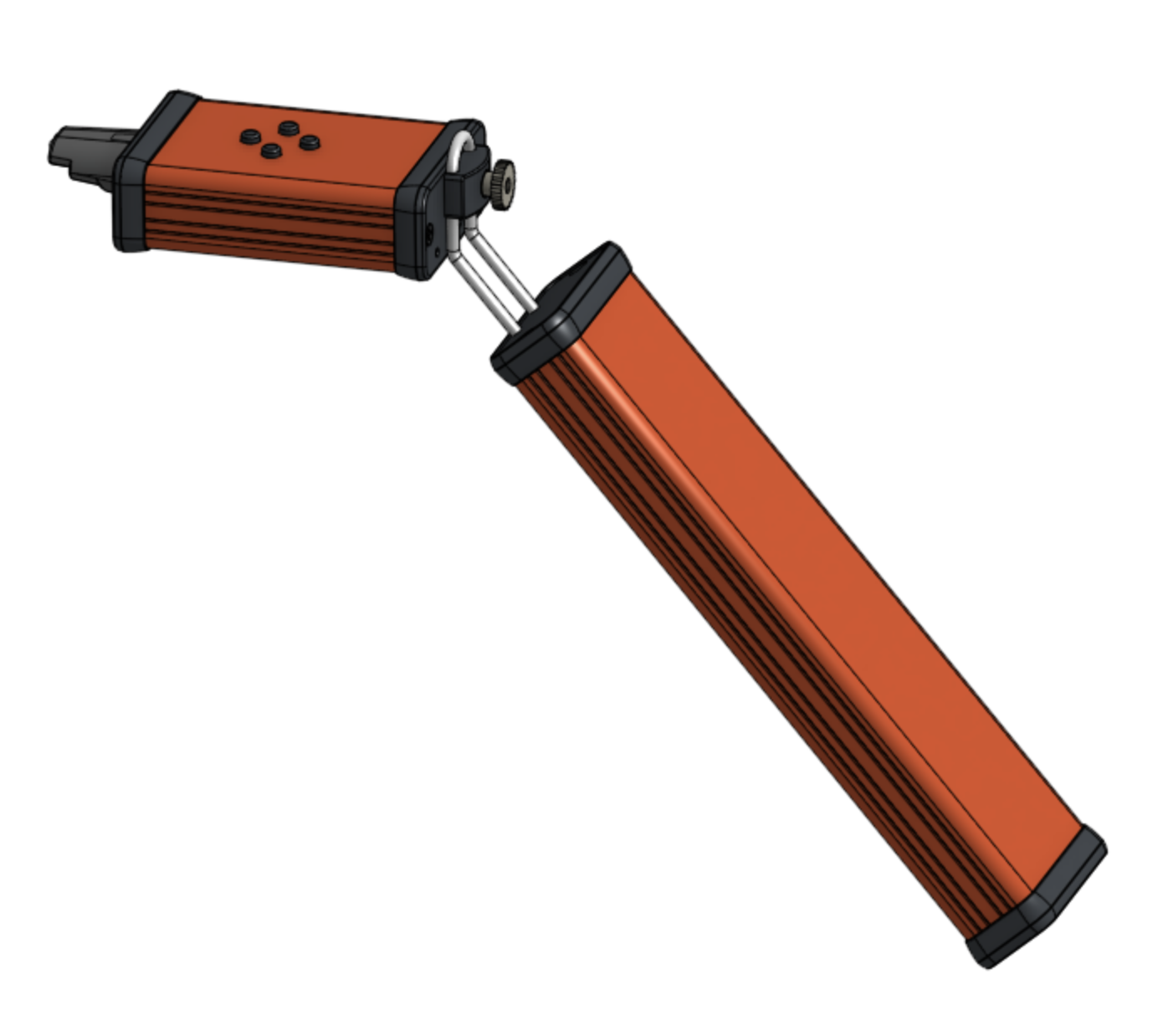
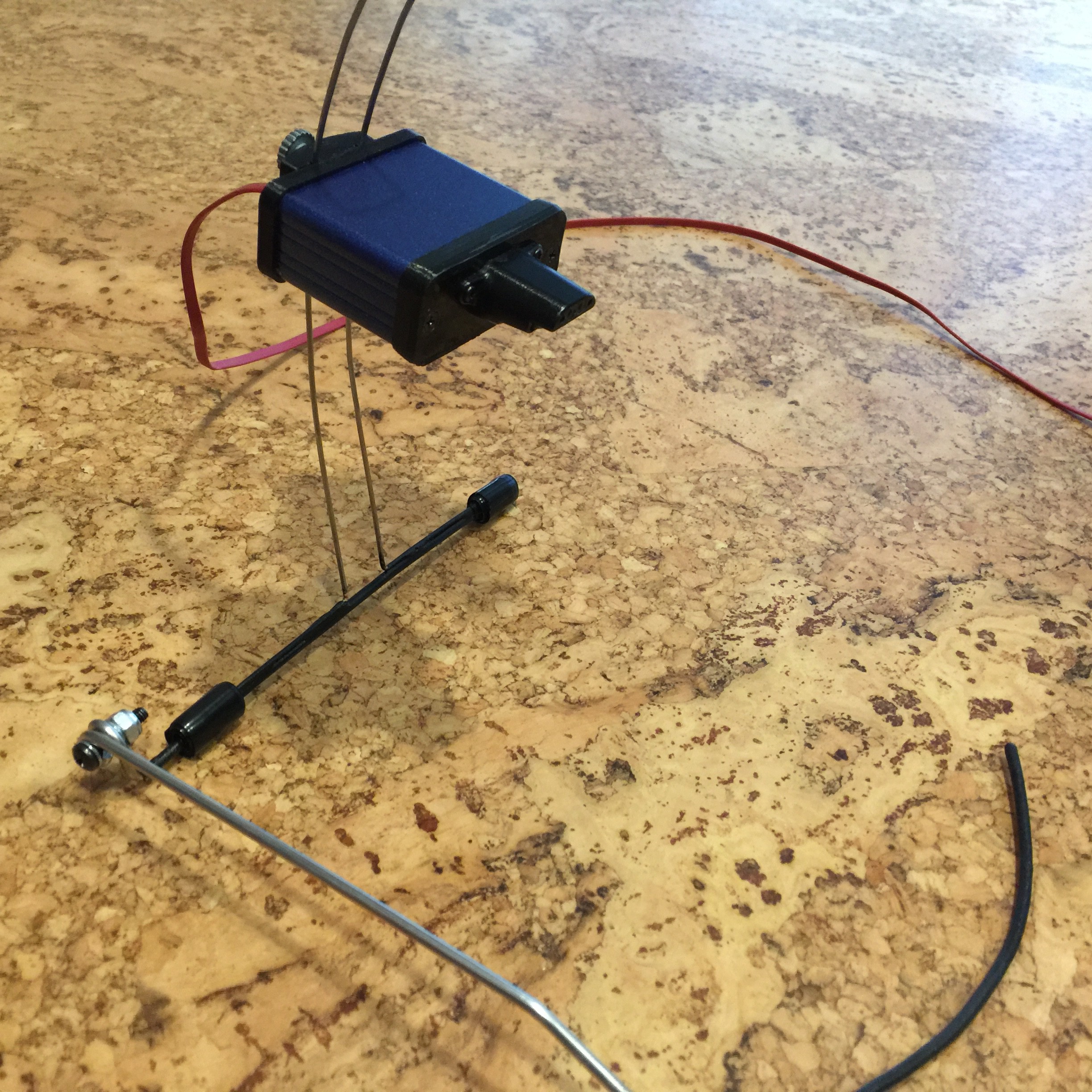
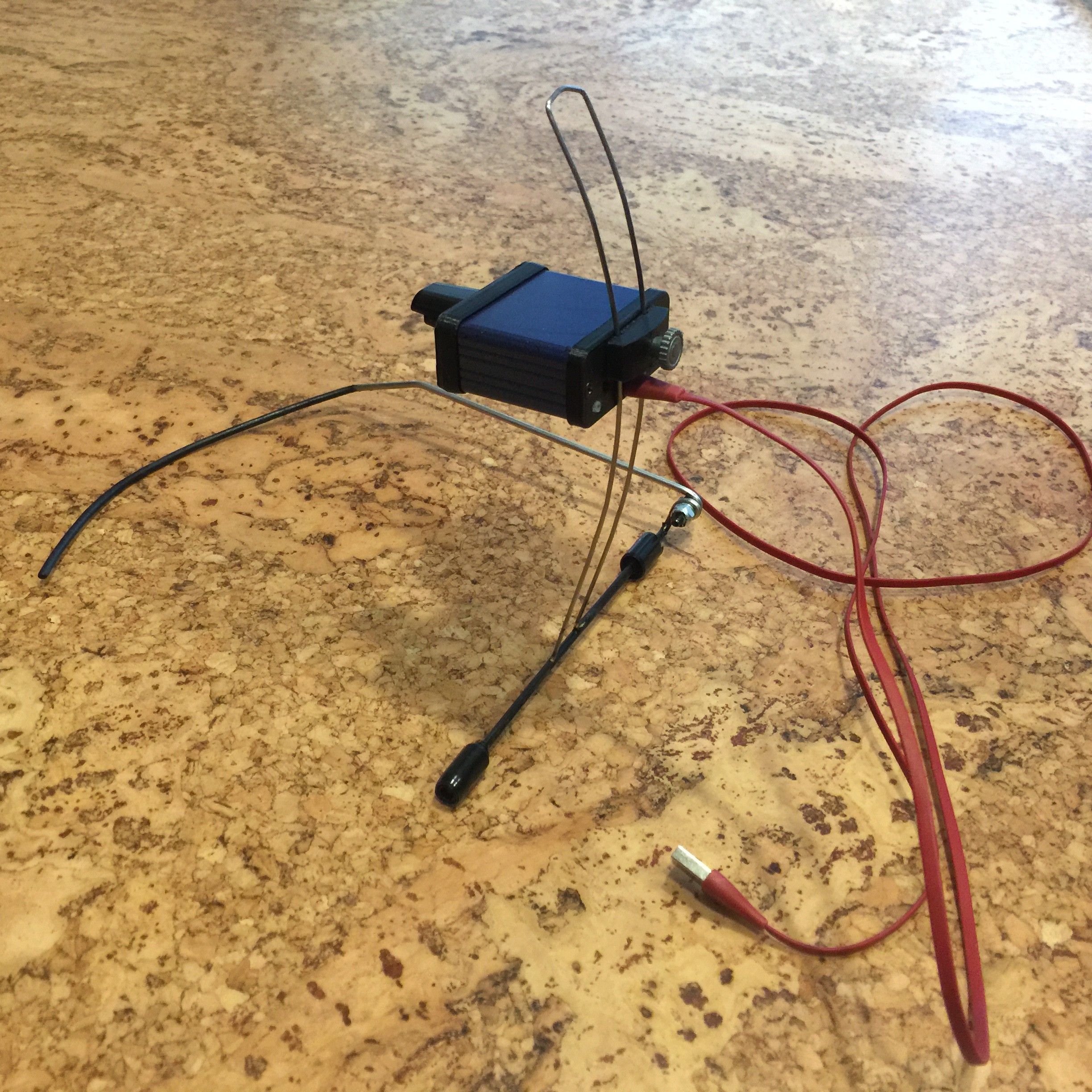
 Forming the leads is tricky to do accurately enough so I designed and 3D printed die for forming the leads:
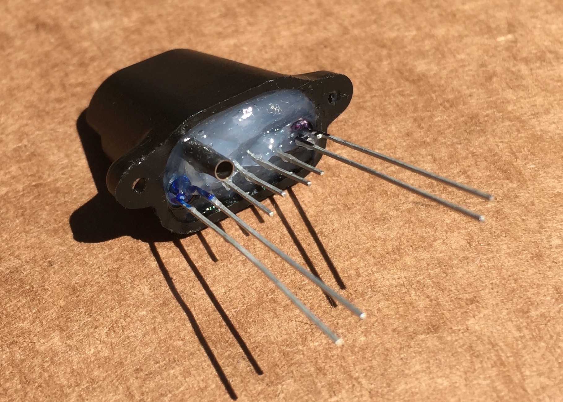
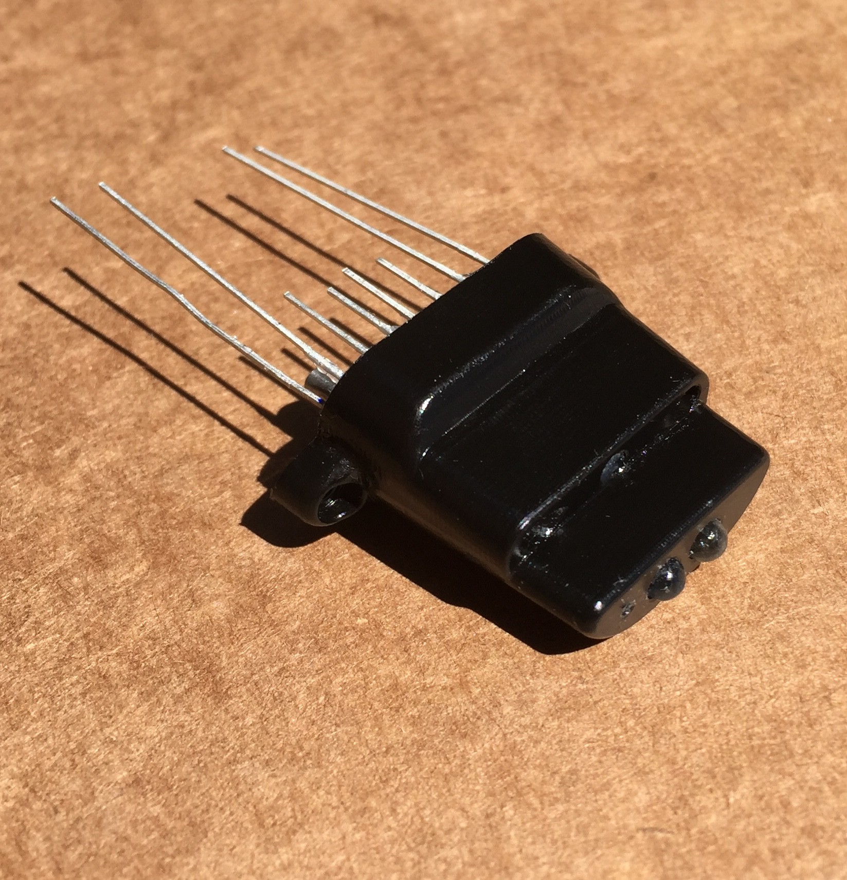
 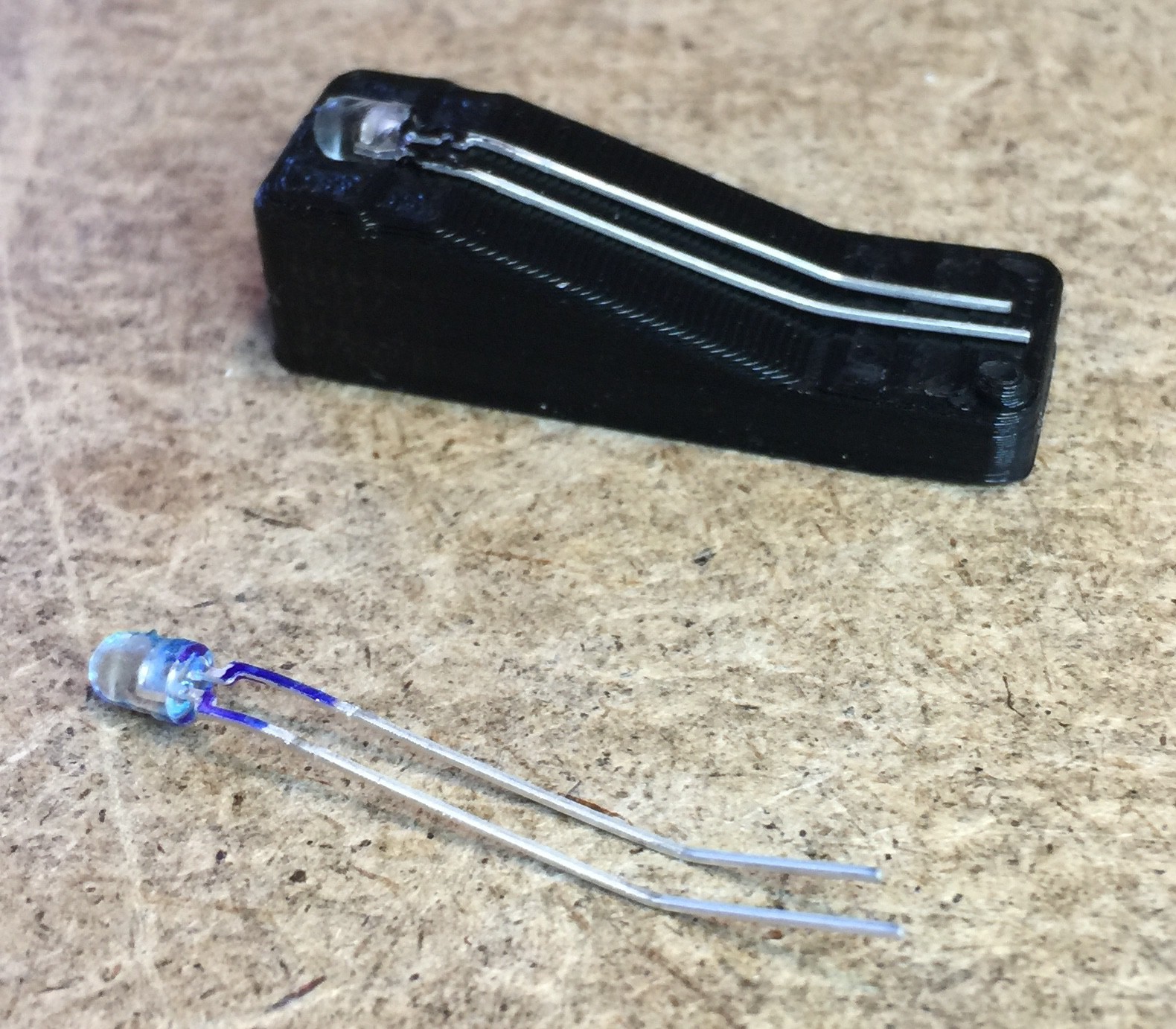 To use: Place the head of the part in the cavity on the left upper surface of the die, hold the head down firmly, press the leads into the forming surfaces and you have leads with the perfect shape. You can see I made blue and black markings on the parts to distinguish LEDs from Phototransistors as they look exactly the same.
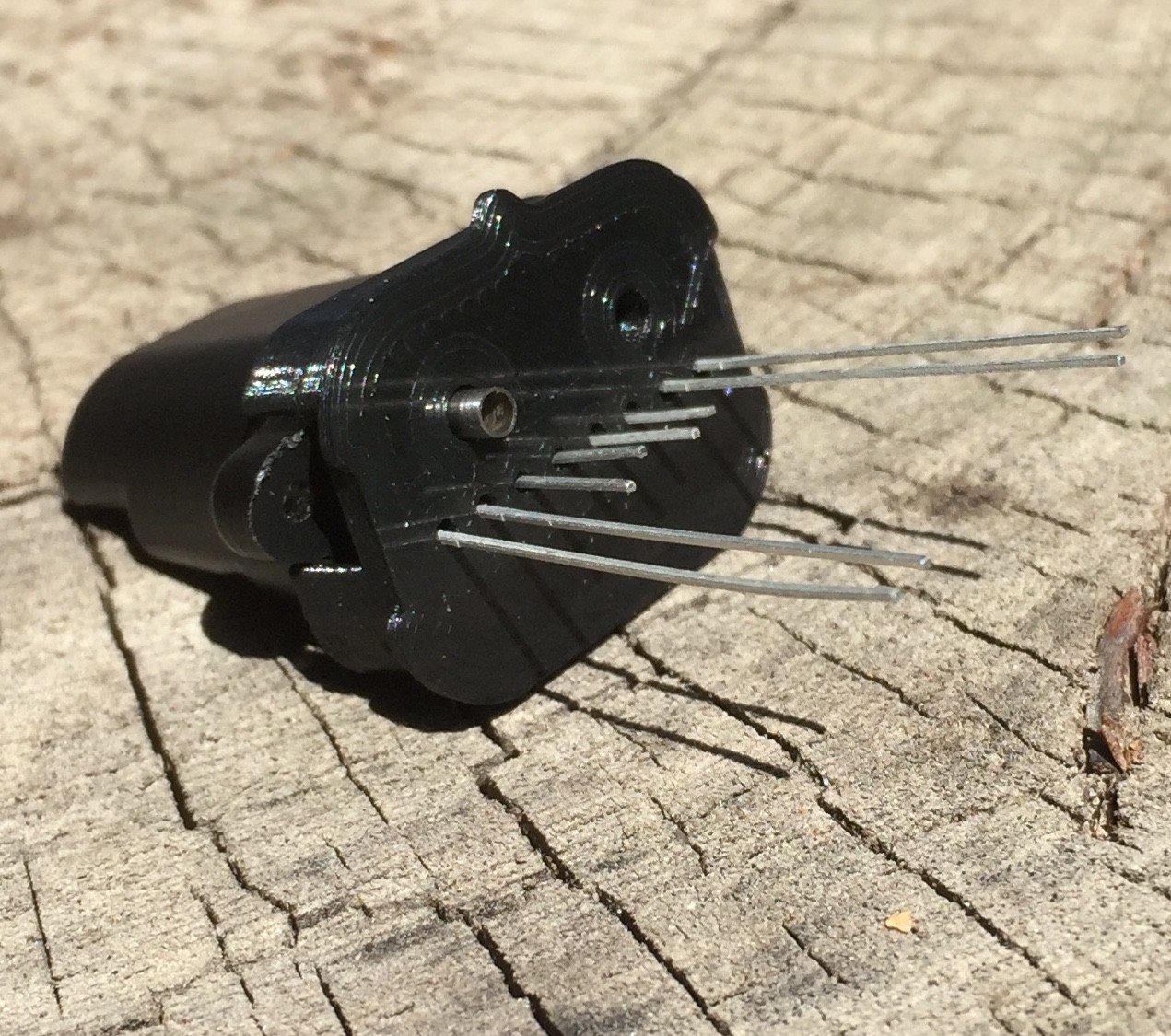 The jig can be removed when the potting compound hardens. For the future I'm going to make a version of the jig with a hole to inject the potting compound through. Also I ordered a tube of this epoxy from Atom Adhesives:
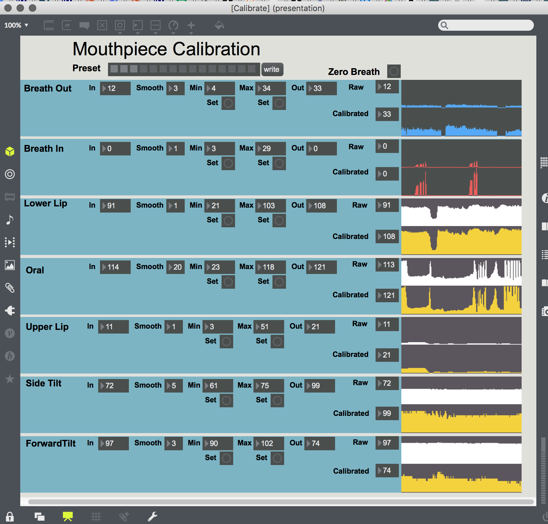
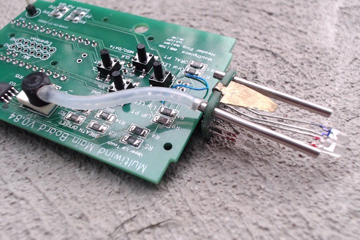
 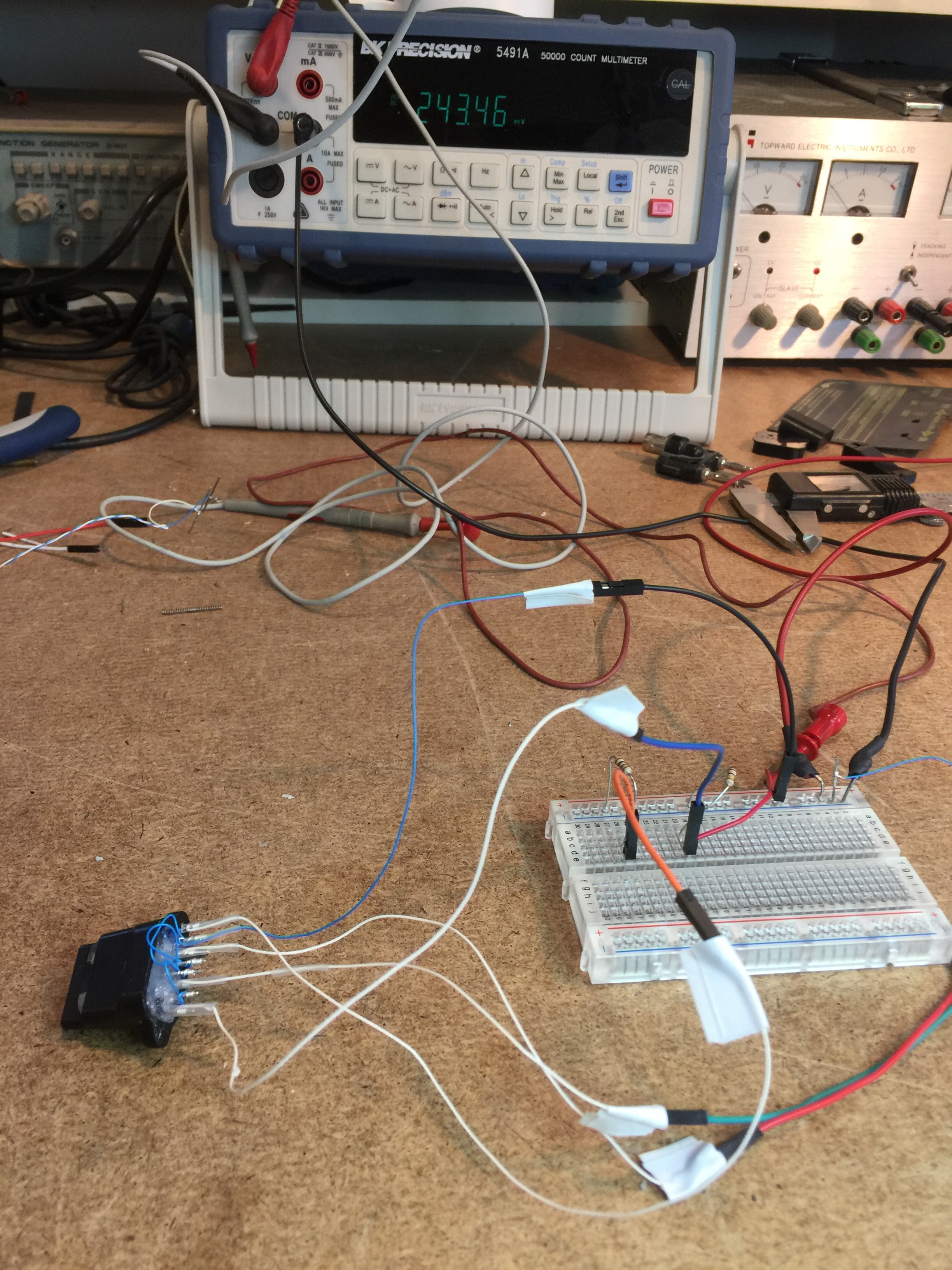 This was the first time trying this significantly changed design since I last worked on the project five years ago. It was a big moment! And it worked perfectly! Amazingly controllable, Of course all that can be seen now are changing voltages from the sensors based on lower lip/jaw and tongue/throat throat position. However for both sensors it's possible to select, hold and repeatably return to a wide range of positions. When mapped to music controllers this should give a great playing experience.


 Michele Perla
 Ultimate Robotics
 oneohm
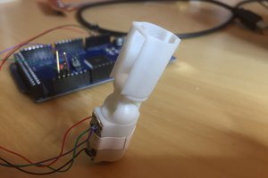
 Tim Wilkinson
Sorry for the long time in not posting. The project transformed last September and I have not been able to write about it until now.
Last September the prototypes were working great but difficult to assemble. The mouthpiece would be too difficult for the majority of hackers to make. It also needed to be smaller which would require tiny surface mount electronics, pick and place assembly and injection molded parts. i.e. It needed to be a manufactured product.
However, I did not have the resources to run a business by myself as it would take me away from the research. Last September I was introduced to Rudy Verpaele of IMOXPLUS https://www.imoxplus.com/site/ by Pedro Eustache http://www.pedroflute.com/.
Rudy was developing an innovative physical modeling synth called Respiro that could benefit from a more expressive electronic mouthpiece. Rudy planned to develop hardware wind controllers when Respiro was completed.
Rudy is in Belgium and I am in Canada and I traveled to Belgium last October. We found we were perfect partners and joined forces. Since then Rudy has been on completing and releasing Respiro I have been redesigning the mouthpiece making it smaller, more powerful and manufacturing-friendly.
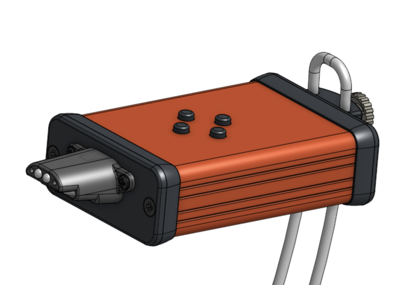
We are now starting to go public with the mouthpiece which we have renamed the Photon because of its use of light in much of its sensing. Here is the first public announcement:
https://www.facebook.com/groups/313247028739320/?multi_permalinks=2467348923329109¬if_id=1564141779424965