• How does it work - Part 2

    Tim Savage07/16/2018 at 13:38 0 comments

    In this part I investigate the high voltage and mechanical side. All of the high voltage circuits are controlled via the relay board MT2F15-4A (while working out a schematic for this board I all filled out all the pin details from Part 1). 

    This board is hard wired into the unit and I didn't really want to remove it, I did however, wire up a quick control mockup on a breadboard and use my bench-top power supply to power the low voltage side. Next I (very carefully!!!) applied mains power to board to determine the exact function of each relay. This also confirmed that all of the heating elements are working and that the motor to raise and lower the lifter runs.

    Missing from this picture is the plastic bracket that sits above the motor frame, this encloses the high voltage relay board. The bracket also provides structural rigidity when the motor is in operation (see the video at the end of this log for it running).

    Next I wanted to understand the wiring of the heating elements, the unit does allow for the outside heating elements to be controlled independently to allow the cooking of crumpets where you don't wish to toast one side as long. Complicating things I discovered that transistor Q5 is a dead short (this was the first control pin I investigated as it controlled the motor). This will need to be replaced, I guess it's about time I took on surface mount components. A lot of care needs to be taken when testing this board there is not a lot of electrical isolation between high and low voltage sides.  
    The outcome is the following schematic describing the operation of the unit. Low voltage side to the left and the mains side on the right.
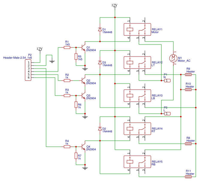
    PinUsage
    1+12V roughly, this is actually the raw voltage out of the rectifier, probably closer to 16V.
    2Ground
    3Centre only, applying 5V turns the outer heating elements off. Controls both NC relays 4 & 5.
    4Motor on, applying 5V turns on the motor. Controls relay 1
    5 & 6Heating elements on. This looks to be a safety feature, both pins require 5V to turn on
    both NO relays 2 & 3. These switch both the Active and Neutral.

    And finally the mechanical motor lift. Note the two limit switches tripped by the rotating cam.

  • How does it work - Part 1

    Tim Savage07/12/2018 at 01:39 0 comments

    With the micro non-responsive it's on to checking if the other components are still working, I've previously determined that the 5V power supply is working, next a check of the various daughter boards to ensure they are all still functioning as well as documenting the functions of each pin.

    Input Board

    First up the input board, this has the code MT2F15-5A and connects to the P2 connector on the main board.

    This board is neatly packaged into a plastic unit that screws into the top of the case providing the input and state display. The clear plastic also doubles as a lightpipe to illuminate the rings around each button.

    Nothing particularly interesting here, all LEDs have current limiting resistors and if you look closely the resistors increase in roughly powers of two to indicate which button is pressed using 2 wires. The design however, only allows for a single buttons pressed state to be determined with the left most button being favoured.

    PinUsage
    1Button +5V
    2Button sense. The measured resistance between pins 1-2 with each button pressed:
    Stop (Toast/Cancel) - 0Ω
    A Bit More - 1KΩ
    Crumpet - 2KΩ
    Defrost - 4KΩ
    Lift And Look - 8KΩ
    No buttons - 18KΩ
    3LED 15
    4LED Common
    5LED 16 & 17
    6LED 19
    7LED 20
    8LED 18
    9LED 21 & 22

    Everything seems good on this board, all the LED's light up and buttons work correctly.

    Read more »

  • Initial investigation

    Tim Savage07/08/2018 at 15:29 0 comments

    First steps were to trouble shoot what was actually wrong with the unit. Prior to stopping working after applying power the unit would turn on all the LEDs and then the progress bar would light fully before rapidly reducing to zero. It was no longer doing anything on power up.

    After removing the case and checking for anything obvious eg anything burnt etc. The first thing I noticed was like any appliance in Sydney (and I'd assume many parts of the world) if it's warm and contains food, it will have signs of cockroaches and this was no exception. However it did seem confined to the crumb trays and the high voltage side. Judging by the few dead roaches they likely didn't survive the toasting cycle. Nothing however, looks to have obviously failed.

    All the internal wiring is high temp fibreglass braided, there is a small transformer that leads to the mainboard along with a number of daughter boards. These a broken up into the main-board that includes the low voltage power supply, a micro and the toast level control, a input/LED board (buttons with lighting), a LED progress bar board and finally a relay board for switching high voltage components.

    A quick test with a multimeter shows that the transformer is good and is putting out ~13V AC. Following "thou shalt check voltages" the AC input is rectified with the raw DC being supplied to the relay board as well as a 5V regulator providing power to the micro. Both of these voltages are present and stable. I also at this point wire up an alternate AC input plug that I can plug into my bench-top AC supply to more safely power the main board.

    After testing various points and giving the unit a good clean it is looking very much like the micro is not working. This rules out a "simple" repair.