There was still a lot I could do with the unit if I hacked it to run as a DC transformer.
- Validate the high-side current sense
- Validate the current sample & hold circuit and develop formulas for input / output current & power
- Validate thermal model against real-world and test thermal management & shutdown
- Measure input ripple current to assist with differential mode input filter design
- Test sine section - both the gate drives & MOSFETs were new for me
- Measure sine performance @ 48kHz
- Test voltage regulation via adjustment of sine table values - critical if I am to pursue a DC transformer version
- Measure sine section EMI footprint and determine how to reduce / contain (I already knew it was bad in part because of a poor PCB layout)
- General refinement of the controller's code
First up was to replace the center-tapped transformer. I used the same core & material (TDK #B64290L0674X087, N87 ferrite). The high voltage secondary of 48 evenly spaced turns was wound against the core using 20AWG with one layer of 3mil polyimide tape. The three-turn primary was wound on top and used 10 strands of 20AWG. This is difficult to work with but like the secondary I try to cover as much of the core as possible. Another layer of 3mil polyimide over the primary and then a three-turn secondary (auxiliary) to power the sine section. This was wound with 24AWG. All magnet wire is MW35-C HY spec. The transformer's resonant frequency tested at 510kHz, with a calculated lumped parasitic capacitance of 4.9nF.
Note that unlike the original design there is no need to power the inverter section; it will draw its power directly from the DC input.
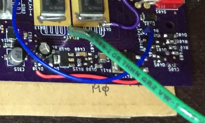
Next the start circuit & LDO had to be bypassed. C405 was replaced with a jumper so pass transistor Q403 remained on. R417, R418, and D407 were left in place for inrush control; these would now remain in circuit during operation but no current would flow due to D407's forward voltage drop. D408 was removed to disconnect the LDO and a jumper placed from the input pin of R417 to D408's cathode pad. With the switch in the ON position the inerter's auxiliary bus would be powered directly from the DC input. This limited the input voltage to < 14V (fans).
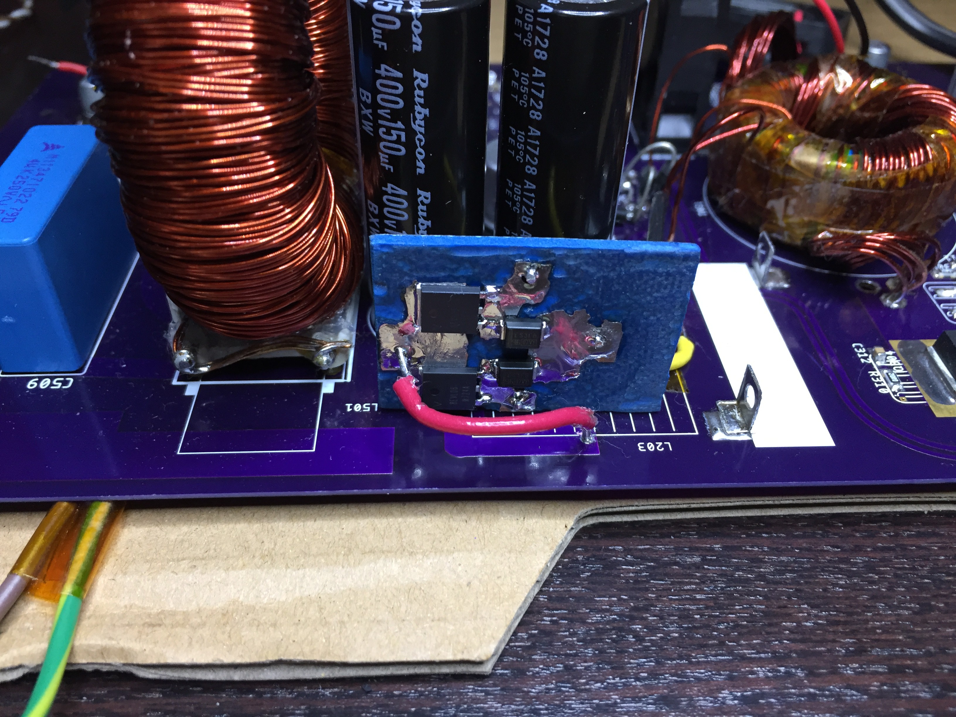
Last, the full-wave rectifiers for the high voltage & sine auxiliaries needed to be replaced with a full-bridge. Not a problem for the auxiliary since it's low voltage. I was able to hack them right on the board.
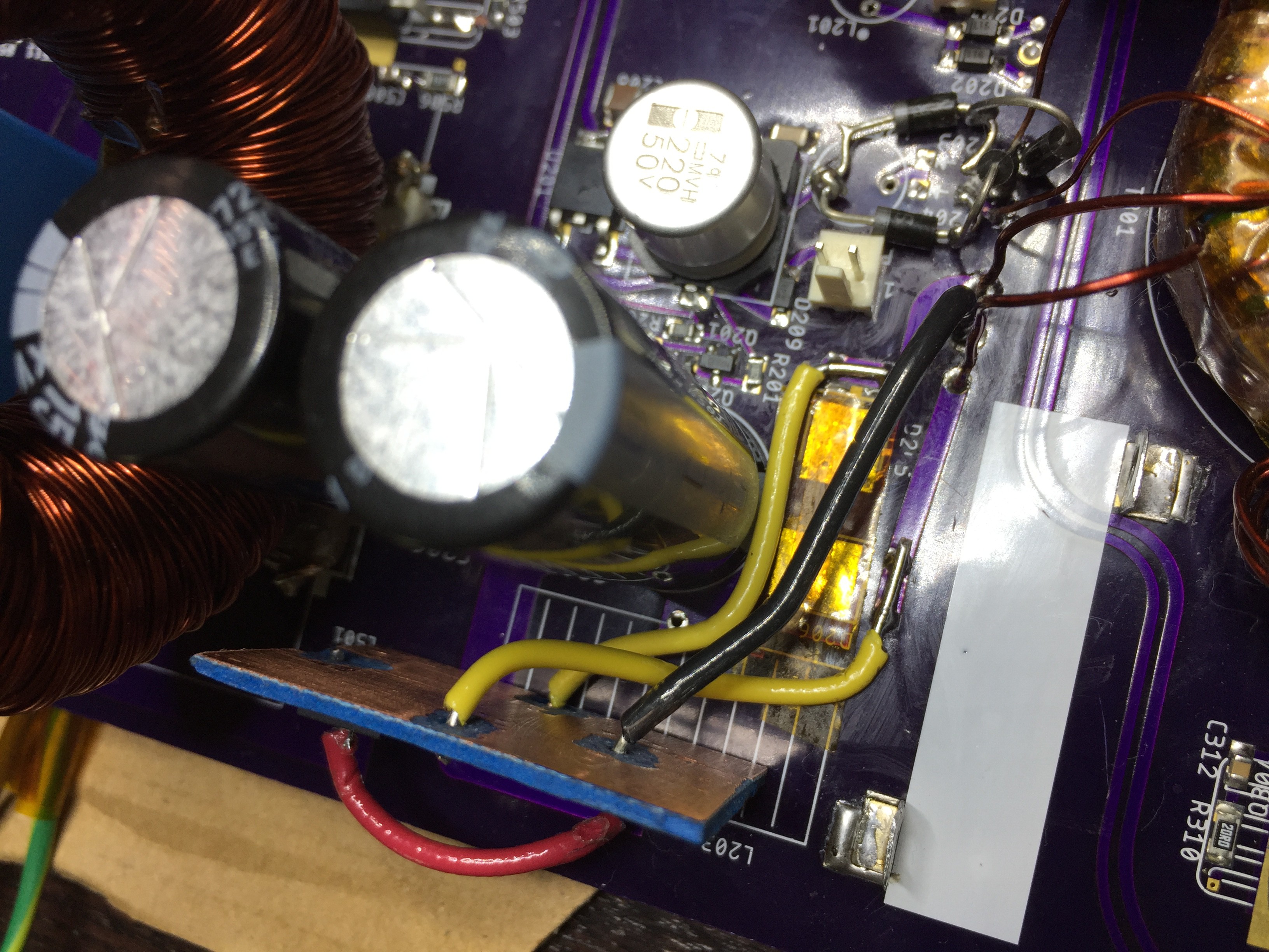
But I didn't have four of the same diodes for the high voltage side so wound up with a split of two each. I used the Dremel to etch a board to mount them on and spliced into the 350's PCB.
Here's a picture of the completed hack setup for testing. The black & yellow leads in the bottom left corner are the AC output. One set of clips leads to an AC true RMS watt meter and AC load, the other to a Tek P5200 high voltage differential probe. The black toroid with the grey clips is a current transformer. The brown & green leads at bottom left are from the high voltage DC bus and connect to an HP 6063B DC load.
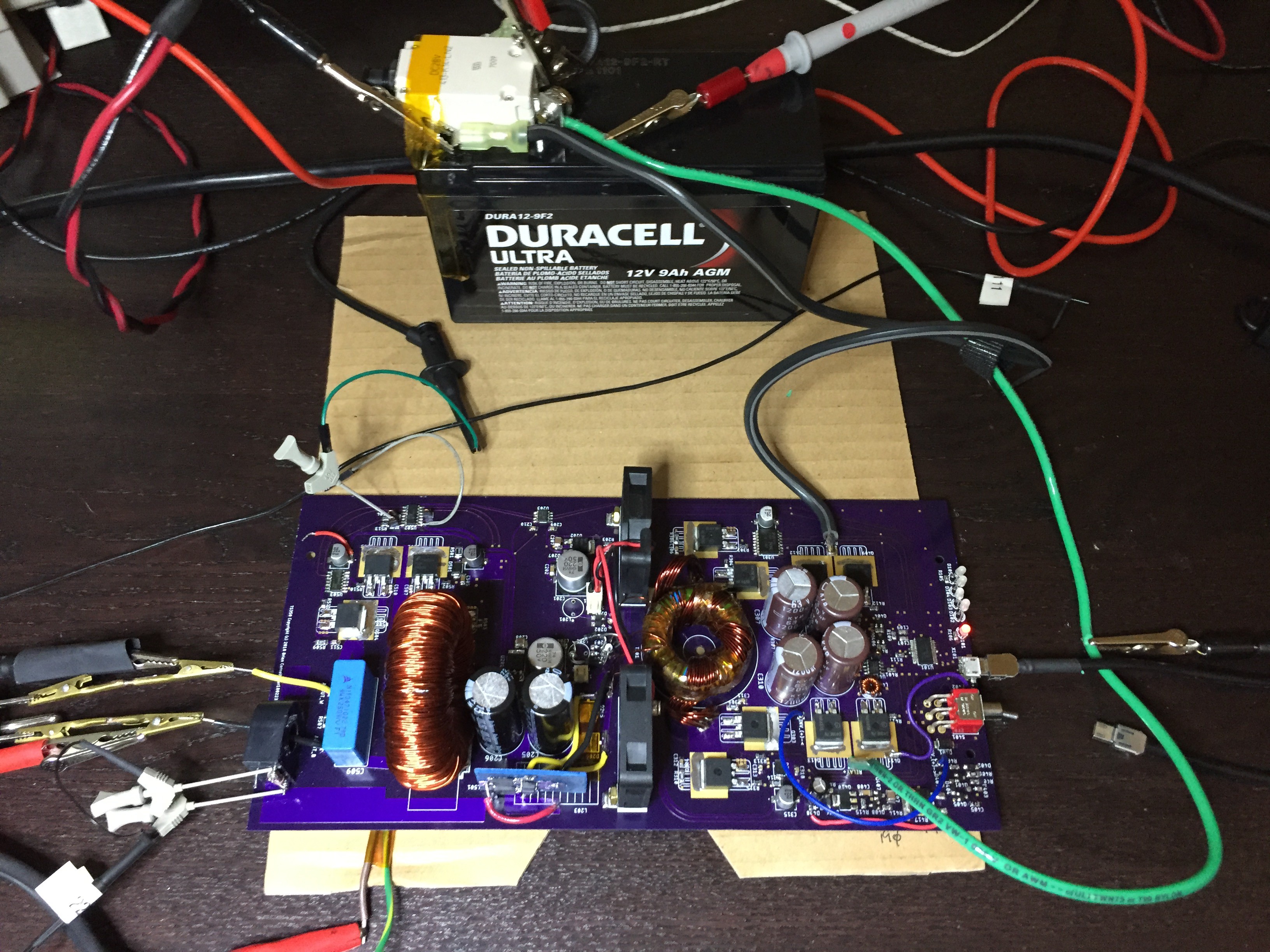
The Duracell battery is 12V, 9Ah. I use it in conjunction with my bench supply which maxes out at 10A. I'll have the bench supply connected to the battery to extend the run-time and to recharge between testing cycles. The inverter will easily draw 30A+ when running close to rated output so cycles are limited to ~ 15 minutes. It's not ideal and takes more time to get things done but you have to get creative without an unlimited budget to buy gear.
On that theme, the red & black alligator clips on the green DC+ lead are used to measure current. My bench meter is limited to 10A. I removed the insulation in two spots about 1 foot apart which gives me ~ 1mV/A for 10AWG.
AC loads: those are hard to find even if you do have the money and they are very expensive. I use an autotransformer connected to a 1300W resistive space heater. I usually put my watt meter in line with it too. The autotransformer allows you to set the load. Transient testing? Sure, flip the load switch.
All of this works great to baseline the unit and make sure it is safe.
Discussions
Become a Hackaday.io Member
Create an account to leave a comment. Already have an account? Log In.