My efforts for salvaging the prototype are immediately rewarded. The DC transformer works great - no ring, clean outputs, decent regulation under load.
I resume testing of the sine section. Beyond some simple validations that it's working one of the first things I'll do is connect it to a 40W incandescent bulb. Not too big of a load but a decent inrush current. And I'll usually flip them on/off a few times to see how it handles the repetitive stress. After two cycles the sine bridge fails.
Testing shows a hi/low MOSFET pair is bad. I give them the benefit of a doubt and write it off to accumulated stress trying to operate with that hideous ring from the original transformer. Replace & retest; now the other side fails.
Hm, now I'm not so sure. I pull the data sheet for the IXYS IXFA30N25X3 MOSFETs.
They are new on the market and I was a bit hesitant when I chose them but their gate charge & switching times were so impressive for what they cost. The Safe Operating Area (SOA) is one of the first things I look at when selecting transistors for power applications. I review it and that's when my heart sinks. Here's why.
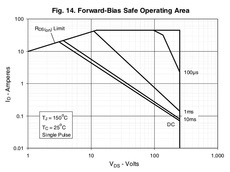
The gradient lines don't render well here but 6A @ 200V intersects on the 100uS line. The time sections decrease by one decade as you move to the top right corner which is only 10uS. With the TS350's rated output the sine bridge switches will see much higher peak currents during turn-on. Don't know what I was smoking when I chose these but they are not right for the unit.
As a general rule, when comparing MOSFETs advertised voltage & current ratings, beware of those with lower gate charges and (typically) faster switching times. They will almost always have a more restrictive SOA. Here's the chart for the Fairchild FDB44N25 I replaced them with:
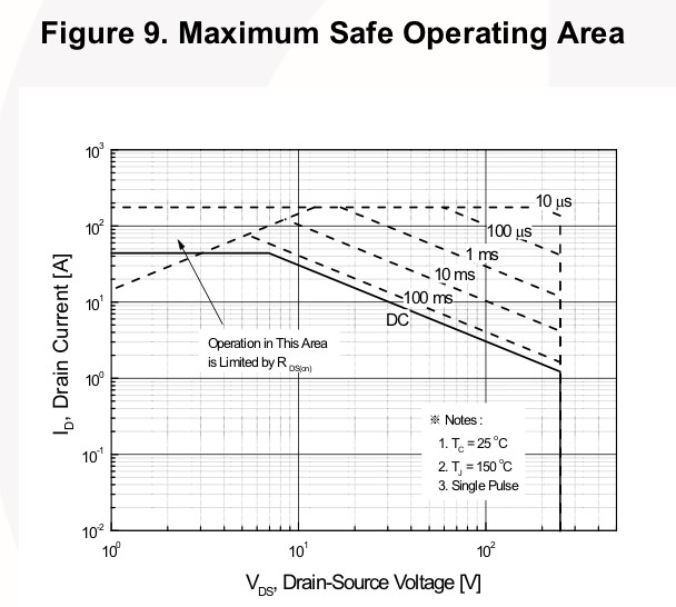
This puppy can handle 50A @ 200V for 100uS! But it's a dog speed wise with max switching times in excess of 100nS vs. 24nS for the IXYS. Same on Qg (gate charge): 61 vs. 21nC. This was all I had on hand and was surprised at how well they performed, especially since I didn't modify the bootstrap or gate drive.
I titled this 'Stranger Things' because I got to witness a MOSFET failure mode that I had not seen before. Prior to swapping all four IXYS MOSFETs I replaced the two that failed with Fairchild's. So one side is running IXYS & the other Fairchild; no mix & match with the gate drivers.
One of the primary tests I'll do on a sine bridge before applying high voltage for the first time is to run it from a bench supply with 10~20V applied to the bridge. First open and then with a resistive load of 1 ~ 2A. I did this with the repair and all was good. I then powered the inverter and proceeded with tests.
I began noticing distortion in one half of the sine - not surprisingly it was the IXYS side of the bridge. I spent hours on it chasing a ghost. Random gate drive & source voltages on the high side MOSFET would show no gate pulse or MOSFET turn-on. It was inconsistent and didn't seem to vary with load. For a while I thought it was the gate driver. Ultimately I replaced the transistors and the problem disappeared.
So the symptom was random gate shorting to the source but no short from the drain (which would have tripped over-current). The typical failure mode is a shorted D-S and sometimes D-S-G, and sometimes just open. But not random failures to switch at higher voltage stresses.
Okay, crisis averted, lessons learned, now I can move on.
Discussions
Become a Hackaday.io Member
Create an account to leave a comment. Already have an account? Log In.