With a functioning unit I can get on with using it to explore refinements for the next design iteration. But a lot of that work requires being able to measure, with reasonable accuracy, the input current. And therein lies the rub: this thing can easily draw 40A RMS with peaks exceeding 50A. I had mentioned in a previous post using the voltage drop across a measured segment of the positive supply lead but that is prone to noise and temperature error, particularly when using the scope.
Bench equipment to do this is prohibitively expensive. So are scope probes - most can't handle currents this high. I could replicate a version of the sense resistor & opamp circuit in the TS350 but that is exactly what I am trying to calibrate (for average power measurements).
Allegro hall effect current sensors to the rescue. I've used these before and they're great for applications requiring accuracy but without a high dv/dt and they are very rugged. I selected the 50A DC ACS770LCB-050U-PFF-T. For about $10 and some elbow grease I have an accurate input current sense that will render a reasonable picture of the current ripple. Response / rise times are on the order of ~ 6uS.
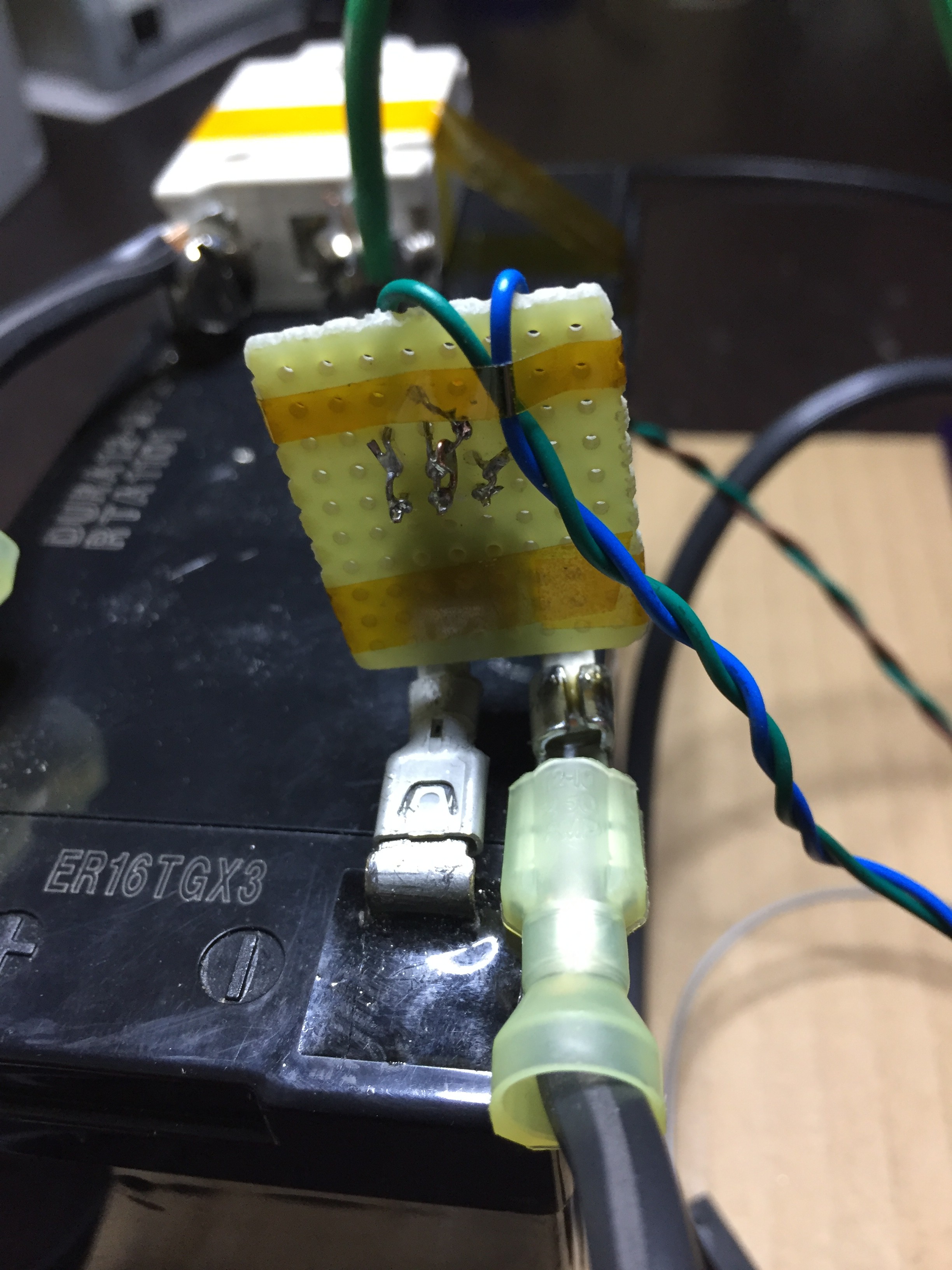
Here's a picture of the setup:
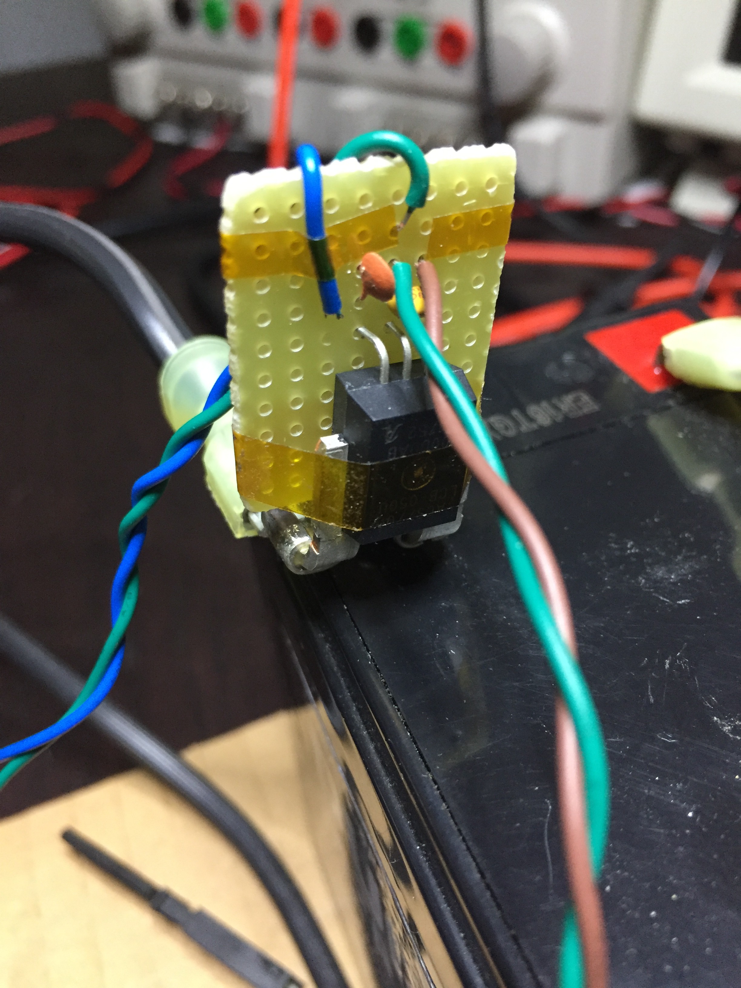
The sensor is fastened to perf board to facilitate power & output connections along with the decoupling and output filter caps. The current sense leads (PFF leadform) are connected to female clam connectors for direct connection to the battery negative and return lead from the inverter.
And here's the full setup:
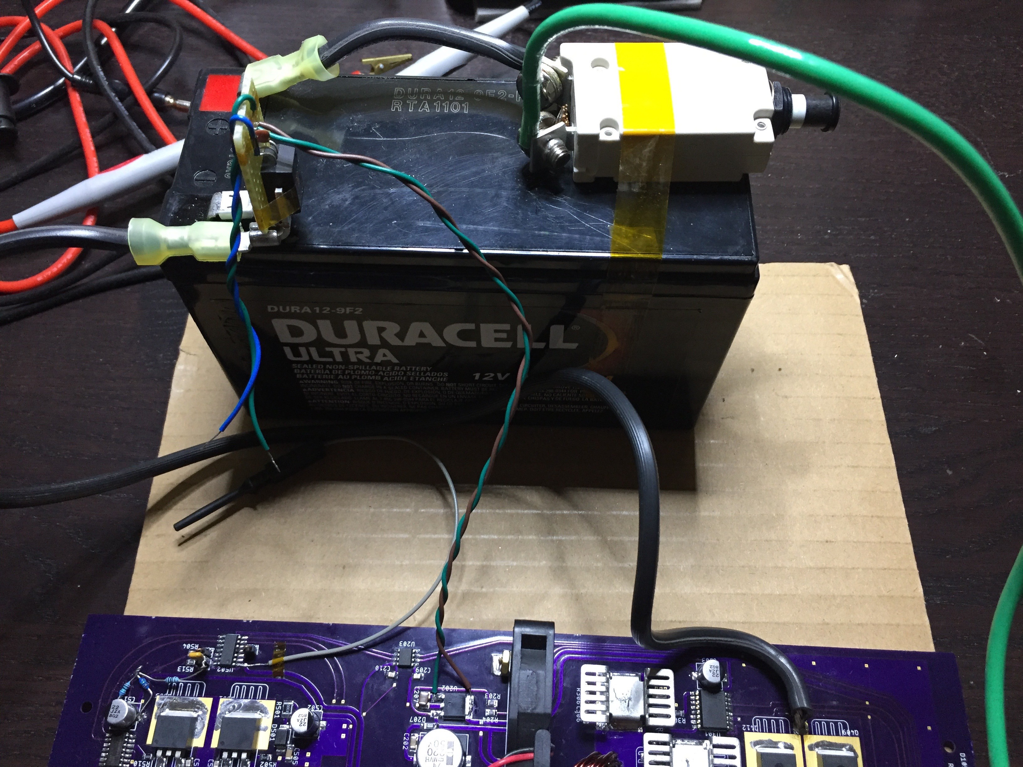
The sensor requires a 5V supply and this is taken directly from the unit's 5V LDO (green/brown pair). Sensor output is the blue/green pair.
A nice side-benefit of these sensors is galvanic isolation; not critical for this application but does help keep the noise down. And noise is another great feature - the lack thereof. Below is a trace showing the current ripple AC component with a 400W DC load on the inverter's high voltage section.
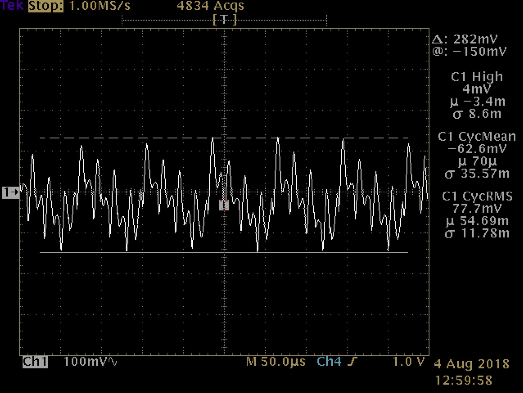
The sensor's resolution is 80mV/A which gives a ripple component of about 1A RMS.
Discussions
Become a Hackaday.io Member
Create an account to leave a comment. Already have an account? Log In.