 Wasim Sahu
Introduction
Hi dear hackday I hope you will be fine today. I am presenting a project about power generation with the movement of steps. It has 3 phases. First will be with piezoelectric, second will be with hand harvesting flash light that has dc gear motor and third will be a advance with elastic piezoelectric. I use the 3 phases to suite you. Which level of hardware you have. Basic normal and advance. Have you ever had that moment when you had a very important text to send, but before you could finish sending it, your phone died? Pretty much any person with a mobile phone/device has experienced that frustrating moment when a device fails to complete its task due to a lack of energy. My project is designed to fix this problem in a way that promotes health by creating a shoe insole that converts the physical energy created by walking into electricity, which is then stored in a portable battery pack. This way, you will always have an emergency power source (and you will be renewing some of your own physical energy too)
Aim of the Project
The aim of our project is to build a system that can generate power from that energy and use it. My project is extremely simple but highly useful. This system when applied on large scale can generate very high amount of power this power then can be used for upliftment of the civilization.
Phase 1
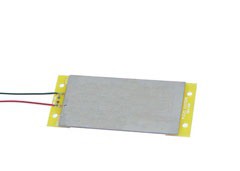
Energy Harvesting using Piezoelectric Materials
Parul Dhinga from dept. of E.C.E of M.I.T Manipal has explained theoretical model for energy harvesting system using piezoelectric materials have been presented. It is evident that harnessing energy through piezoelectric materials provider a cleaner way of powering lighting systems and other equipment. It is a new approach to lead the world into implementing greener technologies that are aimed at protecting the environment. Piezoelectric energy harvesting systems are a onetime installment and they require very less maintenance, making them cost efficient. One of the limitations of this technology is that its implementation is not feasible in sparsely populated areas as the foot traffic is very low in such areas. Further experimentation has to be carried out for its implementation on a larger scale.
PARTS AND TOOLS
The following lists are divided into 2 categories. The first category consists of things you NEED to complete the project, while the other list consists of things that are very HELPFUL.
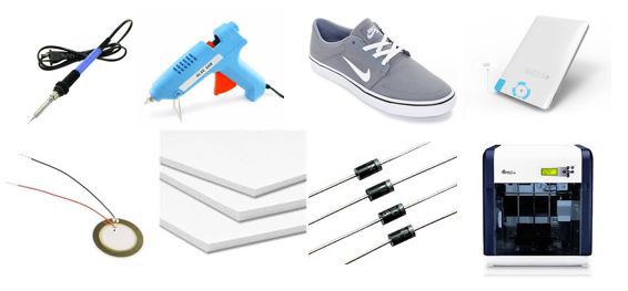
Things that you NEED:
- Shoes (duh!)
- Piezo electric elements (x14) I found 15 of them for 15.99
- Rechargeable battery pack w/ charger(x1) I got mine from 5 and Below for 5$
- Hot glue gun w/ hot glue
- Soldering iron + solder
- Foam/cardboard/anything you can squish (I used foam board that I got for 1$)
- Access to a 3D printer (If you do not have access to a 3D printer, you can always substitute a different material/plastic, but my instructions will be based off the 3D printed design
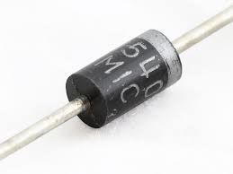
- 1n4001 - 1N4007 Diodes (x4) OR a CFL lightbulb, which I will show you how to take apart in order to salvage diodes needed for this project.
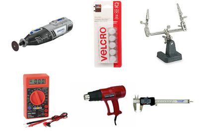
Things those are helpful:
- Dremel tool
- Helping hands
- Velcro strips (HIGHLY RECOMMENDED!)
- Multimeter
- heat gun (if taking apart CFL bulb)
- ruler/caliper
HOW DOES IT WORK?!
In order to fully appreciate the science behind this project, it is helpful to understand how it works. Essentially, the main power source that makes this project possible is something called a piezoelectric transducer (I know, its a mouthful). Piezo electric transducers, or piezo elements, are comprised of materials such as crystals and certain ceramics that have a special property which allows them to convert physical energy into AC electricity. Fortunately, we can take advantage of this special property by putting piezo elements underneath our feet in such a way that every time we take a step, we are using our weight to push on the piezo electric elements- which then in turn convert that energy into electricity. The only issue with this, however is that we need DC, not AC in order to power our stuff. We can solve this problem by creating a bridge rectifier with diodes to convert the AC power to DC power we can use.
MEASURING YOUR SHOE AND PRINTING THE FILE
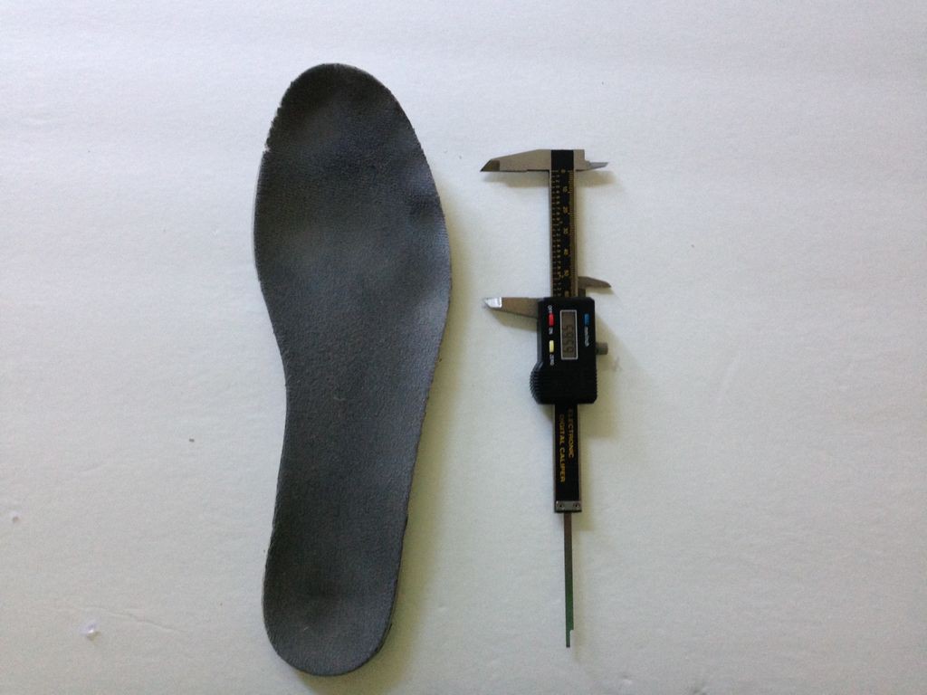
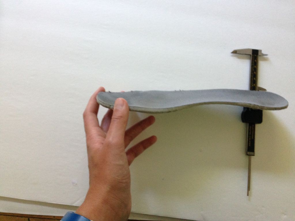
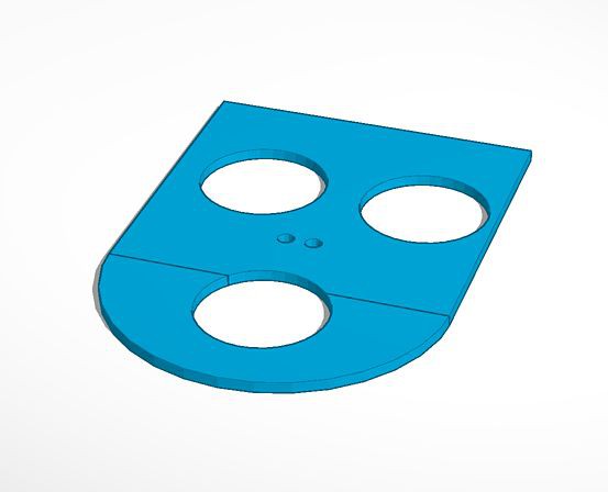
In order to make our piezoelectric generator, we are going to need a plastic base. I have provided the links to my tinker cad files below. Feel free to customize them to suit your needs/foot measurements. The piezo element holes are strategically placed so that they line up with the large indents on my shoe's insole, which indicate the areas of most pressure. These files are based off of my foot, which is a size US 9.5. Although my heel piece fit perfectly, my toe piece required a good bit of sanding in order to get it to fit properly.
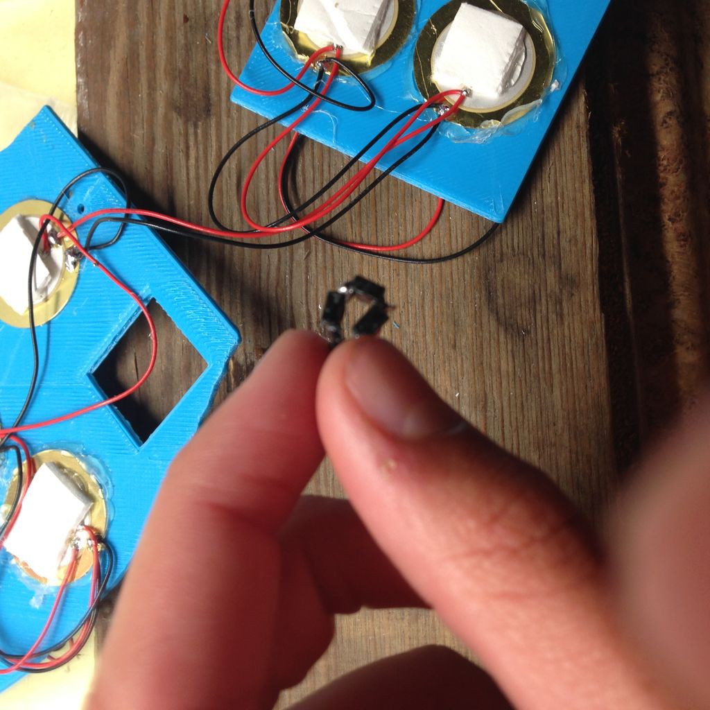
GLUING THE PIEZO ELEMENTS
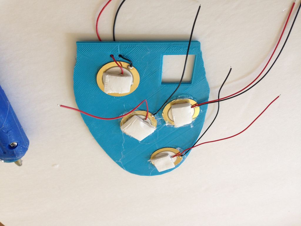
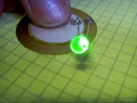
Once we have finished creating the base for our piezoelectric generator, its time to hot glue them on. I found that the best technique to glue the elements to the board was to apply a thin layer of glue around the edge of the hole in the plastic, then quickly pressing the piezo element onto the glue before it cools. Be careful not to apply too much glue, or else you may restrict the foam pads (which will be glued on top of the piezo elements) from fully compressing. Also, make sure the glue does not cover the contact points of the black or red wires, because we will be soldering to these points soon. Make sure you glue piezo elements on both sides of the plastic. If you have a multi-meter, you can ensure that your piezo elements work by setting the multi-meter to AC volts and pressing on the piezo. After you have glued all of the piezo in their appropriate spots, you can then glue the foam/cardboard pieces onto each piezo element.
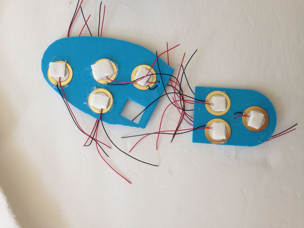
SOLDERING THE PIEZO ELEMENTS TOGETHER
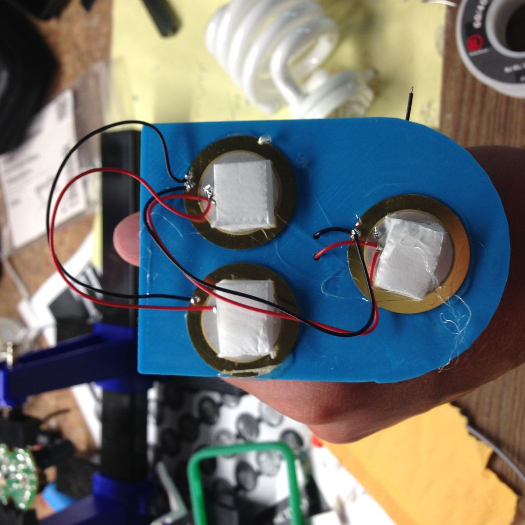
Although piezo elements generate plenty of voltage, they do not generate many amps. We can solve this issue by wiring the all the piezo elements in parallel (in other words, the positives are always soldered to each other and the negatives are always soldered to each other). In this way, we will be able to increase the amount of amps and consequently charge our devices faster. In order to prevent wires from braking off of the solder joints, use hot glue to fasten part of the wire in place so that the stress on the wires is not enacted upon the solder joint. You can connect the piezo elements from one side of the plastic to the other by threading the wires of one of the piezo elements through the holes so that they can be soldered in parallel to a piezo on the other side. Once all of the piezo elements on the heel piece are wired in parallel, solder the last piezo in the chain to one of the piezo elements on the toe piece, and continue to solder the piezos in parallel until all 14 elements are connected.
TAKING APART CFL BULB FOR PARTS
NOTE: If you already have your diodes, you can skip this step!
If you are like me in that you do not have diodes lying around, have no fear! You can find perfectly good diodes inside of your old, broken CFL bulbs in your house. Here is how you do it:
CAUTION: CFL BULBS CONTAIN MERCURY AND OTHER POISONOUS MATERIALS WITHIN THEIR GLASS TUBES. DO NOT BREAK THESE TUBES!
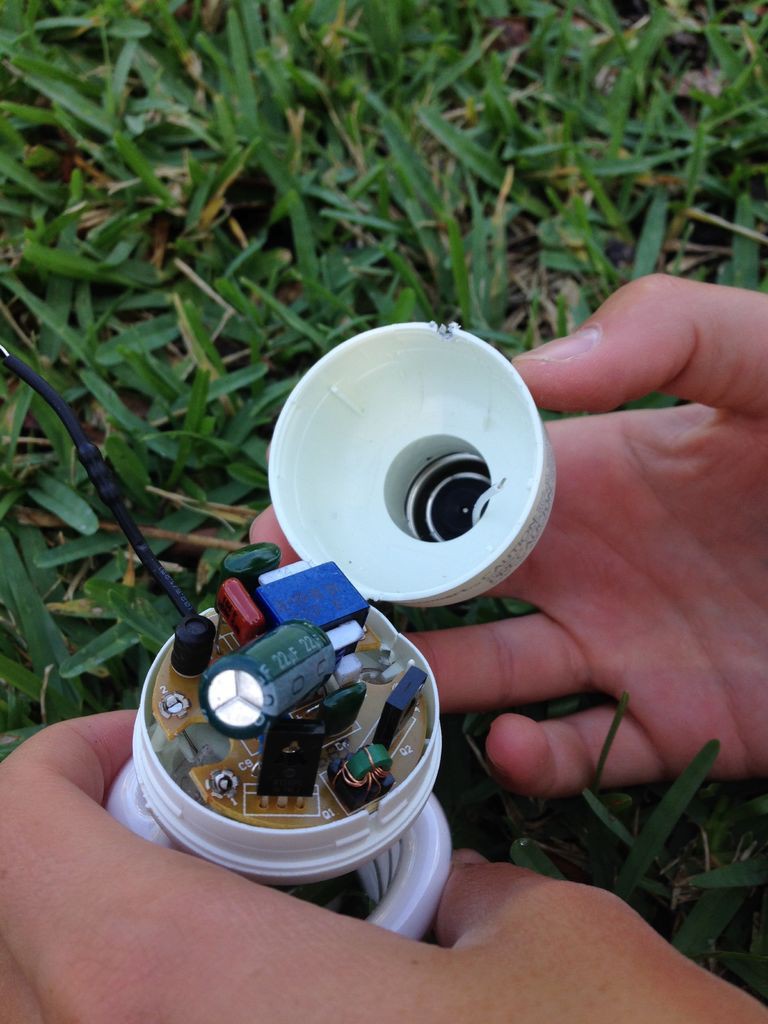
- Go outside with a screwdriver or some sort of tool capable of prying things apart, and sit in the grass or some other soft material. By doing this, you can significantly lower your chances of braking the glass tube, which contains poisonous substances that you don't want to mess with.
- Locate the seam by which the two plastic halves of the CFL bulb are connected, and begin to carefully pry the two pieces apart with your screwdriver.
- Once the bulb has split apart, you will notice that the PCB inside is being held back by two wires connected to the light bulb’s metal base. You can either cut these off like a civilized person or do what I did, which was to continually pull until the wires broke off.
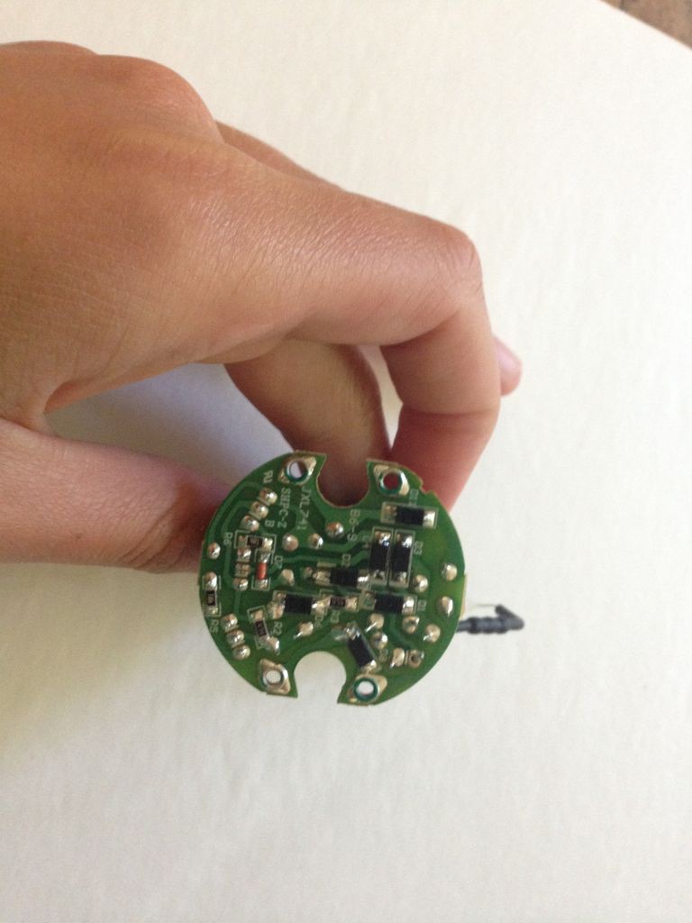
- Most likely, your CFL bulb will contain 6-8 round, black diodes with gray stripes on them to indicate their positive ends. However, if you are like me, your diodes are rectangular prisms, not round, and have engravings on one end to mark the positive side.
- Once you have located the diodes, you can take them off by heating up the solder with your soldering iron and pulling the diodes away. If you have a heat gun, you can take the diode off much easier by applying heat all around the diode so both sides of the diode can be pulled away at the same time. Remember, you only need to get 4 of the diodes in order to create our AC to DC converter.
BUILDING/WIRING THE BRIDGE RECTIFIER
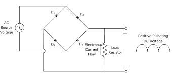

BUILDING THE BRIDGE RECTIFIER:
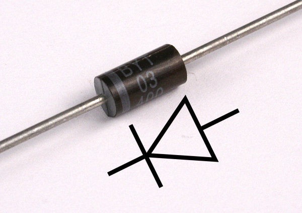
Ok, so for those of you who do not know how to read a circuit diagram, those 4 line segments with arrows on them represent diodes. The arrows always point to the side of the diode that is marked, also known as the positive side. If you have small, rectangular diodes like me, the positive sides are not marked by coloration, but rather small, engraved lines/notches. By following this diagram, you should be able to create the bridge diode.
WIRING THE BRIDGE RECTIFIER:
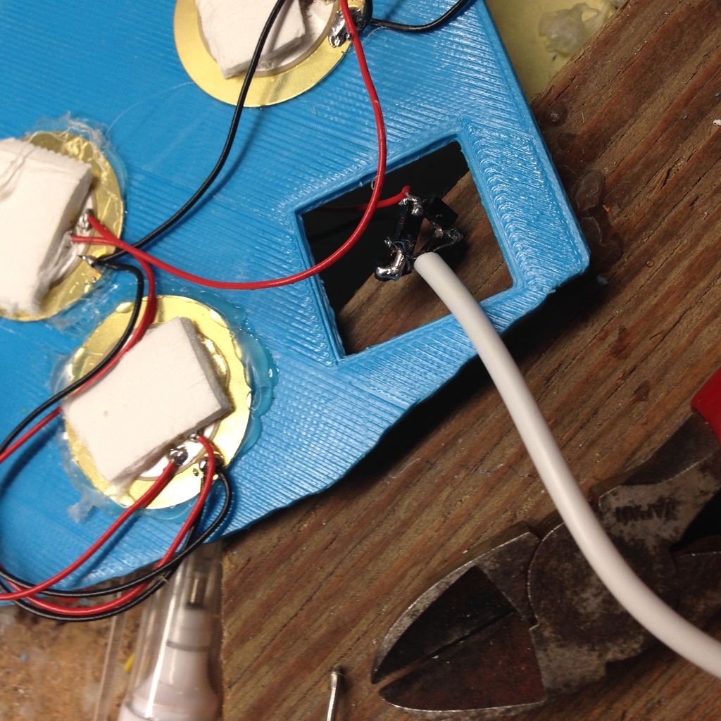
- Wire the piezo element wires to the bridge diode according to the circuit diagram. Since the current is AC, the position of the wires are interchangeable, as long as they connect to the correct diodes in the diagram.
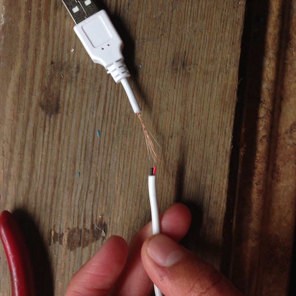
- Strip the usb charge cable that came with your battery pack to reveal the internal wires.
- For the purpose of this project, we will only need the red and black wires, so strip those as well.
- Twist the frayed wire strands of each wire, and tin them with solder
- Solder the wires to the bridge diode accordingly. Be sure to check polarity since DC voltage has positive and negative terminals.
- Hot glue the connections to prevent the wires from breaking off.
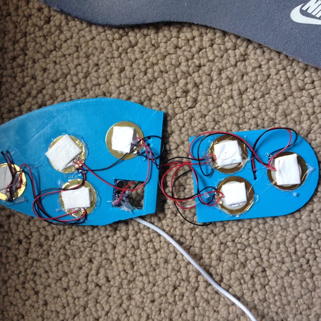
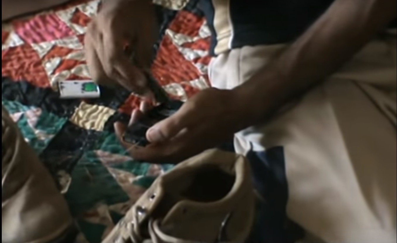
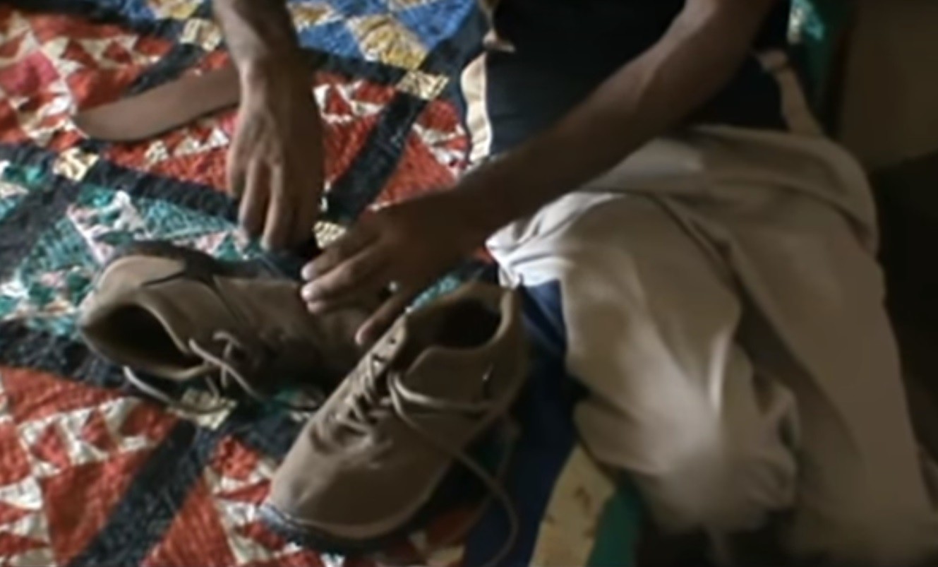
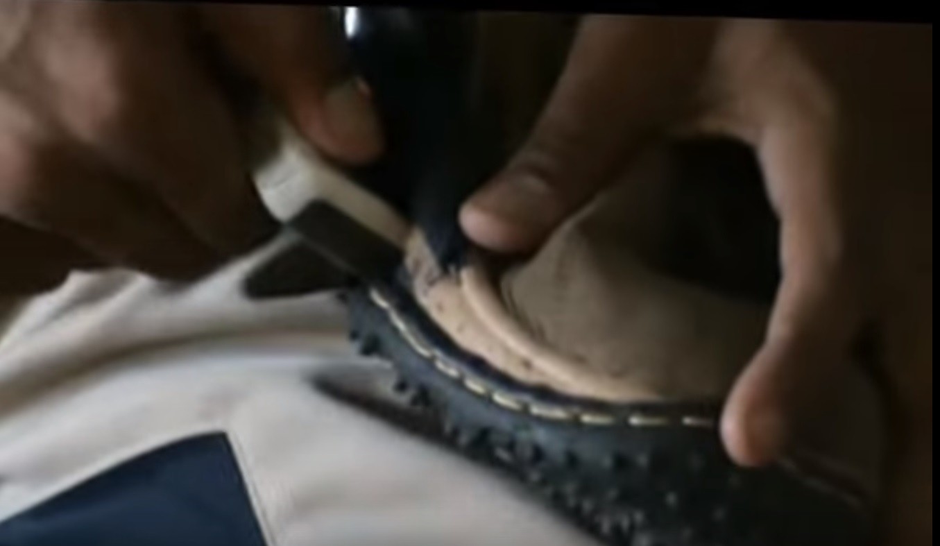
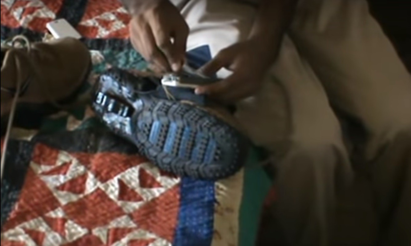
INSTALLATION AND FINISHING TOUCHES
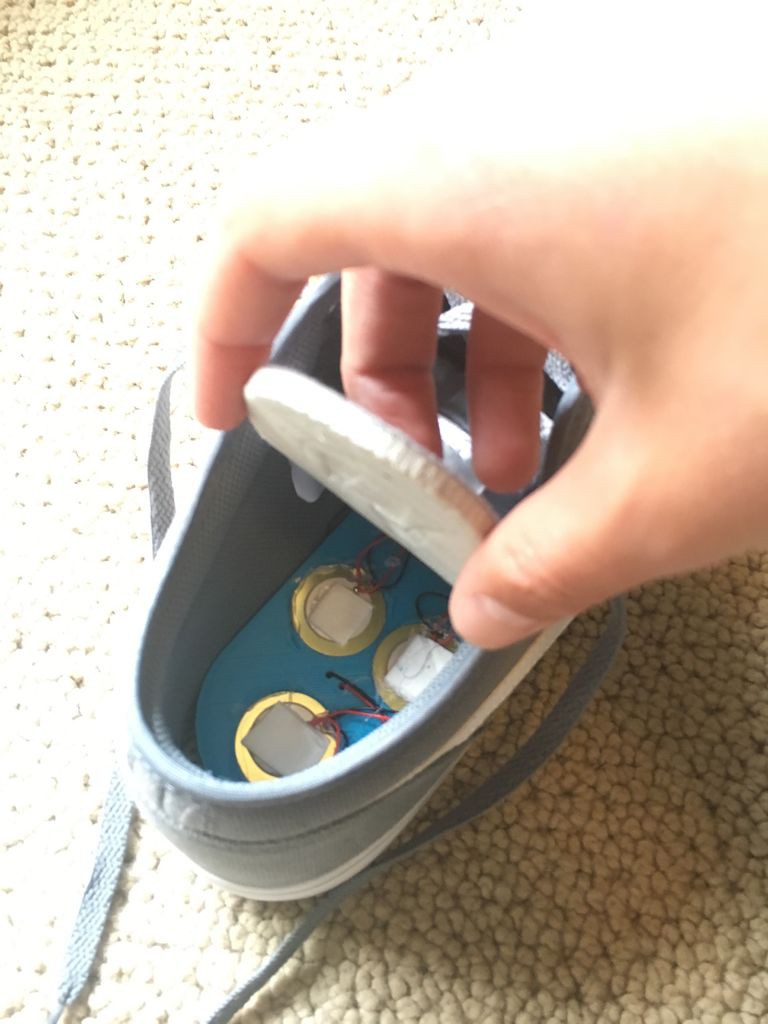
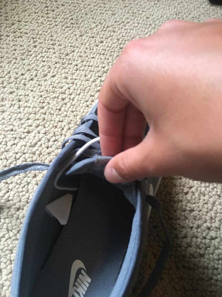
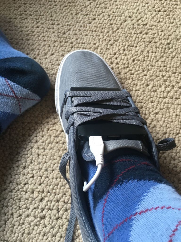
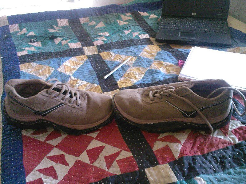
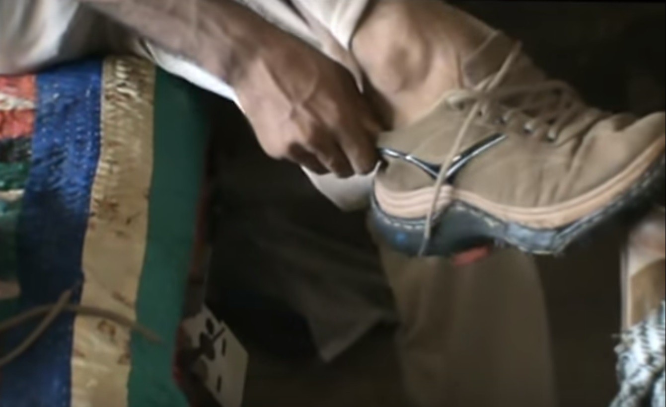
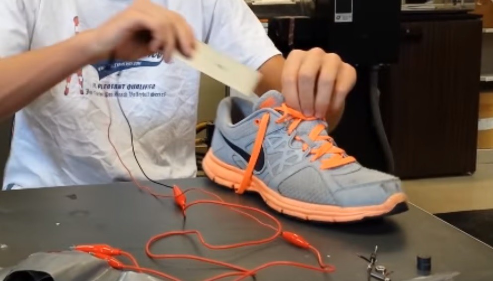
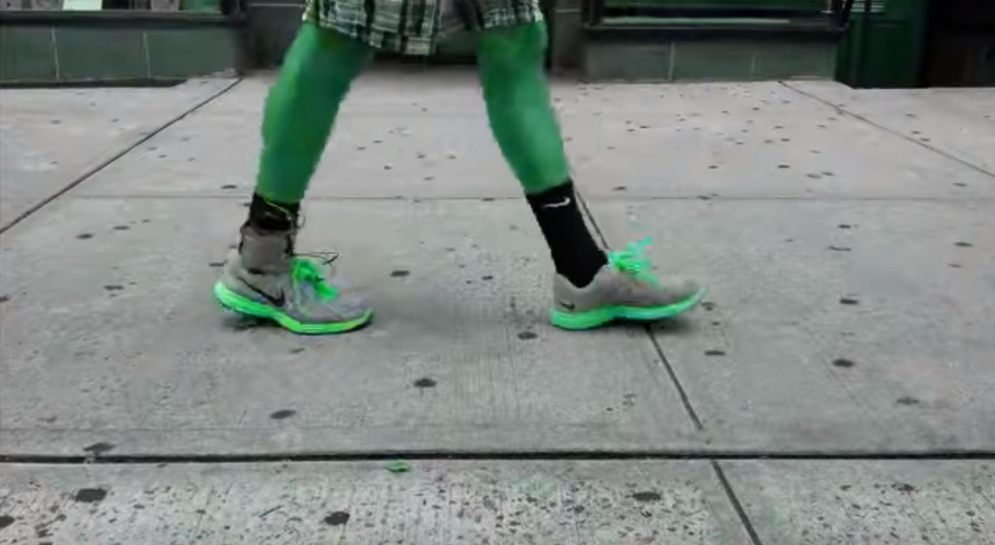
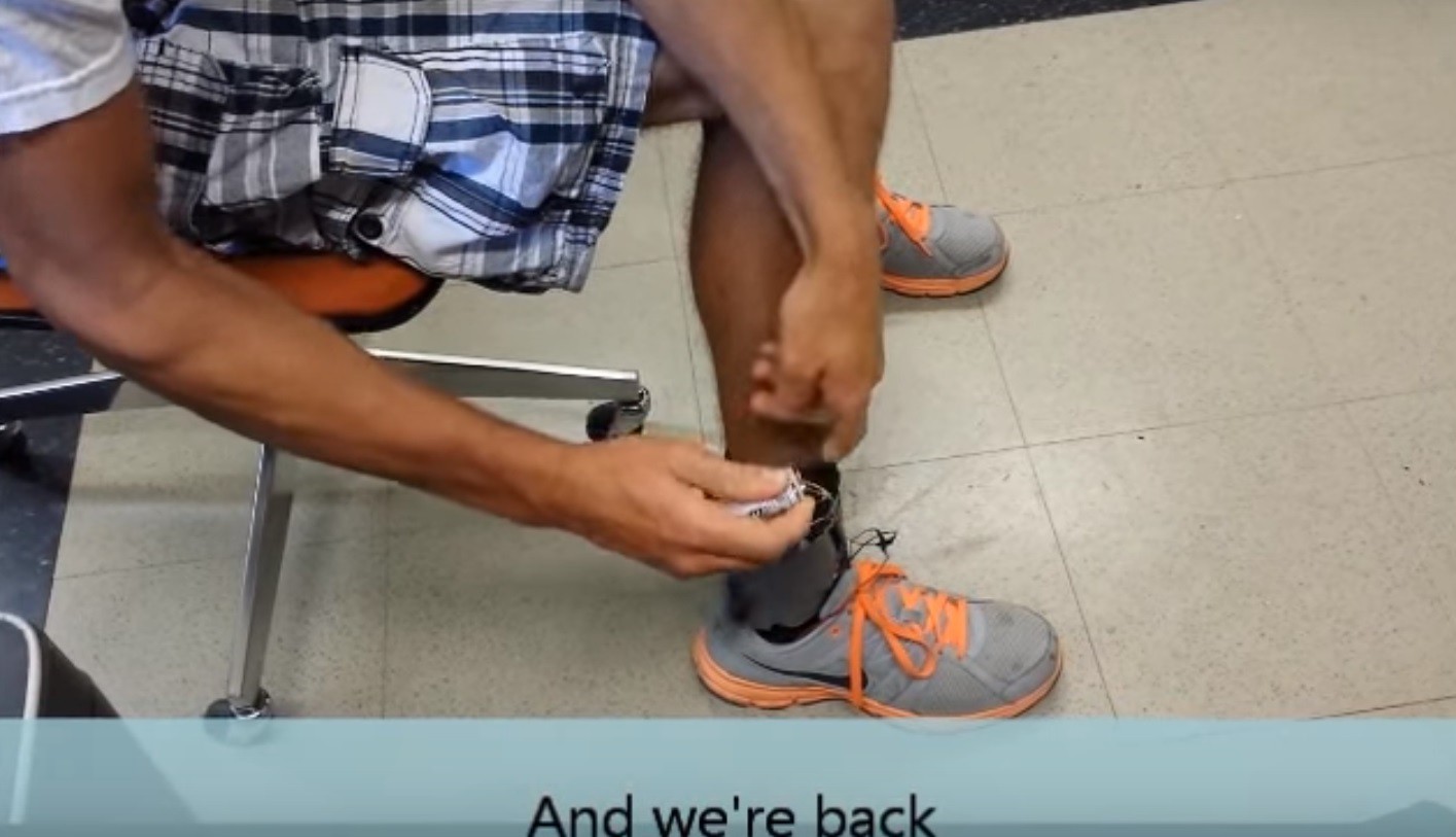
Once we have finished wiring the piezoelectric generator, we are ready to install it! All you need to do is slip the plastic piezoelectric generator inside of your shoe, then insert the original sole on top of it. Take the USB cable wired previously and thread it between tongue and the outside of your shoe as shown in the pictures above. In order to mount the battery, stick it between the tongue of the shoe and the laces and tie your shoes tightly. If you have Velcro, I would recommend using it to better fasten the battery pack to prevent it from falling out while running. I would also recommend making a foam cutout of your other shoe's sole so you can use it as a riser in your shoe with no generator in it. I used my shoe that did not have a piezoelectric generator in it as a storage for my mobile device's charge cable, so I will always have everything I need for charging.
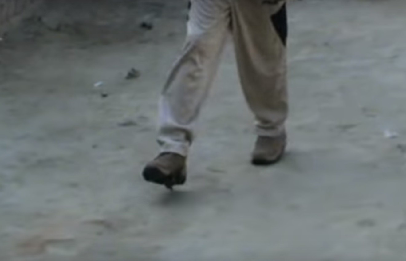
EXERCISE!

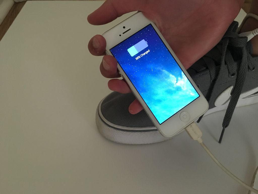
Now that you have finished your electricity generating shoes, there is only one way to see how well they work- EXERCISE! By taking a walk, hiking, or playing a sport for several hours, you should be a able to conduct enough electricity to charge your mobile device. Keep in mind that your battery only charges when ever you take a step, so it should take a while to get a good charge on your battery.
Phase 2
Parts and Tools
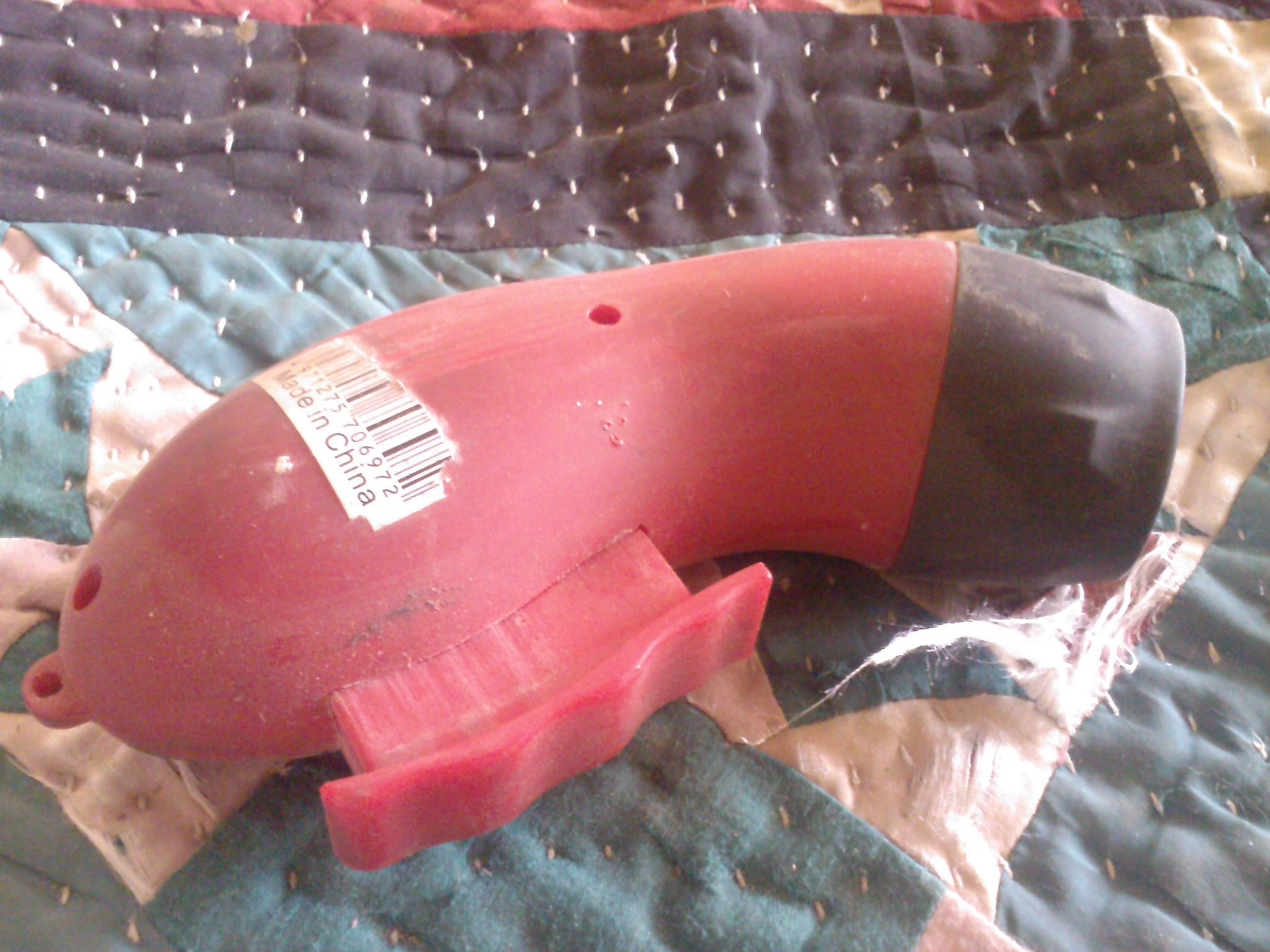
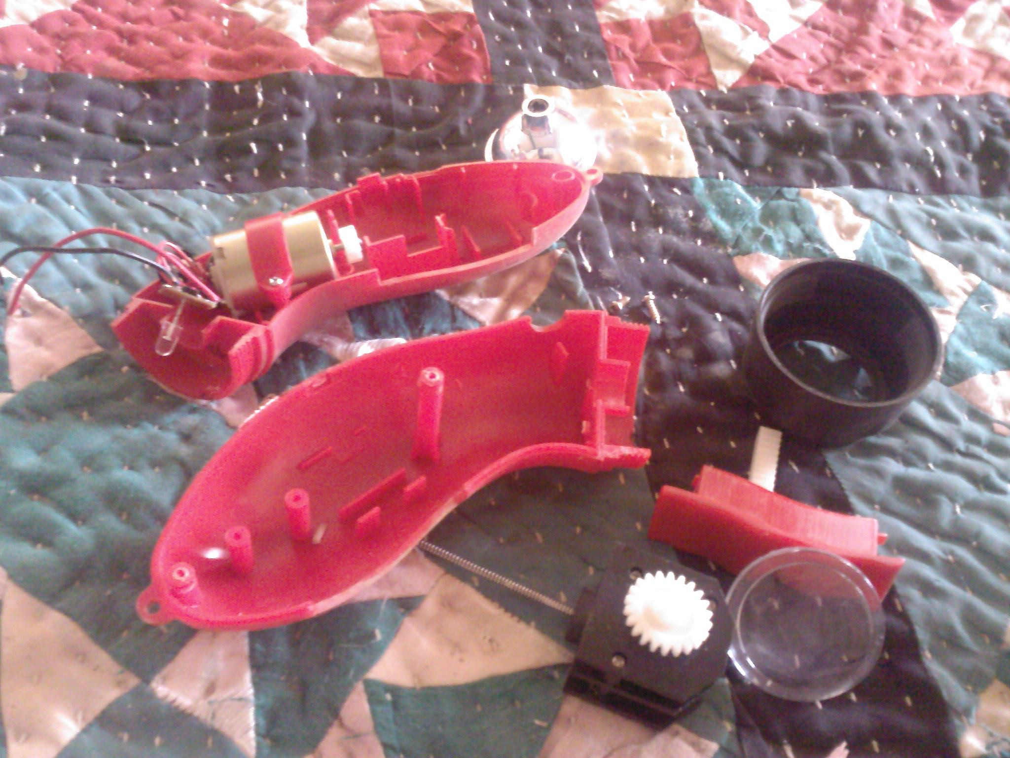
This phase too easy as compares to others. Tools that you need can be use from phase 1. For parts needed a hand power harvesting torch. It has all things that you need charging system and also rechargeable battery. Simply fix it in both pair.
Old Cell Phone and Its Battery (Optional)
You need two old dead cell phone.These phone do not work but are very use full for us. Put its battery in phone. Connect the Battery wire from phone to hand harvesting torch. Put the cell phone with battery in the shoes.
Ready to Go
Now you can use them walk, running, exercise or for games like football, hockey
or cricket.
Phase 3 (advance materials )
Elastic Piezoelectric
Description:
When a piezoceramic trandsucer is stressed mechanically by a force, its electrodes receive a charge that tends to counteract the imposed strain. This charge may be collected, stored and delivered to power electrical circuits or processors.
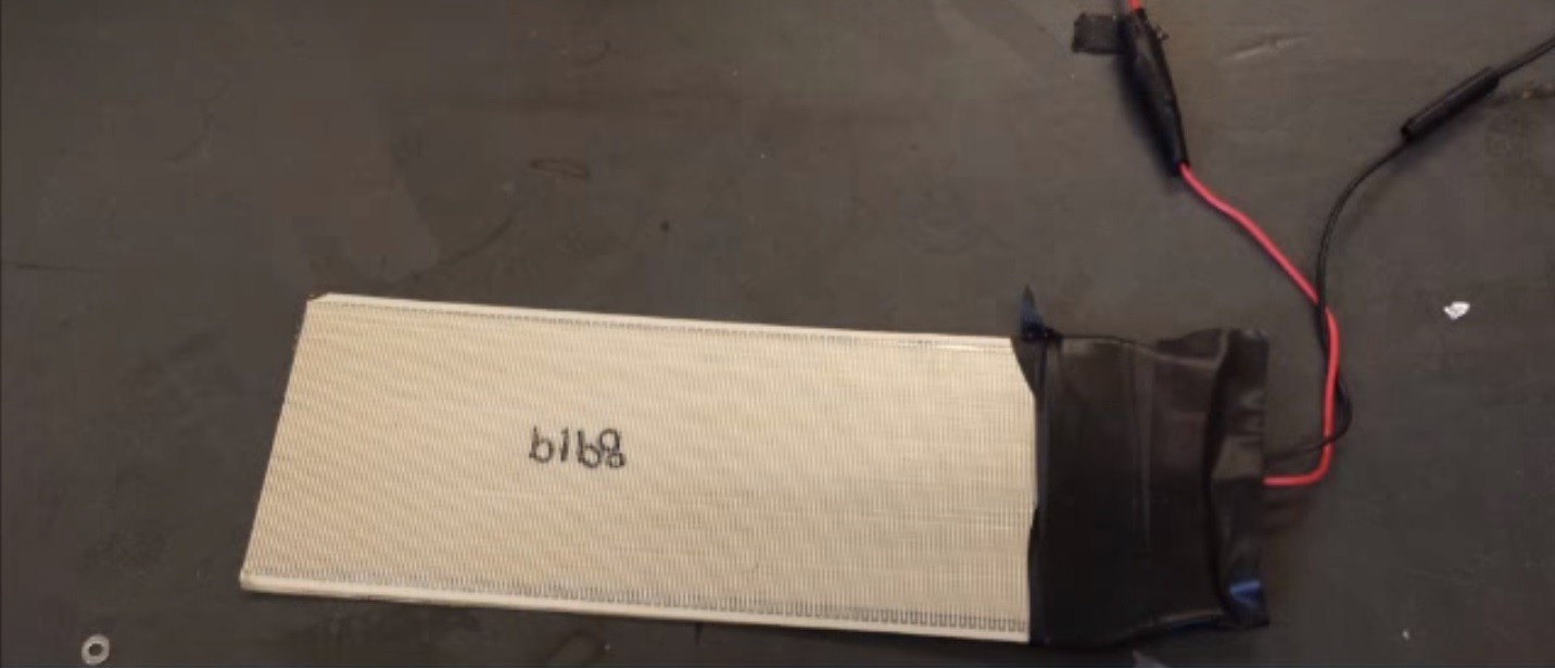
The Piezo Bending Generator
When the Energy Harvesting Bender is flexed, one layer is compressed while the other is stretched, resulting in power generation. It may be excited by intermittent pulses or continuously from low frequency to resonant frequency (where rated displacement is achieved at the lowest force level). The Energy Harvesting Bender is a pre-mounted and pre-wired Double Quick-Mount Bending Generator designed to attach easily to sources of mechanical strain. Its double ended design lends itself to being mounted either as a cantilever or a simple beam. Dimensions for the standard -503 size Double Quick-Mounts are shown below.
Piezo Energy Harvesting Circuit
The self powered Piezo Energy Harvesting Circuit collects intermittent or continuous energy input from the piezo generator and efficiently stores their associated energy in an on-board capacitor bank. During the charging process, the capacitor voltage is continuously monitored. When it reaches 5.2V the module output is enabled to supply power to an external (user) load. At this point 55 mJ of energy are available. When generator energy input is high, the output voltage remains ON continuously. Capacitor voltage is clamped at 6.8V. If external power demand exceeds generation, the output voltage decreases. When the output voltage drops to 3.1V, power to the load is switched OFF and is not turned on again until the capacitor bank has been recharged to 5.2V. The circuit accepts input voltages from 0V to ±500V AC or DC and input currents to 400 mA.
Parts and tools
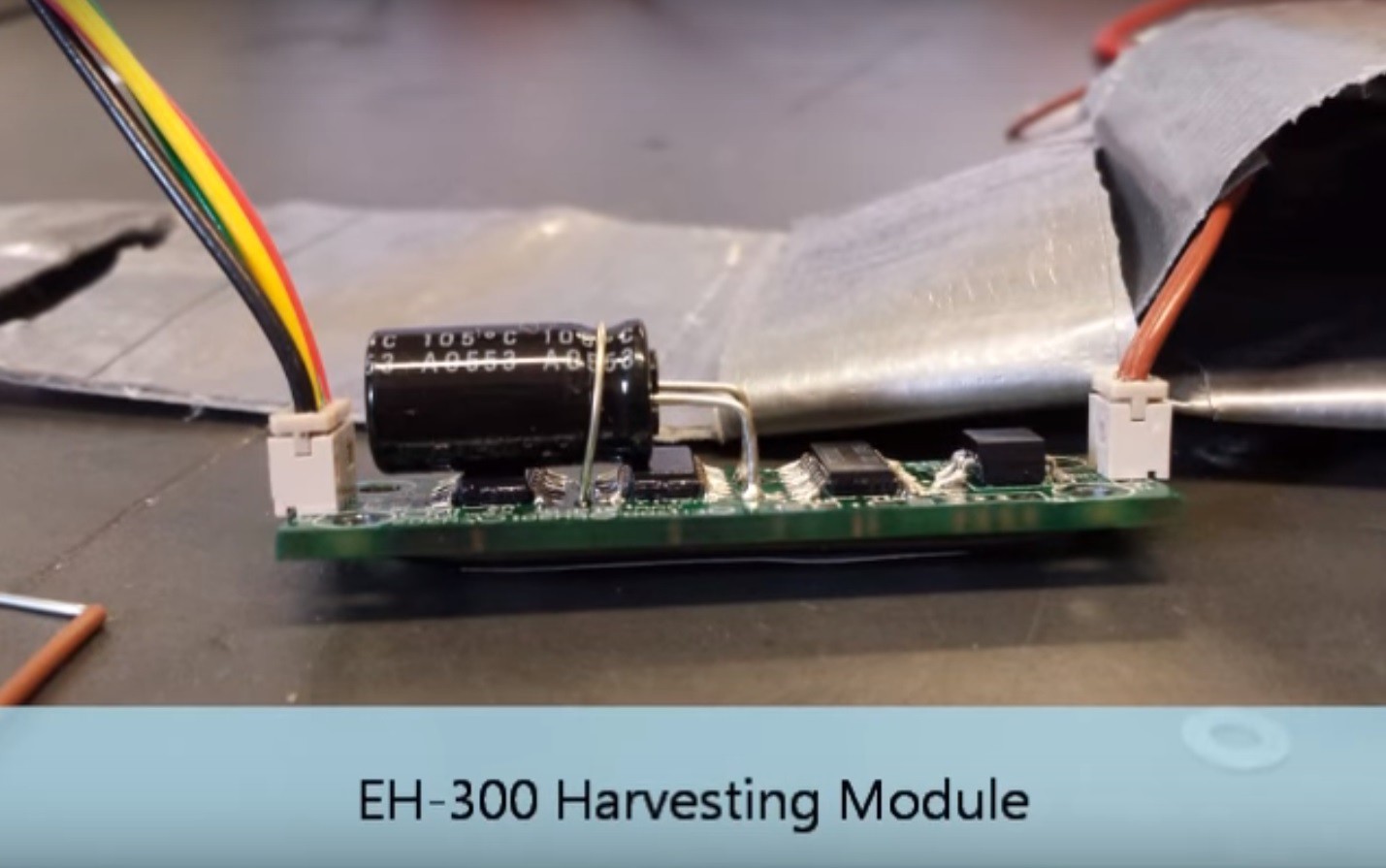
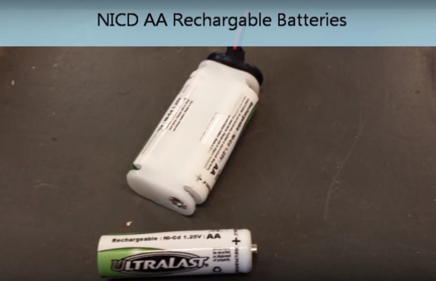
This phase is also simple. Tools that you need can be use from phase 1. For parts needed 2 elastic piezoelectric beam , NICD AA Rechargeable Batteries and EH_300 harvesting module. EH-300 is used to convert the energy from peizo to energy the battery can handle.
Here is the link where you can purchase elastic piezoelectric
http://www.piezo.com/prodproto4EHkit.html
Circuit Testing
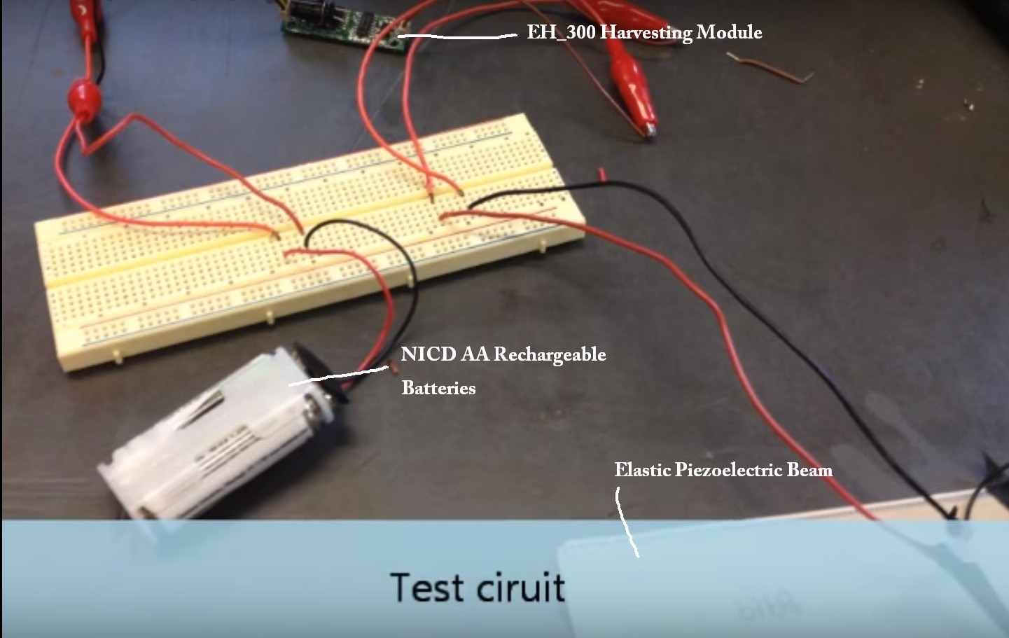
Before we fix all components in shoes first should test all components and also the whole circuit is working properly. With volt meter we can test the output of piezoelectric with bending. Also and check the final output from EH_300 harvesting module that will recharge our battery.
Fixing and ready to go
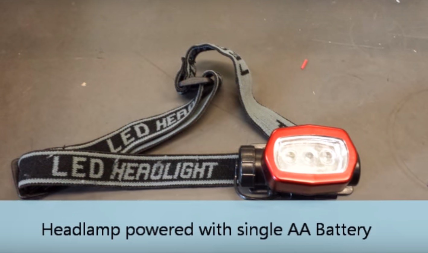
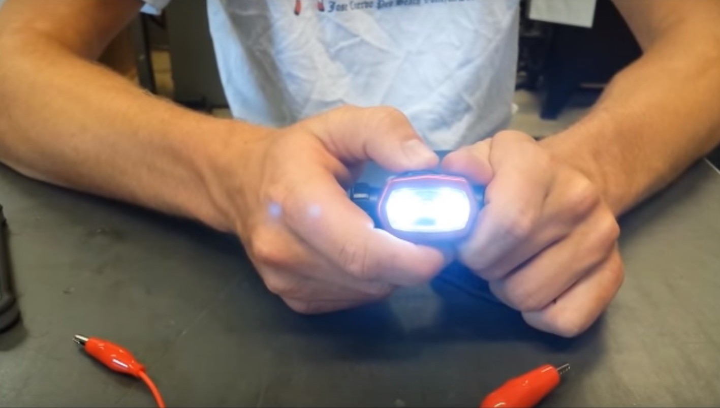
After checking the whole circuit we will fix all items in the shoes. Now our shoes are ready to recharge battery. After charging the AA battery we will test it on headlamp.
Future Scope
Future scope of our project is extremely good. It can be applied in any place where ever there is mechanical stress is in the picture. Few examples are as shown
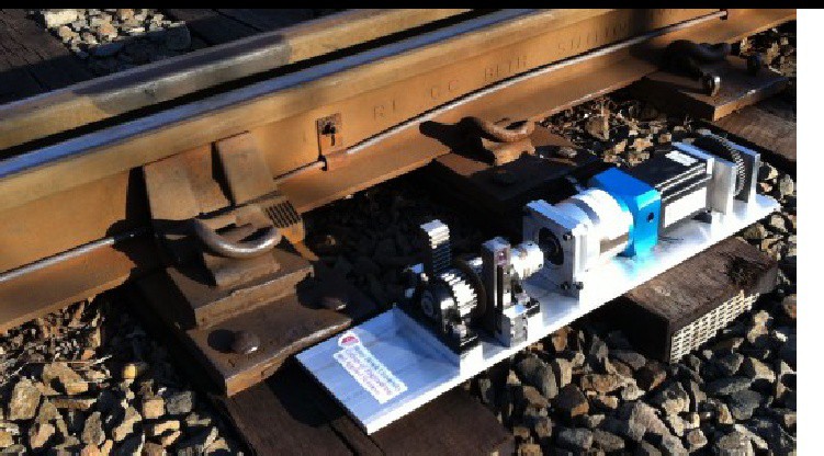
This piezoelectric system can be employed under the railway tracks so as when the train passes over it, it will lead to the generation electric power. The power generated by this system will be very large as the force applied by the trains would be very high.
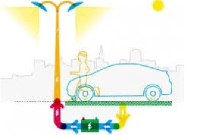
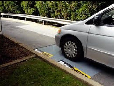
This system can be applied under the roads so when the cars pass over the road it will lead to the generation of electrical power. This power can be then used to power street light.

This system can very efficiently be used in wireless keyboards. Such keyboards then can be self-charging which will eliminate the frequent charging requirement of such keyboards
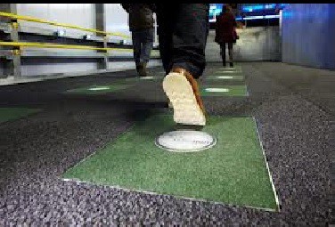
Also this system can be employed under walkway, so whenever people walk on the way it will lead to the generation of power