 Wasim Sahu
Introduction
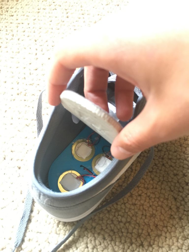
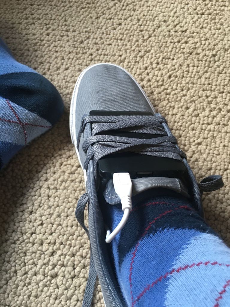
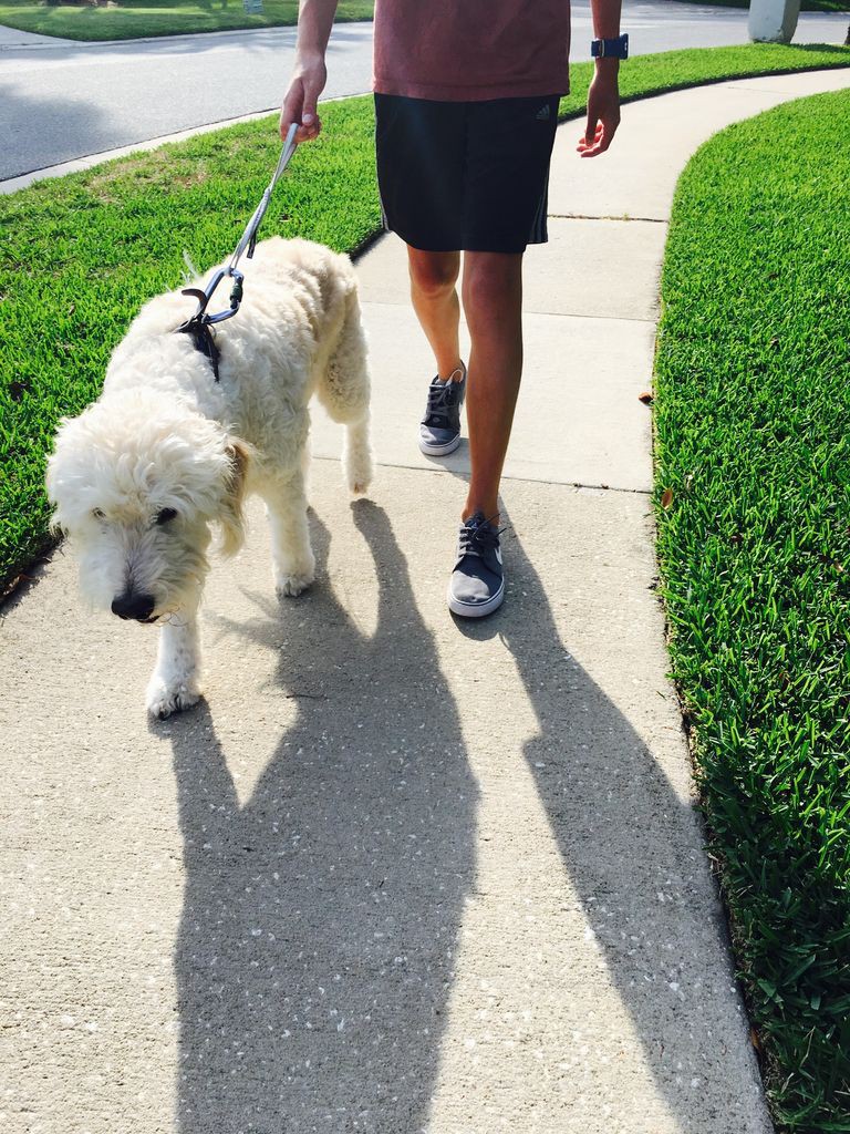
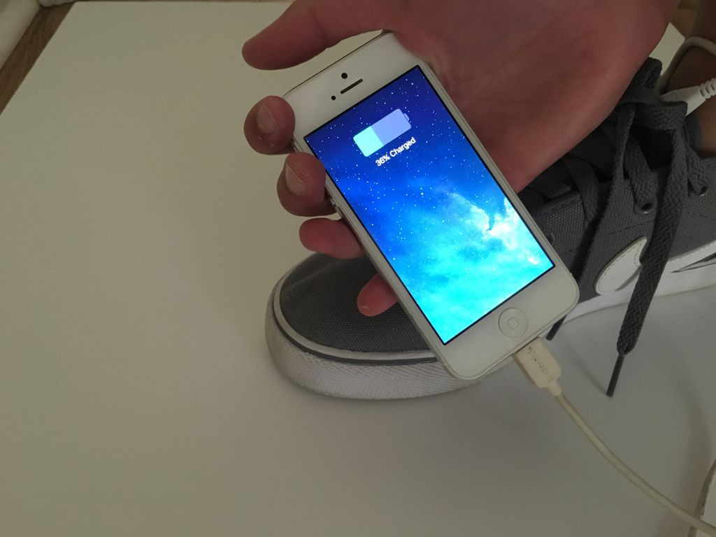
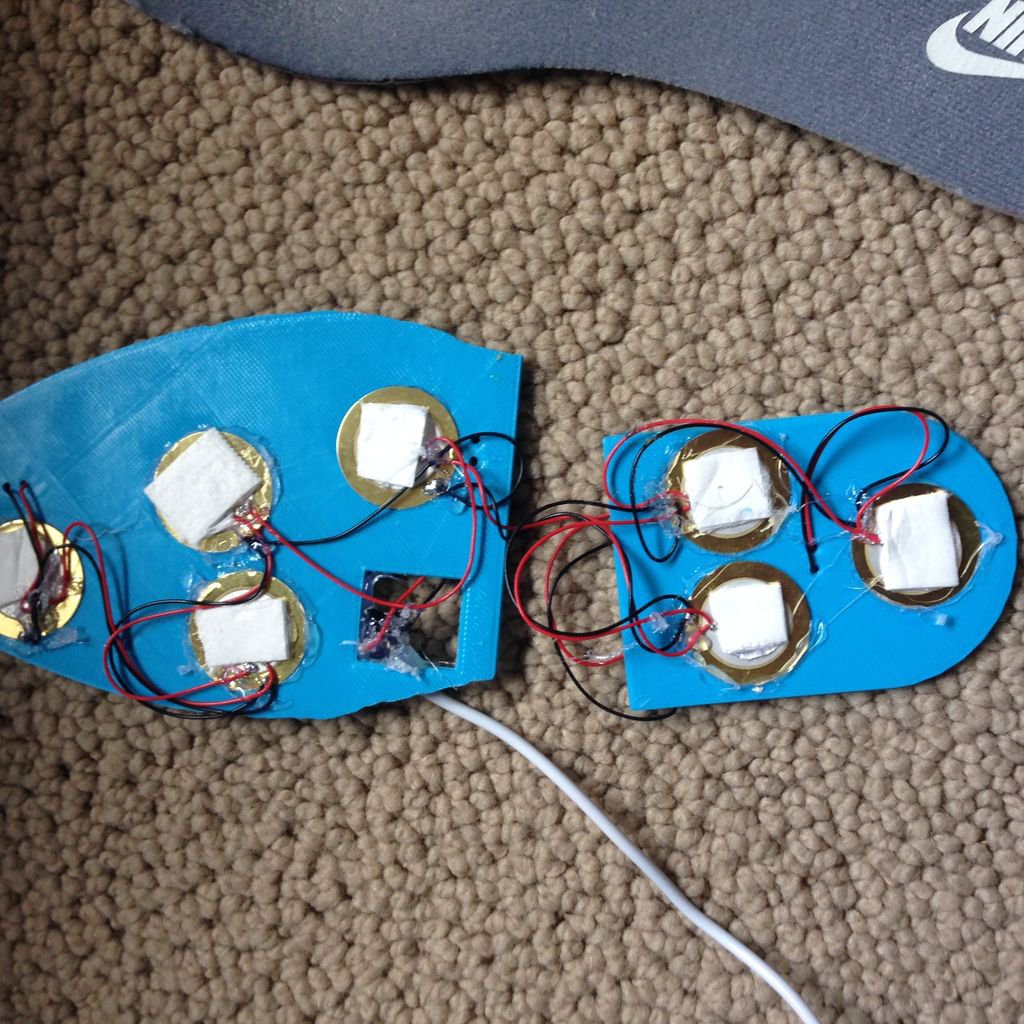
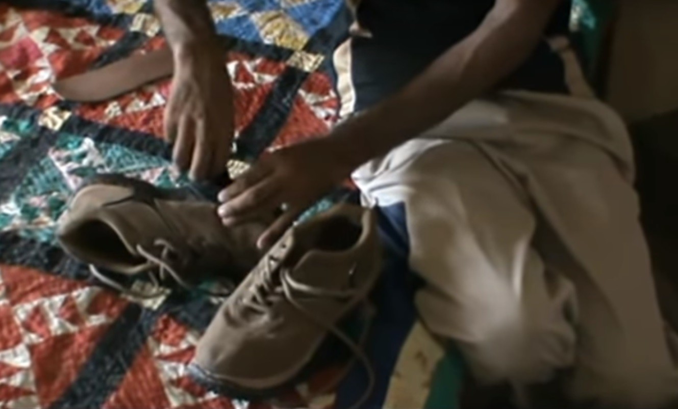
Hi dear hackday I hope you will be fine today. I am presenting a project about power generation with the movement of steps. It has 3 phases. First will be with piezoelectric, second will be with hand harvesting flash light that has dc gear motor and third will be a advance with elastic piezoelectric. I use the 3 phases to suite you. Which level of hardware you have. Basic normal and advance. Have you ever had that moment when you had a very important text to send, but before you could finish sending it, your phone died? Pretty much any person with a mobile phone/device has experienced that frustrating moment when a device fails to complete its task due to a lack of energy. My project is designed to fix this problem in a way that promotes health by creating a shoe insole that converts the physical energy created by walking into electricity, which is then stored in a portable battery pack. This way, you will always have an emergency power source (and you will be renewing some of your own physical energy too)
Aim of the Project
The aim of our project is to build a system that can generate power from that energy and use it. My project is extremely simple but highly useful. This system when applied on large scale can generate very high amount of power this power then can be used for upliftment of the civilization.
Phase 1
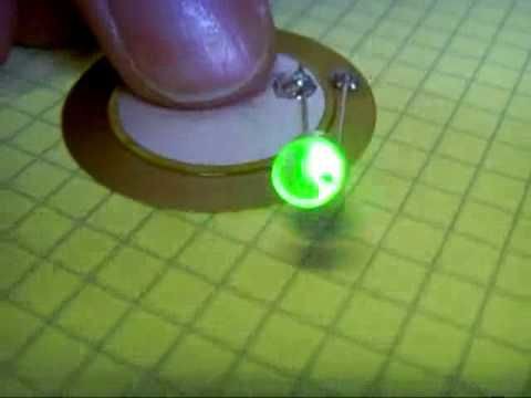
Energy Harvesting using Piezoelectric Materials
Parul Dhinga from dept. of E.C.E of M.I.T Manipal has explained theoretical model for energy harvesting system using piezoelectric materials have been presented. It is evident that harnessing energy through piezoelectric materials provider a cleaner way of powering lighting systems and other equipment. It is a new approach to lead the world into implementing greener technologies that are aimed at protecting the environment. Piezoelectric energy harvesting systems are a onetime installment and they require very less maintenance, making them cost efficient. One of the limitations of this technology is that its implementation is not feasible in sparsely populated areas as the foot traffic is very low in such areas. Further experimentation has to be carried out for its implementation on a larger scale.
PARTS AND TOOLS

The following lists are divided into 2 categories. The first category consists of things you NEED to complete the project, while the other list consists of things that are very HELPFUL.
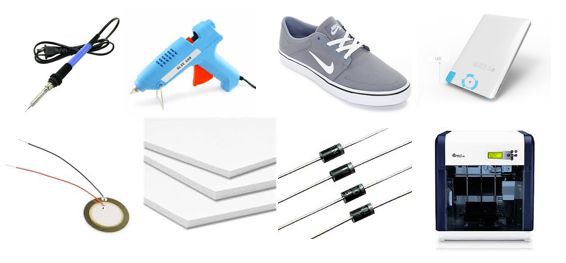
Things that you NEED:
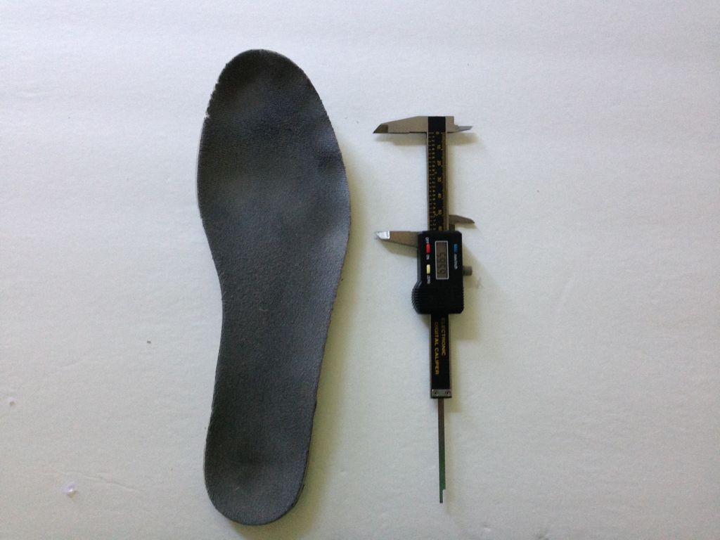
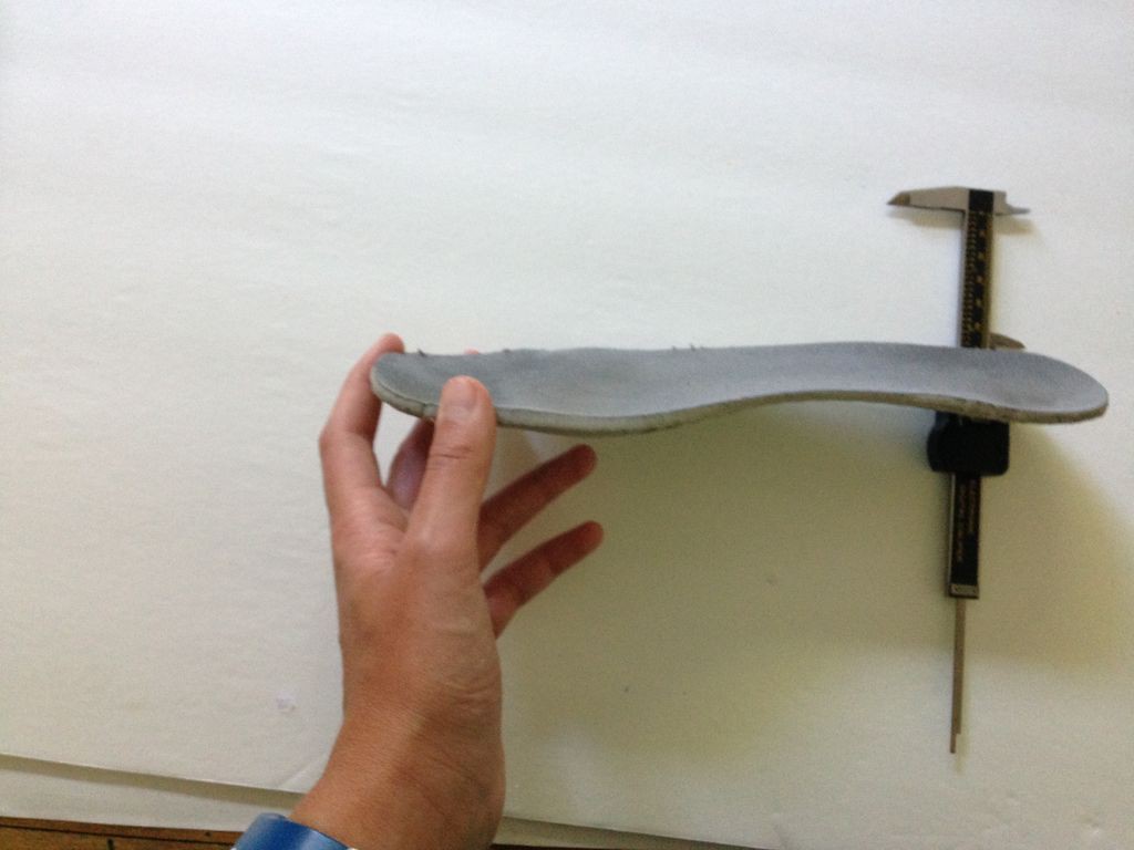
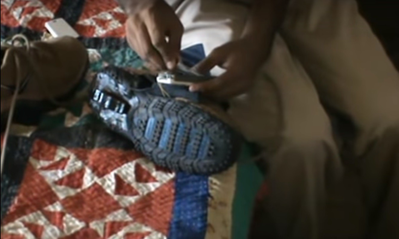
- Shoes (duh!)
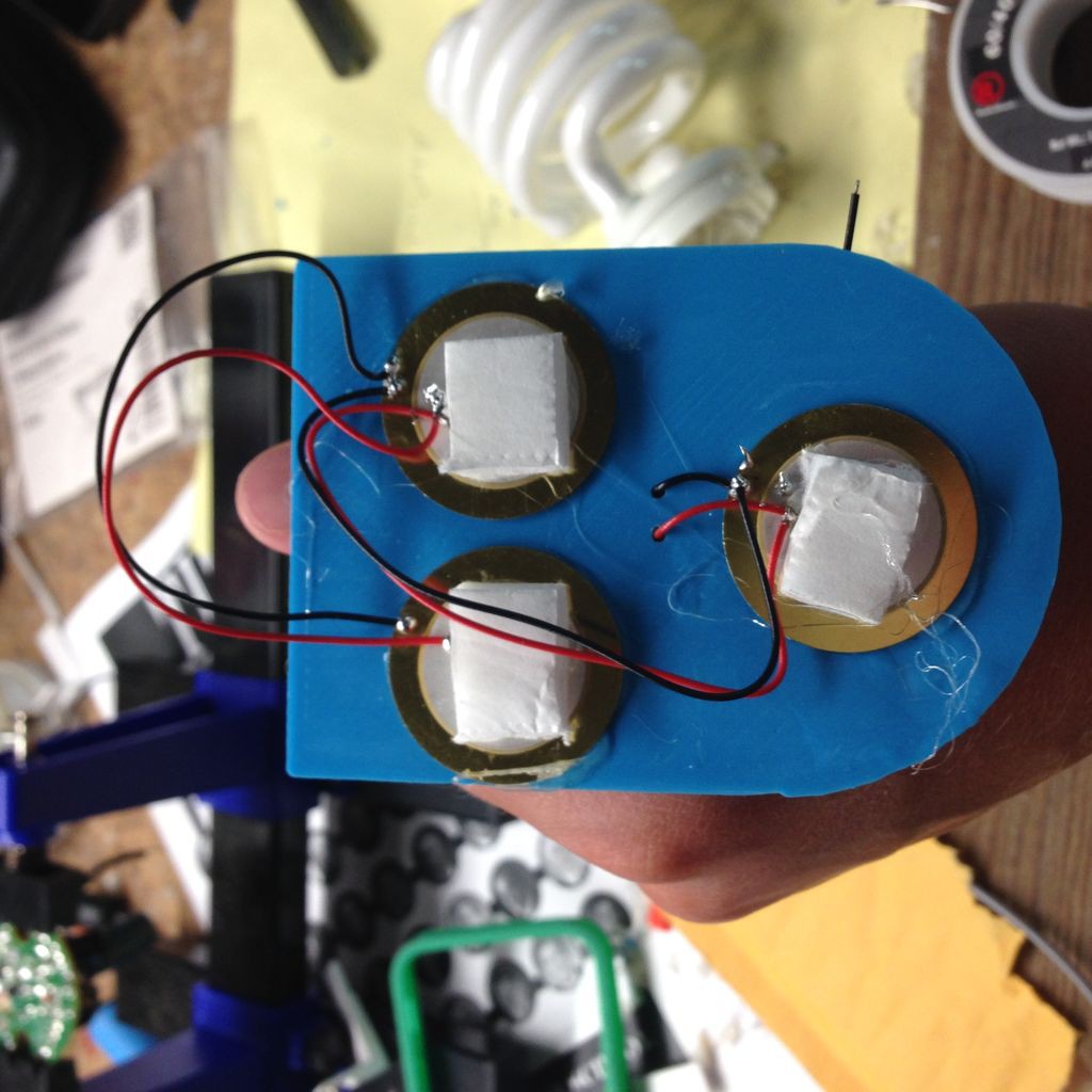
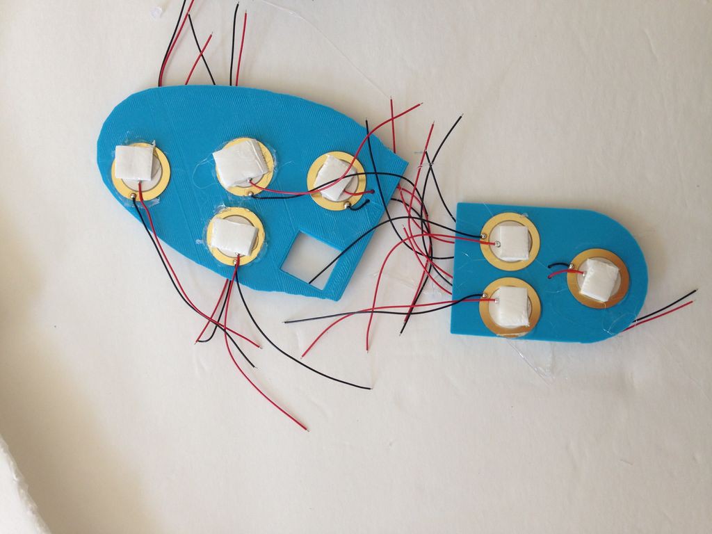
- Piezo electric elements (x14) I found 15 of them for 15.99
- Rechargeable battery pack w/ charger(x1) I got mine from 5 and Below for 5$
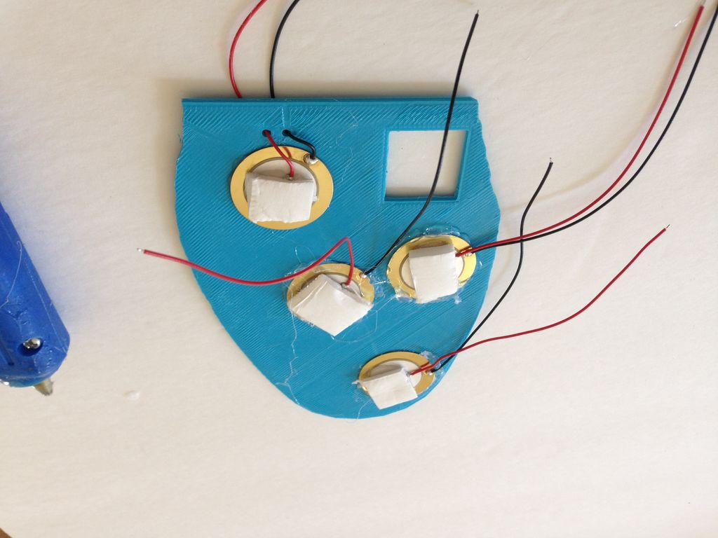
- Hot glue gun w/ hot glue
- Soldering iron + solder
- Foam/cardboard/anything you can squish (I used foam board that I got for 1$)
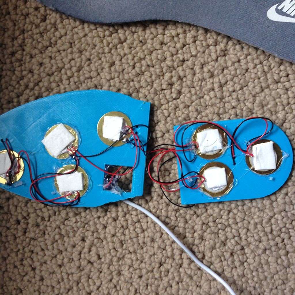
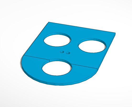
- Access to a 3D printer (If you do not have access to a 3D printer, you can always substitute a different material/plastic, but my instructions will be based off the 3D printed design
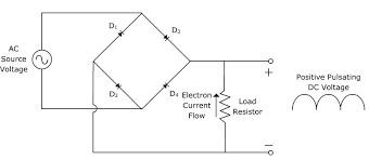
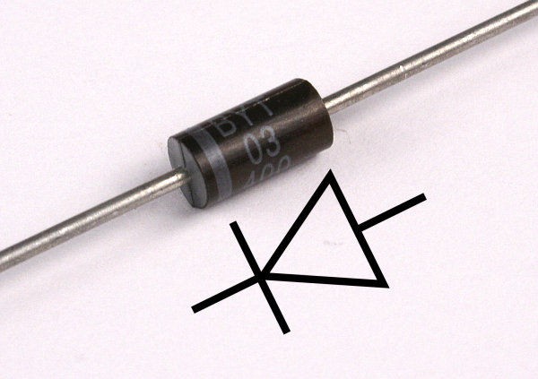
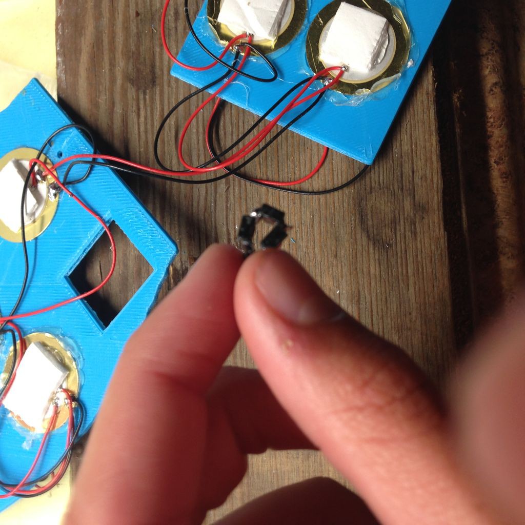
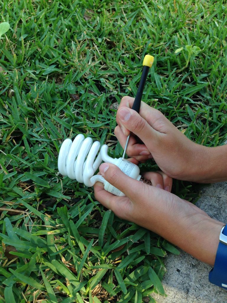
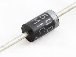
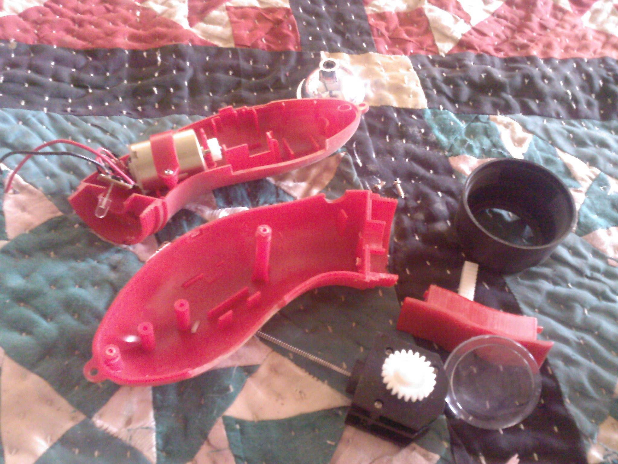
- 1n4001 - 1N4007 Diodes (x4) OR a CFL lightbulb, which I will show you how to take apart in order to salvage diodes needed for this project.
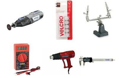
Things those are helpful:
- Dremel tool
- Helping hands
- Velcro strips (HIGHLY RECOMMENDED!)
- Multimeter
- heat gun (if taking apart CFL bulb)
- ruler/caliper
HOW DOES IT WORK?!


 Dimitar
 alnwlsn
 Aaron Swartz Day
 adriancubas
I know how to difficult to choose best shoes for boxing specially if we want online. Now, to day I am here to showing to my best reviewd headgear site which is helping ti you for choosing best shoes on cheap price.