0%
0%
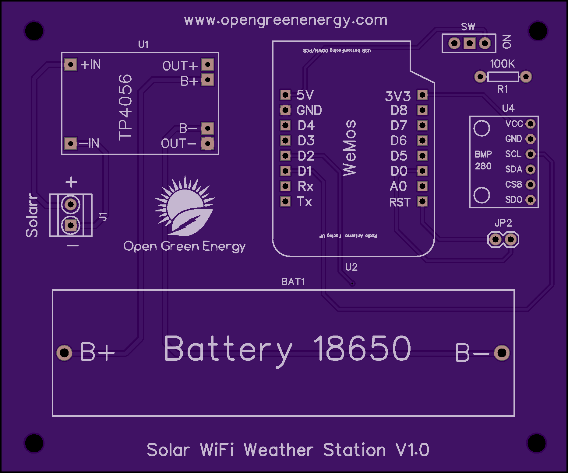
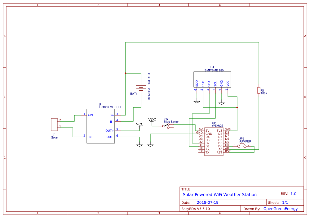
SOLAR POWERED WIFI WEATHER STATION
ESP8266 based Solar Powered wireless Weather Station
 Open Green Energy
Become a Hackaday.io member
Already have an account? Log in.
Just one more thing
To make the experience fit your profile, pick a username and tell us what interests you.
Pick an awesome username
hackaday.io/
Your profile's URL: hackaday.io/username. Max 25 alphanumeric characters.
Pick a few interests
Projects that share your interests
People that share your interests


 Ovidiu
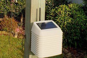

 facelessloser
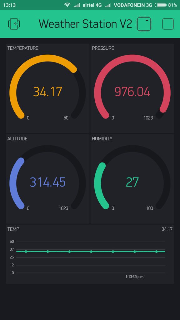
I need Fahrenheit for my Temperature readings.
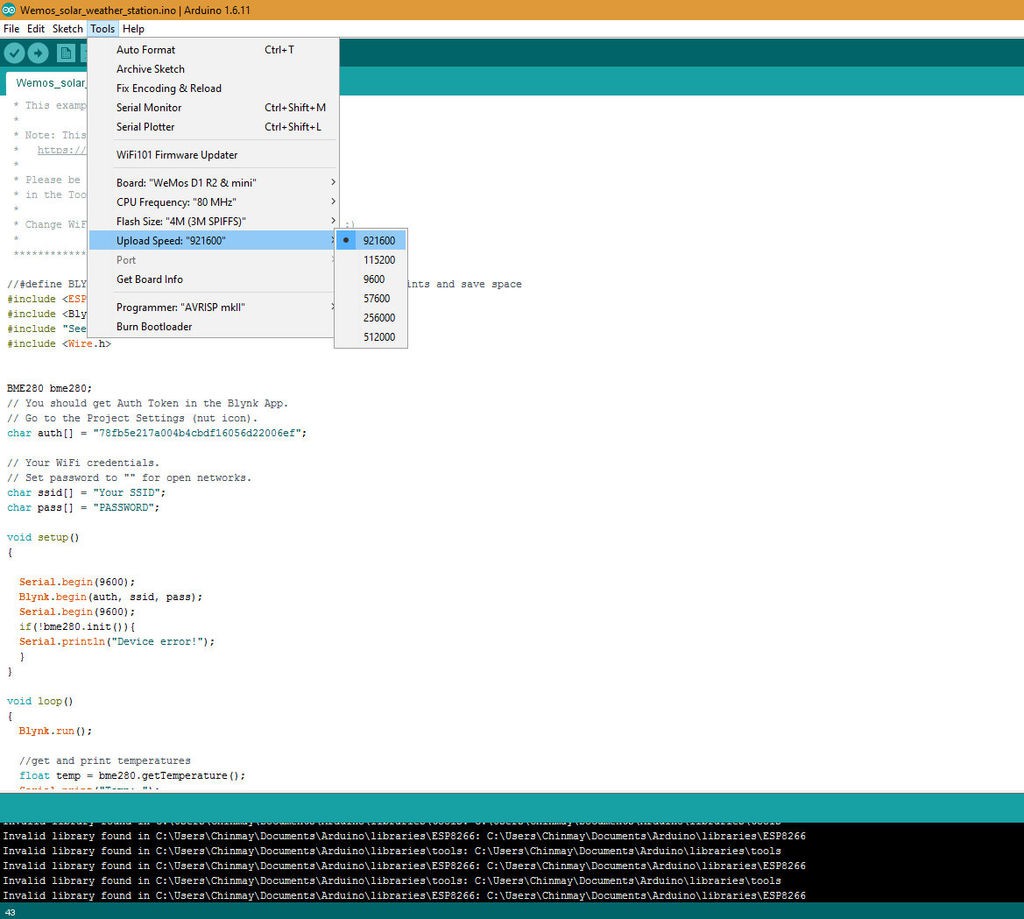
Do you see any issues with changing this line of code:
From:
measured_temp = measured_temp + TEMP_CORR;
And Changing To:
measured_temp = measured_temp *1.8+32;
It seems to be working. Let me know if you know of a better way to use Fahrenheit.
Thanks.