 Dan Julio
Introduction
The test platform hardware is pretty straightforward. I used an Arduino shield style breakout board to make it easy to connect the Teensy to the display and imaging module. Most connections between the Lepton module, LCD and Teensy are direct and documented in the image and included PDF schematic using the Arduino-style signal notation. The additional circuitry is for power management and control buttons. A LiPo charger/boost converter supplies 5V power to the various boards (the Teensy 3.3 volt regulator drives the 3.3v rail). It's controlled using a soft-power switch. The button initially enables power and then the Teensy drives D7 to hold power. D7 is released to shut power off. A few modifications are made to various boards.
Lepton Breakout Modification
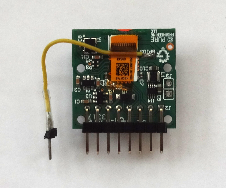
Pure Engineering provides a SMT pad on the back of their breakout for the Lepton's GPIO3 pin. This pin may be used to output a 105.3 Hz VSYNC signal that indicates the start of a segment transmission (a segment is 1/4 of a full frame of data and requires at least 60 164- or 244-byte SPI transfers). It is useful for synchronization. I use it as an interrupt on the Teensy to trigger a set of transfers. I brought the signal out to a pin plugged into the same header that the rest of the breakout board's pins connected to. I also removed the 2-pin power input (J3) that pokes out of the back of the breakout. A pair of 4.7 kohm pull-up resistors pulled to 3V3 is connected to the I2C signals.
Teensy 3.2 Modifications
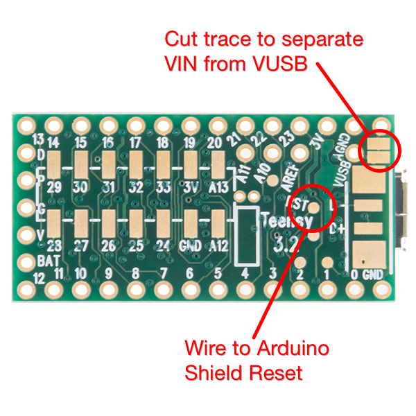
I cut the trace between VIN and VUSB on the back of the Teensy. I use VUSB as the input power to the charger and let the charger supply 5V that is fed back to the Teensy via its VIN to power it. That way the board may be charged via either the Teensy USB connector or the charger USB connector. The VUSB power line was connected to the spare Arduino expansion pin and routed to the front board containing the charger via the header. I also added a wire connected to the Teensy Reset pad on the bottom of the board and routed to the Arduino RST header pin. This allows the Reset button on the LCD shield to reset the Teensy.
Power Circuitry
The power circuitry is built around a now-obsolete Sparkfun PowerCell board. However I think one of their newer charger/boost converter boards (or something similar from another supplier) will work. The main requirements are an active-high boost converter enable signal and very low quiescent current when the boost converter is disabled (so-as not to discharge the battery). The system takes less than 250 mA at 5V. I removed the 10 kohm pullup R2 from the Sparkfun board to reduce quiescent current. The enable is held low by the resistor divider until the button is pressed enabling power. As soon as the Teensy starts executing code it drives D7 high which holds the enable high (the user has to hold the power button until D7 is high which is a few hundred mSec and indicated by the LCD clear screen). The resistor divider driving A6 is used to sense whether or not the button is being pressed. It does this by seeing the higher voltage when the button is pressed. The BAT54 diode is used to isolate the Teensy from Vbatt when the button is pressed. Different diodes may be used but they should be low Vf schottky units (the diode I used has about 0.3v Vf).
The battery voltage is sensed using another resistor divider feeding A7. To reduce power consumption when the system is off a n-channel MOSFET is used as a switch and to keep current from flowing into A7 when the system is off. Most of the n-channel MOSFET parameters are unimportant and a variety of devices may be used. The most important parameter is Vgs since the control signals are 3.3v based. Rds-on should also be fairly low, although with the resistors it may be even a few ohms if that's all you have in your parts drawer. A small - and non-critical - resistor holds the gate input low when power is removed.
Rocker/Navigation Button
The 3-way navigation button I used is also now obsolete. It can be moved right or left or depressed. My use is to scroll through items with the left/right movement and select between menus with the press. Any three individual or grouped buttons may be used. The firmware enables internal pull-ups in the Teensy.
Note about resistor values
The resistors used in the two voltage dividers where just units I had laying around. I was shooting for a 3R to R ratio so the voltage inputs on A6 and A7 would always be less than the Teensy's internal reference voltage of 1.2 volts. You can use a different combination as long as the voltage on A6 and A7 is less than 1.2 volts for a fully charged battery (~4.2 volts) and the series impedance is in the low 10k ohm range. A constant in the firmware represents the ratio and can be changed to match the selected resistors.
Note about wiring details
About the only critical wiring is the SPI lines. The firmware uses SPI clock rates up to 20 MHz so the wiring for these signals should be as short as possible.
Discussions
Become a Hackaday.io Member
Create an account to leave a comment. Already have an account? Log In.