 Dan Julio
The Beaglebone boards have an additional capability, aside from the PRUs, that differentiate them from many other SBCs like the Raspberry Pi. They have a true power-management controller (PMIC) that generates all the various on-board DC voltages and supports dual input voltage sources (DC in and USB in) as well as a 3.7v LiPo or Li-Ion battery including a charger. In addition the PMIC, a TI TPS65217 designed specifically for the AM355x processor, can be configured to supply power to the AM355x built-in real-time clock while the system is powered down and sports a power button that interacts with the kernel for controlled shut down - features that are perfect for a portable device like a thermal imaging camera.
Or at least in theory. It turns out that a hardware bug in the first revision AM335x processor and decisions about how to wire the PMIC to the processor in the original Beaglebone Black made it so the "RTC-only" mode would never work, and under certain circumstances could actually damage the processor (a current leakage path through the processor to the USB serial interface). However based on a lot of reading of various specs and errata I ascertained that the pocketbeagle shouldn't be at risk so I was excited to see how it ran on battery power (the battery signals are helpfully broken out).
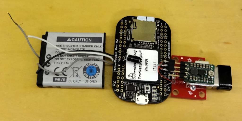
I connected an old camera battery to the pocketbeagle and added a 5V step-up boost converter to power a USB WiFi dongle attached to the pocketbeagle's host USB port. The PMIC wants a temperature sensor in the battery back and the camera battery had the right kind (10K). Unfortunately the PMIC doesn't generate a 5V out when running on the battery so the boost converter was necessary. I noticed that the 3.3V output was only powered when the pocketbeagle was turned on so it sources the boost converter. Success! Or at least I thought at first. The pocketbeagle ran happily from the battery with a reasonable current draw (< 200 mA w/ WiFi). And it charged the battery too when plugged in via the USB Micro-B interface - at least while the system was running. The problem came when the system was shut down. Charging stopped. This is hardly ideal for a portable device as not only do we expect them to charge while off but turning the system off makes more power available for battery charging.
The TI PMIC has the capability to charge the battery when its DC output supplies are disabled (system off) but clearly something was disabling that when the system was shut down. I dug into kernel source with help from a friend at my hackerspace and finally figured out the sequence of events that prevented charging when the system was shut down. It turns out that the device driver for the PMIC (tps65217.c) configures the PMIC to enter "off" state when powered down instead of "sleep" state which would let it charge the battery. A fuller explanation is documented in the pocketbeagle's google group.
I thought this was good news because the driver configures the PMIC during probe at boot time and the PMIC can be reconfigured via its I2C bus after the system boots. I tried it. Success again - kind of. The battery charged after the system shut down. But there was also a ~15 mA load on the battery from the switched-off system - enough of a load to discharge a battery pretty quickly if the system was disconnected from the charger. Unfortunately the pocketbeagle uses an Octavo system-in-a-package and I couldn't understand what could be causing the additional discharge. Fortunately Octavo replied to a question on their support forum. When the PMIC is configured to "sleep" mode enabling battery charging, it also enables one LDO regulator that is designed to feed the RTC input on the processor. Octavo also connected another power-rail (plus an enable to the 3.3V LDO) to that output per TI's spec and the quiescent current is huge, at least 15 mA huge. Octavo claims that a future version of the chip, one with an on-board EMMC, will not have the same connection and may work. But this device will not be on the pocketbeagle so my idea of using the PMIC to charge the battery was dashed.
Well, there is one work-around I thought of. I can add an external circuit or micro-controller to handle the on/off power button. It will toggle the pocketbeagle's power button input when the system is shut down but it only signal an application running on the pocketbeagle via a GPIO when the system is up and the user wants to turn power off. This would let the application shut down the thermal imaging app and display to reduce power consumption while still leaving Linux running until the battery is charged. Then the system can fully shut down via some additional handshaking between something running on the pocketbeagle and this additional circuitry. I still have to add an external RTC since I want the system to know the right time so it can timestamp pictures saved to non-volatile storage. Plus an external boost converter for USB (WiFi). It is a not-insignificant amount of additional circuitry.
In the end I decided I will re-use the design I did for a gadget called the Solar Pi Platter I designed to power the Raspberry Pi Zero from a battery. It provides power control, automatic power-path switching, battery charging, and a RTC as well as a (power-hungry) USB Hub. I am going to modify its firmware slightly to utilize the beaglebone's power-control input and sense when Linux has shut down before killing power turning the Pi Platter into a Beaglebone power solution.
Next up is to put together a prototype using the pocketbeagle, a hacked Pi Platter, battery, the Lepton, and a touch LCD. A change from last time, based on playing with the littlelvg graphics library, is a move back to a resistive touch panel controller. The littlevgl library has a on-screen keyboard that will be nice to use when entering WiFi credentials but it turned out to be really hard to use with the capacitive touch panel controller (tiny buttons, big fingers). I think it might actually be easier to use with a resistive panel and a plastic stylus. We'll see.
It's a shame the power subsystem on the beaglebone's isn't slightly more capable. While it will work as a UPS, it's going to be hard to make a battery powered gadget without going through extra hoops.
Discussions
Become a Hackaday.io Member
Create an account to leave a comment. Already have an account? Log In.
Adding this comment for future travellers. I have personally run wifi devices attached as shown on 3v3 from one of my pocket beagles. Inside the USB device is a buck converter that converts the 5V to 3v3. It turns out that if you simply supply 3v3 the device works just fine, and operates a bit cooler. However, if you are using a USB hub on the port, you will need that 5V.
Are you sure? yes | no
Hello Dan,
I was reading the datasheet of the Octavo system, TPS65217 and I couldn't understand the 15mA from the LDO that you said. The power-rail that they added is the TL5209 but on the Octavo datasheet they say that this LDO is enabled by the TPS65217 LDO4 [Octavo family datasheet rev.15, page 25]. So, in theory we could disable all LDO's that are not connected to the processor via i2C.
On TPS65217 they say that in sleep mode the LDO1 and LDO2 are limited to 1mA, and in sleep mode all LDO's are disabled with exception of LDO1 that is kept on the state as was in active state before sleep mode [page 40 of the datasheet, march 2018].
But even if all LDO's are on I don't see a 15 mA quiescent current in any of the components. Could you specify what component has this huge quiescent current?
So if the another LDO that Octave added to the package (TL5209) is controled by the LDO4, I would think that it would be off when we have a sleep mode on the TPS65217. Maybe we can verify it if we can measure if there is voltage on the 3V3 rail when we are on sleep mode. Also, have you tried to remove all components that you added to the board? wifi donlge, booster, and even the wires, and the capacitor that you added? keeping only the battery connected?
Best regards,
edit: I saw the explanation in the google group. From the new octavo datasheet they say that the 3v3 LDO that they added can be enabled by the LDO4. Do you think that if we want to switch off the system, keeping the TPS in sleep mode we could send a command to switch off LDO1? Or it would switch off the processor all together? Could we send this information in a safe time? I wonder if we send LDO1 to off, and after, when we want the system to boot it would boot... Probably we would need to reset the TPS (PB_IN low for 8 seconds) which seems to enable all the LDO's. I don't know if this is the same pin that we have on the reset button.
Are you sure? yes | no