 Nicolò
As you have seen I had a huge problem with the SIM800 module. But the design of the basebord looks roock solid. Even if I have made a few mistakes.
Thi is my first experience with mosfets, I never used before. (At school I only used opamps. Discrete semiconductors weren't on my school program)
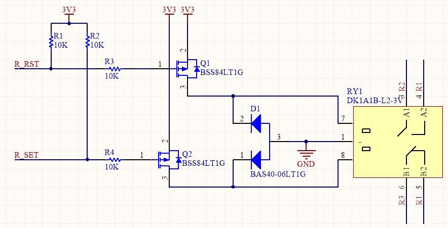
I have spendt fiew time online looking at how a mosfet works, how to choose it. Due to the relay coil configuration I had to choose a P-Channel mosfet (BSS84L).
I was expecting something wrong, really wrong. I used a couple of times standard BJTs (using already made schematics) as on off switch but nothing more. I have soldered all the parts. I also mixed the diode and the mosfet trains so I had to rework my board.
With the multimeter in my hand I measured the continuity, I checked for shorts and I have found one with the reset chip of the ATmega. At that time I tried to see if it was due to my 0-level skill on SMD soldering.
I tried to apply power to the board, just to see if the magic smoke would come out: nothing.
I then started the search process of that short-circuit the pullup was looking fine, so I decided to remove the microprocessor (There was nothing ele on that line). The short was gone! I may have fried the chip with a too high temperature. I than lowered it and soldered a new one. After that the reset line was HI so I was able to program the IC.
I have soldered the ISP wires on the programming pads (I'm still working on the programming clamp) and using an Arduino Mega I burned the bootloader to the IC, I uploaded via serial the classic blink example.
I have no LED on pin 13 so I simply hooked the multimeter on the pin. It was working!
Sorry I don't have any photo of this stage :(
The bootloader was working the microcontroller was running a sketch. The next step was to test out the relay part. I wrote a couple of lines inside a loop to toggle on and off the relay.
This is a bit more complicated than usual. This is a dual coil latching relay so I seed to generate two pulses to toggle the state.
I wrote the following code:
// the loop function runs over and over again forever
void loop() {
  pulse_relay_pin(RLY_SET_PIN);
  delay(5000);                       // wait for a second
  pulse_relay_pin(RLY_RST_PIN);
  delay(5000);                       // wait for a second
}

void pulse_relay_pin(byte pin) {
  digitalWrite(pin, HIGH);
  delay(100); // wait
  digitalWrite(pin, LOW);
}
The relay was toggling, but it was making an odd sound. Initially i was more concernd about the protection diode so I hooked up my DSO to see the voltage spikes. I then realized why the relay was making that odd sound. Have you spotted the error on my previous code?
I'm pulsing HIGH but the mosfet are P-type so they are "active LOW" (Yes I know that is not so simple), I figured this out becaouse the voltage across the diode was always 3.3V.
After correcting the code all was working fine:
void setup() {
  pinMode(RLY_RST_PIN, OUTPUT);
  pinMode(RLY_SET_PIN, OUTPUT);

  digitalWrite(RLY_RST_PIN, HIGH);
  digitalWrite(RLY_SET_PIN, HIGH);
}

void loop() {
// Same as before
}

void pulse_relay_pin(byte pin) {
  digitalWrite(pin, LOW);
  delay(100); // wait
  digitalWrite(pin, HIGH);
}
I left the board running for half a day while I was tring to troubleshooting the SIM800 and after all that time it was still working. Not a complete durability test but at least I have some hope.
I'm still waiting for the PSU, but i'm running the board with 5V via the on board regulator. Looks fine, it is cold under the load of the relay and the uC.

Discussions
Become a Hackaday.io Member
Create an account to leave a comment. Already have an account? Log In.