 Jan Waclawek
The key issue in maintaining RTC operation during "no power period" (night in case of using solar power) is storage of sufficient amount of energy. We excluded parts based substantially on chemical processes (accumulators, supercaps, electrolytics) because of their inherent lifetime limitations, and ceramic capacitors on grounds of their relatively high leakage, preventing them to keep charge beyond a hour or so. So what we're left with is the finest kind of foil capacitors, namely the polypropylene ones, which exhibit the lowest leakage of all commercially available capacitors.
However, PP capacitors are expensive per microfarad, and they are bulky, too. From the charge equation:
assuming that a CMOS RTC will work in a cca 2V-3V supply power span (i.e. a 1V voltage drop), the required time from dusk to dawn is around 10 hours i.e. 36ks, and the current consumption is 40nA, and applying a snippet of optimism (i.e. that there are no other significant leakages) the required capacitance is around 1.5mF. In commercially available PP foil capacitors, available in capacitances up to few tens of uF, that converts to hundreds of euros/dollars, which - even taking into account that we might spend somewhat more on a clock which will never need batteries, maintenance, nor replacement - is more than we might be willing to spend. That the sheer volume of such capacitor battery may be larger than we would like to allocate for a clock, is another (albeit slightly less important) negative factor.
So is there any hope we might ever accomplish our task?
It's time to start to think a bit out of the box.
What is the reason why foil capacitors are bulky and expensive, compared to other types of capacitors? Price is given by the amount of material used times the cost of material, plus the cost of time/labour spent on preparing them. As the first factor is of the same reason as the "bulkyness", let's have a look at it first. Given similar thickness of the needed metallic contact layers, capacitance-to-volume ratio is given by the basic properties of capacitors: permittivity of the dielectric layer, its thickness versus breakdown voltage, and its area. Electrolytics and tantallum are unbeatable in volumetric efficiency because of they employ a "trick" to increase the latter two to its extremes: dielectric area is increased several orders of magnitude above the basic area of electrodes by creating a "spongy" structure using various methods, and the dielectric is "grown" electrochemically to exactly the minimum thickness needed for a given breakdown voltage. That the bulk of capacity of elyts/Ta is given basically by "growing" also decreases manufacturing cost per microfarad. High capacitance ceramic capacitors employ a high permittivity material, sandwiched with metal foils to a multilayer structure in huge sheets, which is then cut up into thousands of individual parts, so there is significant parallelism in making them (and, given the huge demand for them, they are manufactured in highly automated way which drives down the manufacturing costs too). Foil capacitors can do neither of these: the plastics have a relatively low permittivity, they are based on thin plastic foil and their breakdown voltage is given by the thickness of the foil so it has to be perfectly smooth and flat and any "sponginess" is excluded. Then they are metallized, wound up and packaged, and while there may be some amount of parallelism and automation applied, it's way lower than at the other types of capacitors.
So in capacitance the foil types simply can't beat other types. Do they have some other distinguishing feature then, which could be utilized?
The fact is, that foil capacitors are good at insulation voltages. So good, that PP capacitors rarely have rated voltage below 100V. Can't we utilize this fact?
So far, we asumed, that in the RTC "emergency supply" line there is no active electronics, just the capacitor, charged through a switch (diode) from the primary power supply. So let's give up this simplistic view and let's assume we can use a capacitor charged to tens of volts. We would need a step-up on the charging side first, but as we assume there's relatively plenty of energy on that side, that's then a comparatively simple task. What is going to be a challenge is a stepdown "voltage regulator" on the RTC side, and one with quite unusual requirements:
- high voltage input (tens of V, if possible, up to 100V)
- low voltage output (2V-3V)
- low current (up to 1uA)
- extremely low self-consumption (sometimes called quiescent current, but sometimes this name confusingly denotes a different parameter - consumption while the regulator is off/disabled)
- high permissible output ripple (2V-3V output, ie. 1V ripple, is quite okay)
It's very unlikely there is any commercial offering with these parameters. Usually it is assumed, that high voltage input implies an off-grid or similar primary source, i.e. that once there's voltage, there's power. Also, high-voltage electronics is exceedingly rare these days, and searching for "high voltage input" often returns parts rated with input voltages only slightly higher than 5V... When it comes to rare and exotics, Linear (having been gulped by Analog) and Maxim come into mind, but the best I could find was LTC3255, but that works out of that premise above and has near zero efficiency at the higher voltages input...
The primary idea towards the required stepdown is to use a charge pump, decreasing voltage by transferring small amounts of charge using a relatively small transfer ("bucket") capacitor, into a much larger output capacitor. The ratio of capacitances should be set so, that one "bucketful" of charge from the fully charged input capacitor (i.e. 100V) should not increase the output voltage by not more than the maximum ripple, i.e. 1V - that gives us straighforwardly a 1:100 "bucket":"holding" capacitance ratio.
The following simulation illustrates the idea:
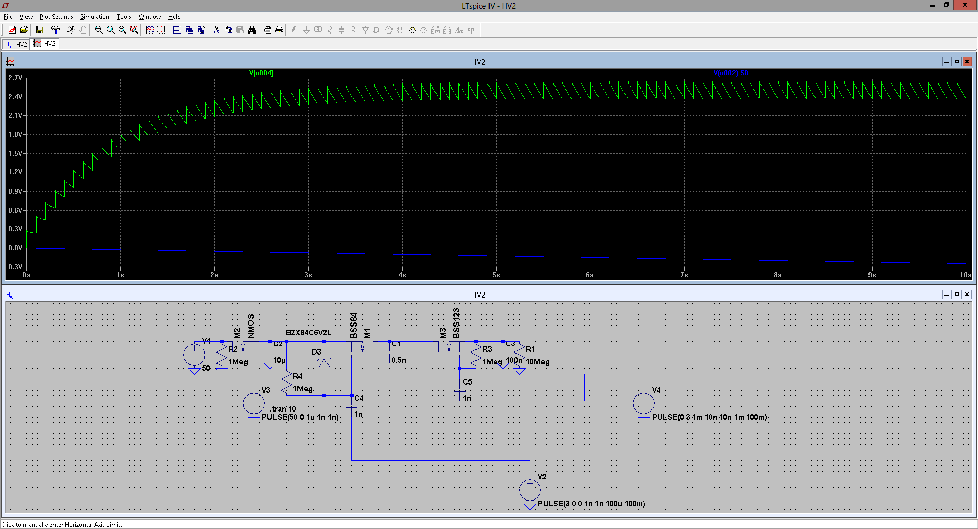
Green line is voltage on the "holding" capacitor (thus the target RTC power supply), blue line illustrates decrease of the "storage" capacitor voltage.
V1/R2/M2/V2 on the left simulate the input "stepup" - here only charging momentarily the main "storage" capacitor C2 to 50V. C1 is the "bucket", R4/D3/M1 represent the "high switch" and R3/M3 the "low switch". C3 is the "holding" capacitor and R1 represents the load - here, some 200-300nA, as the simulation was inteded towards using not the "optimal" RTC, but the RTC incorporated in STM32L476.
Note, that both the "bucket" and "holding" capacitors' leakage contribute to the total current, so they have to be of the extremely-low-leakage type (i.e. PP foil), too.
C4 and C5 (together with the "bleeding" 1M resistors R4/R3) are primitive level shifts for the MOSFETs, driven by the "control electronics", represented here by voltage pulse sources V2 and V4. As for a homemade project it's unlikely I will be able to get manufactured my own low-leakage CMOS control IO, the plan is for prototype to use the STM32L476 in its lowest-consumption mode, being periodically woken up by the RTC so its generates the needed pump-pulses on two of its inputs and then goes to sleep again. This would increase its consumption to roughly twice as much, but it still would be viable for a proof-of-concept.
To reduce self-consumption further, the idea is to omit "immediate" feedback. Feedback involves a voltage divider, a comparator and a source of reference voltage, all these being hungry for power we don't have. OTOH, we settled for higher ripple, so the idea is, that the charge pump would run most of the time in a "purely digital" manner, using calculation to estimate the remaining voltage on the "storage" capacitor, and from that - as the "bucketful" of charge decreases with decreasing input voltage - the needed time between "pump-pulses". To avoid problems with unknown tolerances of used parts, the calculation may be calibrated against measurement beforehand, while there is enough input power - the mcu comes handy here.There may be an occasional feedback, with dividers well-isolated by low-leakage MOSFETs, switched on only rarely and only for the absolutely necessary time of measurement - both during calibration and "runtime".
This whole arrangement is apparently complex, employing nontrivial electronics plus software, and obviously ridden with a large number of potential pitfalls.
So, may there be any other, simpler way?
Discussions
Become a Hackaday.io Member
Create an account to leave a comment. Already have an account? Log In.