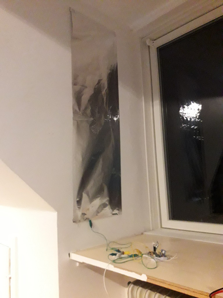
Let's say you are making a low power device, for example a nice sensor node for your smart home, and you don't want to use batteries. You want to use some ambient power source, for example indoor solar cells or ambient RF. The challenge is working with extremely low levels of power available in residential homes. For example on walls of a living rooms or in bedroom there is about 10-30lux or even lower illuminance. A cheap AM-1417 solar cell would produce around 500nA at 2V under these conditions meaning there isn't a lot of current to go around.
Therefore we need to collect those nanowatts into a storage capacitor, charge it to a threshold level and then activate the load once there is sufficient energy to run it. The minimum amount of power we can collect is going to be driven by the consumption of the circuit performing the monitoring of the storage capacitor.
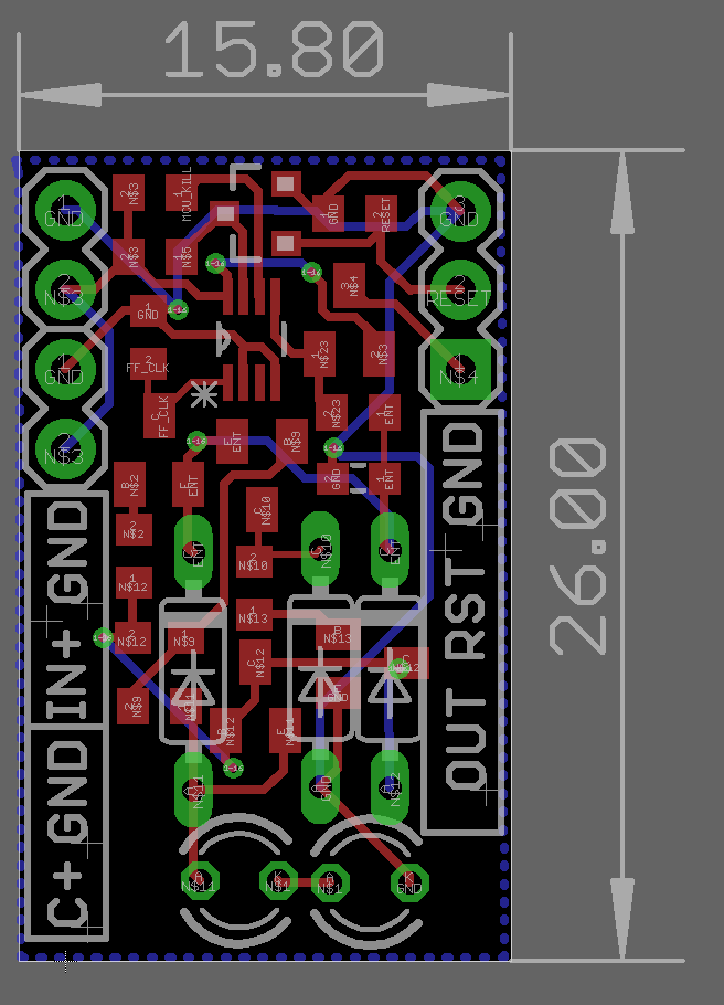
This project is demonstrating a power management module that can be used to interface a very high impedance source, collect those precious nanowatts and then power the load. The circuit monitors the voltage of the storage and when the threshold voltage is reached it activates the load. But wait, there is more! Once the threshold is reached, and the load is connected, this circuit will disable the voltage monitoring part allowing even lower system consumption. This is especially important in two scenarios: first, if the load has a low power mode that has lower power consumption than the monitoring circuit thus making it better to keep the load connected instead of the voltage monitor. Second, if the voltage monitor has a very high current consumption after it has detected the voltage level.
The circuit has a voltage monitor reset input that will disable the output and restart the process of voltage monitoring if the load should be disconnected once its task is done.
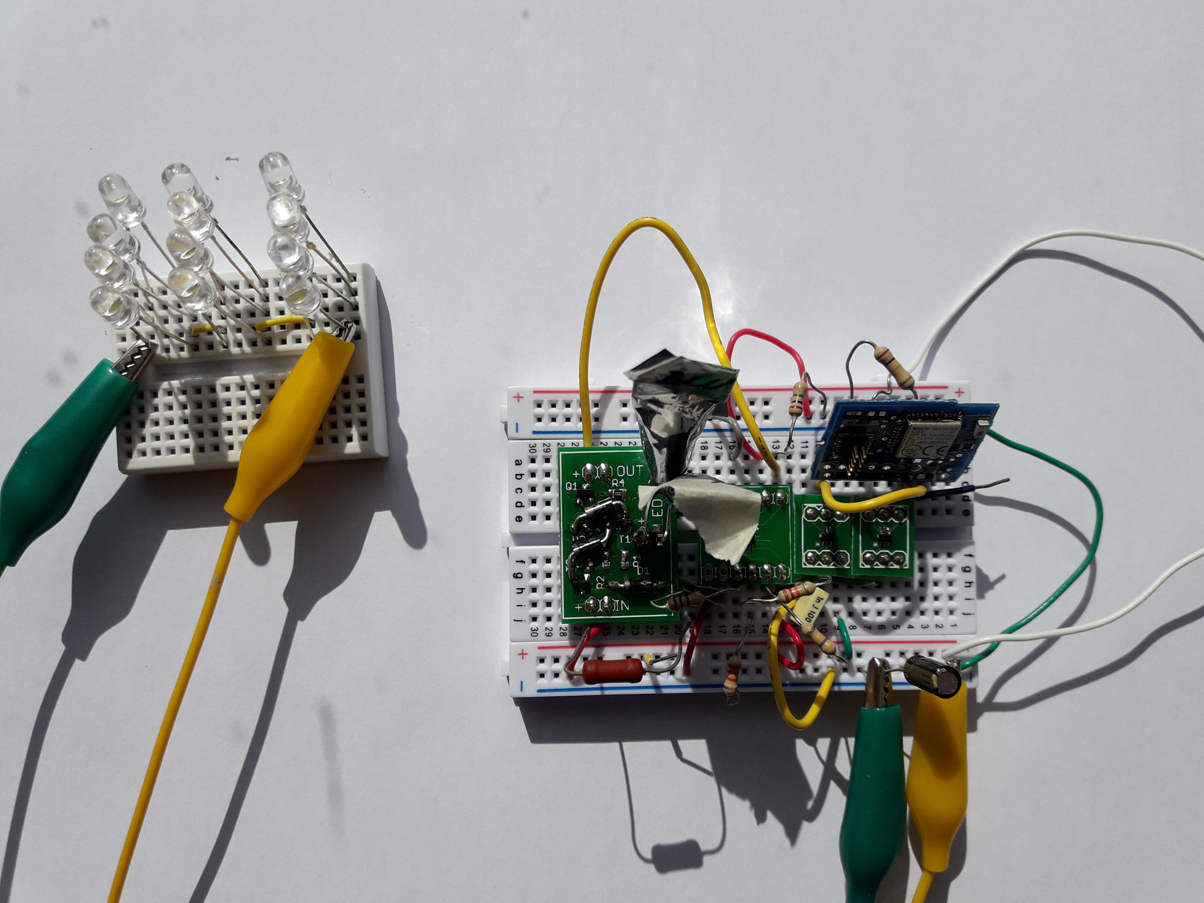
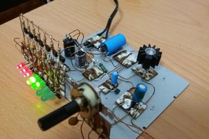
The heart of the system is the voltage monitor. The power consumption while initially charging is going to depend on the choice of the voltage detector circuit. The lowest power consumption I have achieved is using this circuit as a voltage detector. Its interesting how this voltage detector circuit is based on standard BJTs and that it uses LEDs as a reference for voltage detection. However, there is one big drawback. Once the voltage on the input reaches the voltage threshold the circuit's current consumption spikes to several mA which will drain a small input capacitor in a blink of an eye. Therefore, the rest of power manager is there to use the voltage detector as a trigger and then disconnect it, thus preventing the massive energy loss. Furthermore, the voltage detector circuit on its own would discharge the input capacitor until it reaches 0.6V which is a waste as most electronics stop operating a bit below 1.8V.
As LEDs are used for voltage reference the selection of threshold voltage levels is limited and the threshold value is going to be dependent on the environmental conditions. If a precise voltage control is required another type of voltage detector can be used. For example a Torex semiconductor XC6135, XC6136 or an Intersil ISL880xx series of voltage detector circuits.
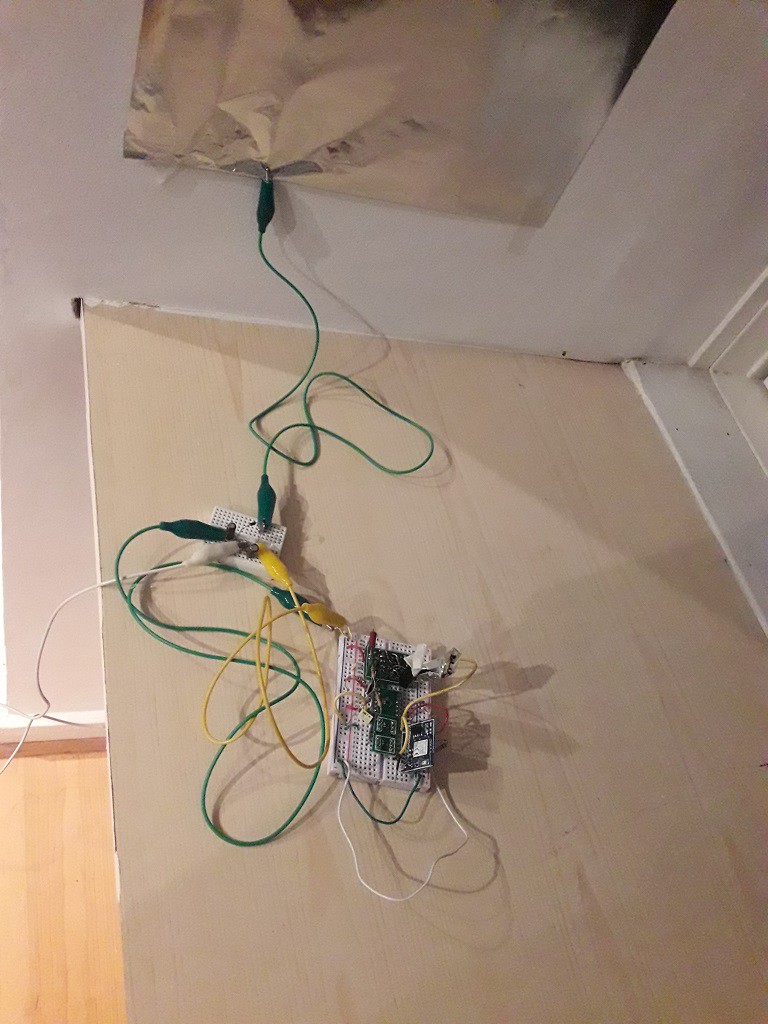
In the examples shown in the project log it can be seen how the high input impedance of the circuit comes into play when using low power sources such as solar cells indoors, ambient RF or even using LEDs. I have successfully powered a Bluetooth low energy sensor that measures temperature using some of the previously mentioned power sources.
 Hasan Murod
 Mario Ninic
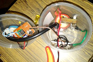
 Discrete Electronics Guy