0%
0%
SmoothMove - A New Human Computer Interface
Small, Ergonomic, Portable and better than any other travel mouse
 Chris
ChrisBecome a Hackaday.io member
Already have an account? Log in.
Just one more thing
To make the experience fit your profile, pick a username and tell us what interests you.
Pick an awesome username
hackaday.io/
Your profile's URL: hackaday.io/username. Max 25 alphanumeric characters.
Pick a few interests
Projects that share your interests
People that share your interests
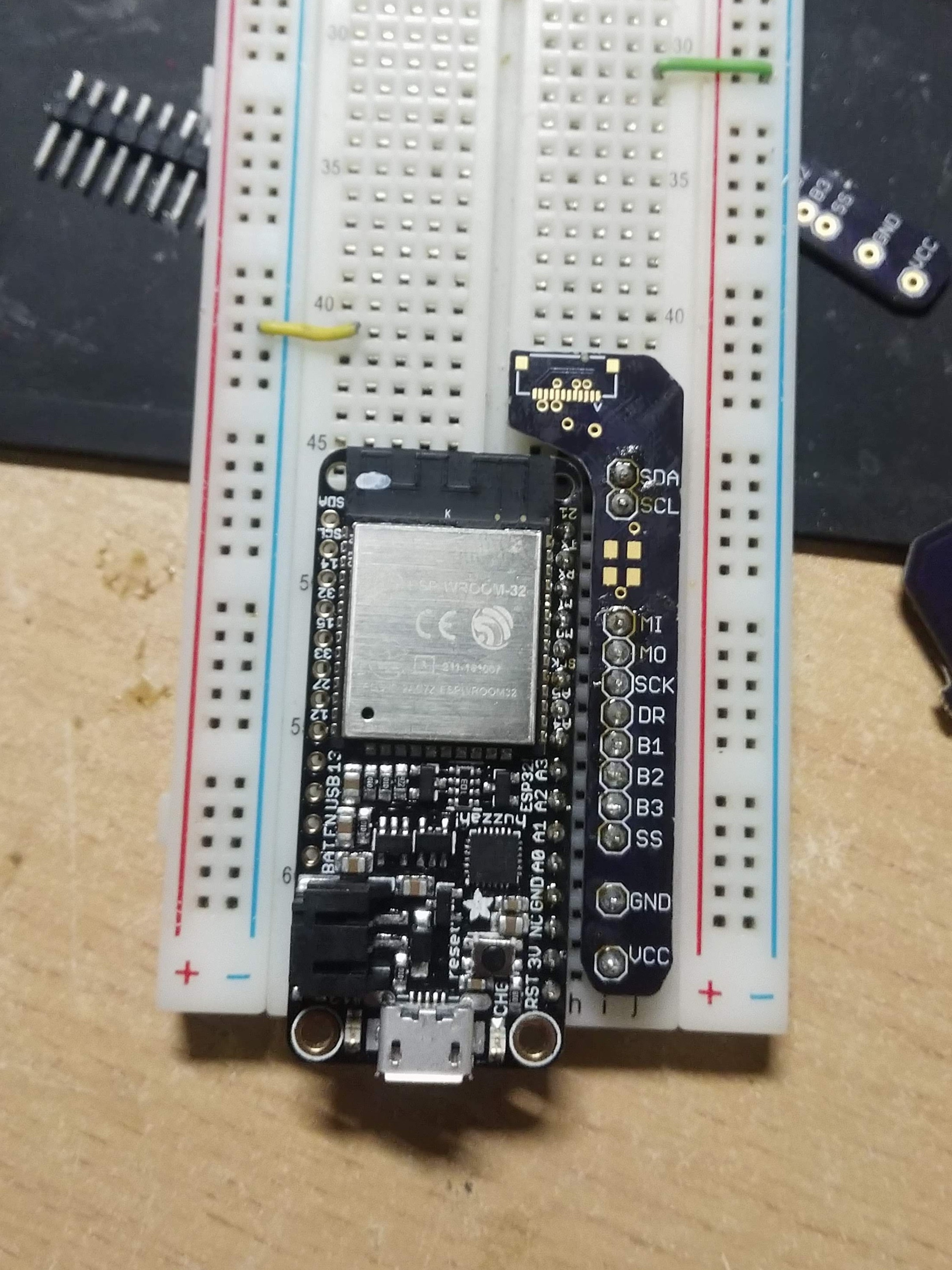
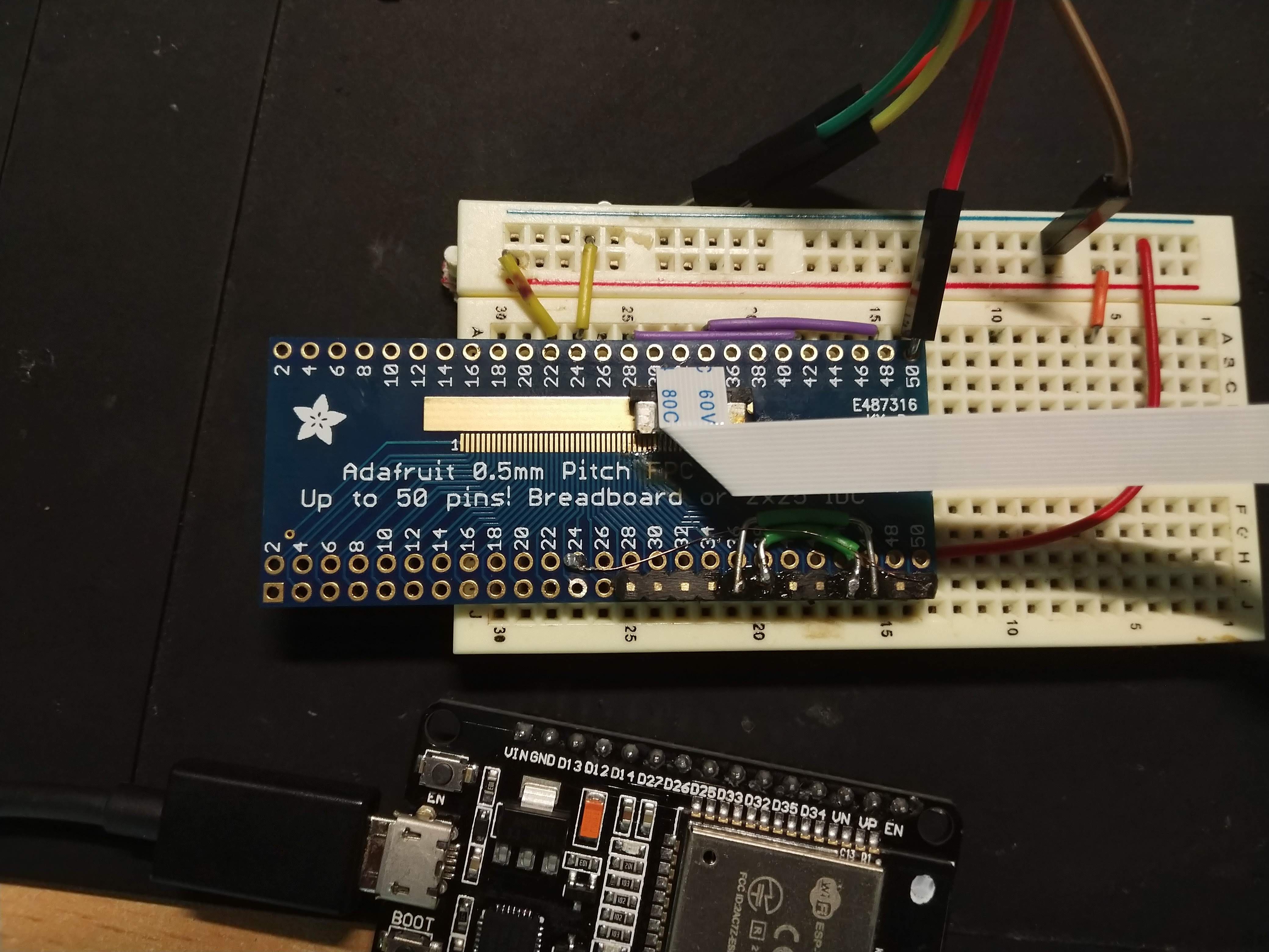

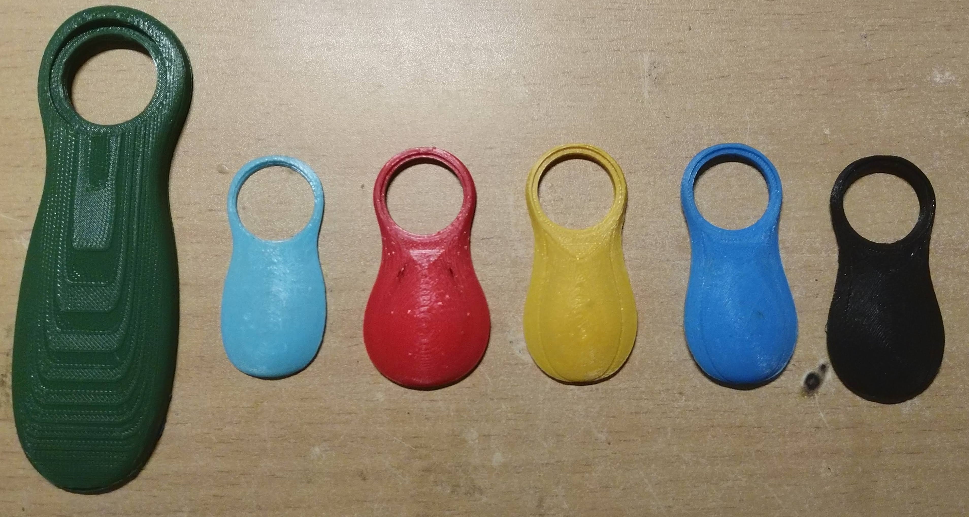
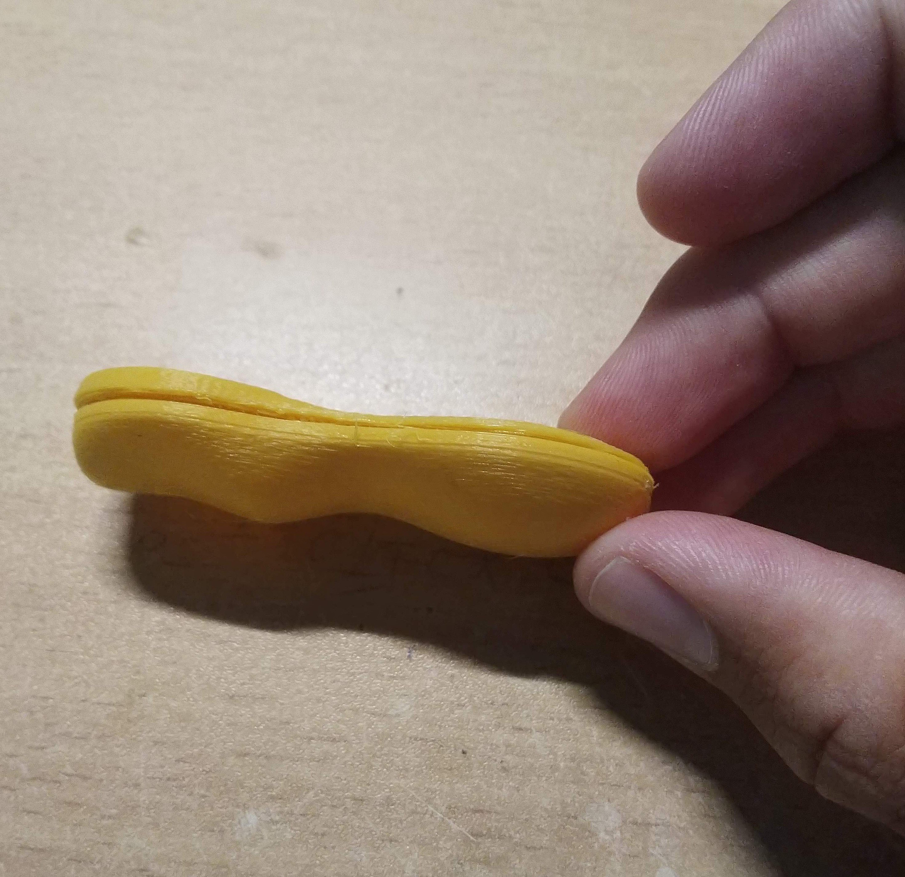 Only time will tell just what the most comfortable way to hold such a device will be. Within the next few weeks I will be getting everything bread boarded and figured out


 Matthew Peverill
 Chris Low
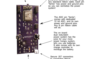
 Casual Cyborg
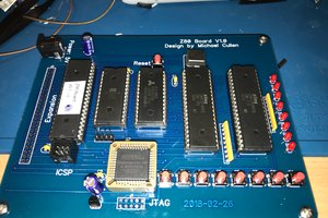
 Michael Cullen
Do you have the pcb file for the breakout board on hand?