Close
0%
0%

FPGA Bootcamp #0

If you need a refresher for digital logic before tackling FPGAs, this is the bootcamp for you!

Similar projects worth following
Even though this is an FPGA bootcamp, we won't be talking about FPGAs! Instead, this is a prelude to the other FPGA bootcamps that will give you a quick refresher on digital logic. If you can explain what an XOR gate, a JK flip flop, and a Johnson counter are, you can probably skip over to Bootcamp #1. However, if you want a quick refresher, press on! You won't need to install any software or have any hardware to do this bootcamp because we will use the excellent Falstad simulator online (http://falstad.com/circuit/). You'll be able to try the circuits we are talking about and make your own modifications.We will talk about AND, OR, NOT, and XOR gates. We will also cover flip flops and study examples, including a hypothetical car wash machine and a traffic light.

Just about everything has a computer in it these days. Computers are one form of digital logic, but by no means the only kind. Digital logic circuits appear everywhere. Sometimes they are parts of a computer system and sometimes they are completely independent. 

Digital circuits or digital logic are primarily concerned with circuits that are in two states: 1 or 0. That 1 or 0 might represent something on or off or a yes/no answer. We might gather lots of those states together to represent numbers or even letters. The key is that the state of the circuit has two discrete states.

Contrast this to analog electronics. An audio signal could have any number of voltage values. An audio amplifier might output 3V and then 3.05V and then 3.1V. Later, it might output 1.2V. All of these are legitimate values. However, it also makes them prone to noise and other effects. For example, if the 3V output gets 0.1V of noise impressed on it, how do we know it isn't the 3.1V signal? We don't. FOr most analog devices, a little noise doesn't hurt much but if you were -- say -- trying to do math by adding two voltages that 0.1V of noise would contribute to getting you the wrong answer.

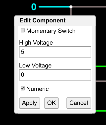
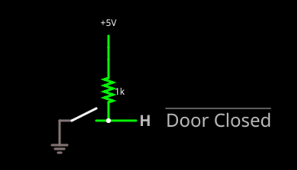
With a digital circuit, there will be some threshold value, usually a voltage. For example, I might decide 0 volts is the 0 state and 5 volts is the 1 state. I could then arbitrarily decide anything under 2.5V is a 0 and anything above 2.5V is a 1. This will offer a lot of noise immunity. Even one volt of noise plus or minus won't affect the circuit at all.

This is the fundamental reason digital electronics are important. Anything that has an on/off characteristic is a natural fit. But by grouping these exact states together we can form very complex logic circuits that will work repeatably like a computer. For example, you can ask your computer to display an exact shade of red because -- for most software -- you can specify 256 values for each color component. Imagine if you had a red light bulb and a knob that made the light brighter or dimmer. That would be an analog device and it might be difficult to get a precise brightness from such a device.

This bootcamp is part of a series:

Bootcamp 0Covers basic digital logic concepts with simulations (this bootcamp)
Bootcamp 1Introduction to FPGA coding and simulation with combinatorial logic 
Bootcamp 2More FPGA coding and simulation with flip flops (sequential logic)
Bootcamp 3Working with actual FPGA hardware

When you are ready, move on to the steps and continue on your FPGA adventure! You'll also find background articles in the project logs. You might want to browse them first and refer back to them as you work through the steps. The logs also have a glossary you can check for any unfamiliar terms.

  • Smarter Digital Troubleshooting and Analysis

    Al Williams07/16/2018 at 21:54 1 comment

    As you read digital logic diagrams to try to understand them or if you ever find yourself probing an actual piece of hardware (hard to do on an FPGA, although with built-in logic analyzers and simulators, it is possible), here's a time saving tip.

    Suppose you have a 9 input AND gate. If you probe the inputs you can stop as soon as you find a zero. Any one zero on the input means the output is zero. There's no other way it can be. Or, in the case of a NAND gate, it is a one, of course. The same goes for an OR or NOR gate. If you find a single one input, you can stop looking at the rest of the inputs. You know what the output has to be.

    During design, we (or the FPGA compiler) can often take advantage of "don't care" states which are usually represented as an X. For example, you might see a truth table like this:

    EnableInputOutput
    101
    110
    0X0

    You can interpret this as "when enable is 0, the output is 0 and the input doesn't factor into anything." 

  • More on Negative Logic

    Al Williams07/16/2018 at 21:33 0 comments

    In the main portion of the bootcamp, I mentioned that taking the OR of two active low signals was the same as performing an AND on them. In other words, if you have two door sensors that go low when the corresponding door is open, and you want to know when door 1 AND door 2 is open, you can do one of two things:

    1. Invert the signals and take the AND. This is potentially inefficient.
    2. Use a NOR gate.

    Of course, if you wanted the output to be also negative (that is low means true), you could use a NAND or OR gate, as well.

    Just like you often see little circles on flip flop inputs to indicate negation, you sometimes see the same thing on logic symbols, as well.

    For example, as in the image above, a NAND gate is sometimes drawn as an OR gate with two circles on the inputs. The gate is still a NAND gate. It is simply communicating that the inputs coming in are active low. You might even see a OR gate with two circles on the input and one on the output (which is really an AND gate).

    With the advent of computer drawing tools, you don't see this as much as you used to, but you will see it on occasion. It really does help if you are trying to understand what's going on while reading a logic schematic.

  • Acknowledgment

    Al Williams07/16/2018 at 21:04 0 comments

    This bootcamp relies heavily on the excellent Falstad simulator. Many -- but not all -- of the examples are straight from the simulator's circuits menu or modified from that source.

    You should know that the simulator doesn't do just digital electronics. In fact, that's probably the least of its capabilities. It also can model DC, AC, and even RF circuits.

    While it won't help you in the FPGA world, if you wondered how things like NAND, OR, and XOR gates are actually built from devices, it is worth checking out the Falstad Circuits menu under logic families. TTL and CMOS are the most useful to look at and you'll see how fundamental gates are made from basic devices. You don't need to do this to progress through this bootcamp, but if you are interested and have a good grounding in transistors (no pun intended), it is a fun detour.

  • Logic Minimization

    Al Williams07/16/2018 at 20:59 0 comments

    If you are here for a refresher on digital logic, you might have had a traditional class sometime in the past. It might surprise you that we haven't talked about Karnough maps (K-maps) or Quine McCluskey diagrams. It turns out that since we are preparing for FPGAs, these things aren't so important. To understand why, you have to look back at the history of digital electronics.

    Early logic circuits used relays, tubes, and transistors to build logic circuits. It is true that you could custom build anything you wanted, but smart designers realized that wasn't efficient so instead they would make a card with a few gates on it. For example, I might make a card with 6 two-input NOR gates on it. Then I would have a backplane full of cards. My goal, then, was to figure out how to make everything out of two-input NOR gates. That led to things like this Digital Equipment Corporation backplane:

    (Photo credit: Dave Fisher Creative Commons Attribution-Share Alike 3.0)

    Later, you could get ICs that had different kind of gates to them. Now optimizing to one kind of gate wasn't as important as minimizing down to the least number of packages. With FPGA design, you actually have gone back to the old days. There's generally just a few types of circuits available on the FPGA. There's just lots of them. But instead of a backplane, the connections are made with some sort of configuration memory. The circuits, though, are usually much more complex than just a NOR gate. 

    Luckily, the HDL compilers will handle all of that for us. We can describe what we want and -- mostly -- you don't have to be very concise or efficient. Well, at least until you do have to. There are certain "bad practices" we'll talk about in future bootcamps that can lead to bad FPGA designs. But for the most part you can describe what you want even in a very high-level way and the compiler will figure out how to make the virtual spaghetti backplane you need. 

  • Glossary

    Al Williams07/13/2018 at 22:31 0 comments

    • AND Gate - A gate who's output is 1 only when all inputs are 1.
    • Combinatorial Logic - Logic that does not rely on the previous state of the system to set the current output state.
    • Exclusive OR Gate - See XOR Gate.
    • Flip Flop - A circuit element that can take one of two states (1 or 0) and remember it until changed. Somewhat like a one-bit memory device.
    • Inverter - See NOT Gate.
    • Logic Diagram - See Schematic.
    • NOT Gate - A gate that takes a single input and inverts it. That is, a 1 becomes a 0 and a 0 becomes a 1.
    • OR Gate - A gate who's output is a 1 if any inputs are 1.
    • Schematic - A diagram of a logic circuit  made up, usually, of logic symbols for fundamental gates.
    • Sequential Logic - Logic that typically uses flip flops and the current output state influences future output states.
    • Truth Table - A table showing a logic circuit's possible inputs and the outputs that will result.
    • XOR Gate - Exclusive OR gate. A two-input gate that sets its output to 1 if either input is a 1, but not when both inputs are a 1.

    Logic Truth Tables for Two-Input Gates

    ABANDORXOR
    00000
    01011
    10011
    11110

View all 5 project logs

  • 1
    ▇▇▇▇ Get Familiar with the Simulator ▇▇▇▇

    We are going to use an online simulator to develop logic circuits called the Falstad simulator. It is actually very handy as it can simulate lots of different kinds of circuits, but we are only going to use some of its features.

    When you go directly to the simulator, you'll see this screen:

    Starting Fresh

    Usually, I'll give you a link to a circuit that's already built. However, it is good to know how to operate the simulator directly. As you can see, there's always a simple analog circuit when you open the page. First thing to do is get rid of it. Click on Circuits and then Blank Circuit.

    Now you have a  blank page to work with. Note how RUN is in upper case and bold?

    That means the circuit is live. If you ever accidentally stop it (the STOP will be upper case and bold) then the circuit won't work until you press run. You might use that button to pause a simulation, but usually just leaving things running is fine.

    By the way, if you click on a link to view a simulation I've already set up for you the simulator may show the circuit off to one side of your screen or perhaps even entirely off your screen. To correct this, select Edit | Center Circuit from the simulator's menu.)

    Adding I/O

    A blank page isn't very interesting. Right click anywhere in the black area (by the way, the Options menu will let you pick a white background if you prefer). You will see a menu appear that will let you pick components to place. We will mostly be interested in Logic Gates, Input and Output along with Digital Chips.

    For now select Logic Gates, Input and Output and pick "Add Logic Input." 

    Then use your mouse to click and drag. Where you click will become a terminal and the far end of the drag will say L. Make the length as you please and let go of the mouse button. The whole thing should look something like this:

    The L stands for low which is another way of saying 0 -- one of the two logic states. If you click on the L, it will turn to an H which stands for high -- a logic 1. Each time you click, the input will change from L to H or H to L. In addition -- if you don't change the options -- a wire carrying a high logic level will appear green. A logic low wire will appear gray. Put another input down next to the first one like this:

    You shouldn't have to select the menu again. Just click and drag. You can make as many inputs as you want until you pick another component type from the menu.

    You might have noticed on the menu that next to the text "Add Logic Input" there was an "i." That's the keyboard shortcut. The shortcut for "Add Logic Output" is an "o." Try adding two outputs that line up with the inputs. Instead of selecting the menu, just press "o" and then click and drag. But before you do, let's think about where to put them. You'll want to click somewhere near the inputs and then drag away (to the right). See the next section if you want to know where to click or try it and then you can always delete anything you want to change after you read the next section.

    Wiring

    If you click directly on the terminal, the output will automatically connect to the input. Normally that isn't what you want, but in this case we do. Try drawing one connected output by clicking right on an input terminal and dragging. Then create the second output near the second input but not connected (like in the figure above). Here's what it should look like:

    To connect the input and output terminals you need a wire. You can select "Add Wire" off the right click menu or you can press its shortcut "w." Once you've picked the wire you can click on one terminal and drag to the other.

    If you make a mistake, just click on the element you want to remove and use the Delete key. Control+Z will undo your last action, too. The Edit menu has the usual entries like cut and undo, as well.

    Once you have connections made, you can click on the inputs and you'll see the corresponding outputs will change. When you make an input H you will see the entire wire will turn green. If not, you probably didn't make the connection the way you thought.

    You should wind up with something that looks like this link (the final image in the animation above). Obviously, you might have your positions and lengths a little different and that's OK.

    By the way, sometimes you want your diagrams to show 1 and 0 instead of H and L. You can right click on the input and select Edit and check the numeric box if you want that effect. It doesn't change the operation of the circuit, though.

    Next Steps

    Having an input tied to an output is not much of a logic circuit! In the next step we will do something more interesting. You can go ahead and select Blank Circuit from the Circuits menu to get ready for that.

    By the way, because the simulator totally in your browser, it is hard to save your work. If you look on the File menu, you can see there are several options to export your circuit as a link, in a file, or as text. You can also import text or a file. In the case of the link, just clicking on it loads the circuit which is what I use for the example links in this bootcamp.

  • 2
    ▇▇▇▇ Understanding Basic Logic Gates ▇▇▇▇

    Open the simulator using this link and you'll see the three fundamental logic gates that will build up just about all kinds of logic. To the left are two logic inputs and each gate has its own output. Remember, you can click on the inputs to change from 0 (L) to 1 (H) and see the results.

    You can experiment and find the truth table -- a table that shows the outputs for all possible inputs -- for each gate. I'll call the top input "A" and the bottom input "B":

    Inverter:

    AOutput
    0/L1/H
    1/H0/L

    The inverter or NOT gate just flips the input to the opposite state.

    AND:

    ABOutput
    000
    010
    100
    111

    In English, this gate says that the output will be true (or high) only if A AND B are 

    both true.

    OR:

    ABOutput
    000
    011
    101
    111

    In English, this gate says the output will be true if either A or B is true.

    Multiple Inputs

    The inverter always has one input, but an AND or OR gate can have as many as you like as long as there are at least two. In the simulator, if you double click a gate that can have more inputs, you will see a dialog that lets you set the number of inputs you want. 

    In the case of an AND gate, all inputs -- no matter how many -- have to be high/true/1 for the output to go high. For an OR gate, any input high will set the output, no matter how many inputs there are.

    Assertions

    In general, you'll hear people use the words 1 and high used interchangeably to mean a logic 1. However, there is another phrase you'll often hear: asserted. This phrase is a bit tricky. Suppose I have a door open sensor that is a pull up resistor and a normally open switch to ground. When the door is closed, the switch will engage and the output will be low.

    Note the bar over the signal name "Door Closed"? That means the signal is inverted. So a low means the door is closed and a high means it is not. We would often say a signal is "asserted" and in this case that would mean the door IS closed, which is a low. You might also hear the signal is "true" when it it low, although you can't always be sure as sometimes people will say "true" meaning 1. 

    Notice this is all in how I choose to name things. If I called the signal "Door Open" it wouldn't need a bar and asserted would then be high even though the circuit didn't change at all. 

    Because it it hard to draw bars over things when typing, you'll sometimes see other ways to indicate a negative true signal:

    • a leading slash (/Q)
    • a lower-case n prefix or suffix (nQ or Q_n)
    • a trailing  # (Q#)
    • an "_B" or "_L" suffix (Q_B or Q_L)

    A Practical Design Experiment

    Suppose you had a black box that connected to the door sensor that chimes when the door is open (that is, the sensor output is high). We have a requirement to add a second door. What logic gate would you use to make the chime sound if either door opens?

    Your answer should be an OR gate. If either sensor goes high, the output goes high and, thus, the chime sounds.

    Now, suppose the black box chimes when the signal is low (that is, the door is closed). We want to chime (low input to black box) if either door is closed). An OR gate won't do it now because the logic is reversed.

    The truth table for our function is:

    Door 1#Door 2#Chime#
    000
    010
    100
    111

    If you look back in the next section, you'll see that this is an AND gate. In fact, for inverted inputs, and AND gate will act like an OR gate and -- you can probably guess -- an OR gate acts like an AND gate.

    You don't need to remember the name, but this is Demorgan's theorem. You could have got the same effect by inverting the inputs and then using the gate you'd expect (that is, an OR gate). Then you'd have to invert the output to send to the black box. So now you'd have 4 gates where 1 would do the job.

    Minimizing logic like this used to be a big part of digital design. Now (in future bootcamps) we will describe what we want and the computer will figure out the most efficient way to implement it.

  • 3
    ▇▇▇▇ More Advanced Logic Gates ▇▇▇▇

    This circuit is similar to the previous one, but it show two new gates: NAND and NOR. These are simply an AND gate and an OR gate with an inverter at the output. So where an AND gate will output a 1, a NAND gate will output a 0. Obviously, you can make these with two gates and the symbol suggests this (an AND or OR gate with a little circle at the output). However, these can often be implemented as a single gate, so it is handy to have symbols for them.

    Here's another circuit with a different composite gate.

    See the bottom gate that looks like an OR gate with an extra line? This is a two input gate that has a high output if either input is high, but not both. The three gates at the top (an OR, a NAND, and an AND) implement the same function. That proves that you don't have to have an XOR gate, but it is so useful that it is handy to have a single symbol for it.

    This kind of gate is called an exclusive OR or XOR gate. There are two things that make it very useful. 

    First, look at the XOR truth table:

    ABOutput
    000
    011
    101
    110

    You might make two observations. If A is 0, then the output is a copy of B (or, if you prefer, if B is 0, then the output is a copy of A). But if A is 1, the output is the inverts of B (and the same holds true if B is 1, the output is the inverse of A). This makes the XOR gate a sort of programmable inverter.

    The other thing to note is that using binary addition, the output is the sum of A+B. You might wonder how 1+1=0. Well, if you answer is a single bit that's correct, but there is an extra carry bit. This circuit doesn't compute the carry bit, but it does compute the sum. In a future bootcamp, you'll see how the XOR and some other logic can add numbers together in a configuration called a half adder or a full adder.

    By the way, the top set of gates is one way to create an XOR gate. You can actually make one using several other methods (for example, using all NAND or NOR gates). So if you see a different schematic for the inside of an XOR gate, that's OK. There's more than one way to do it.

View all 15 instructions

Enjoy this project?

Share

Discussions

Zoltan Groska wrote 09/16/2020 at 21:35 point

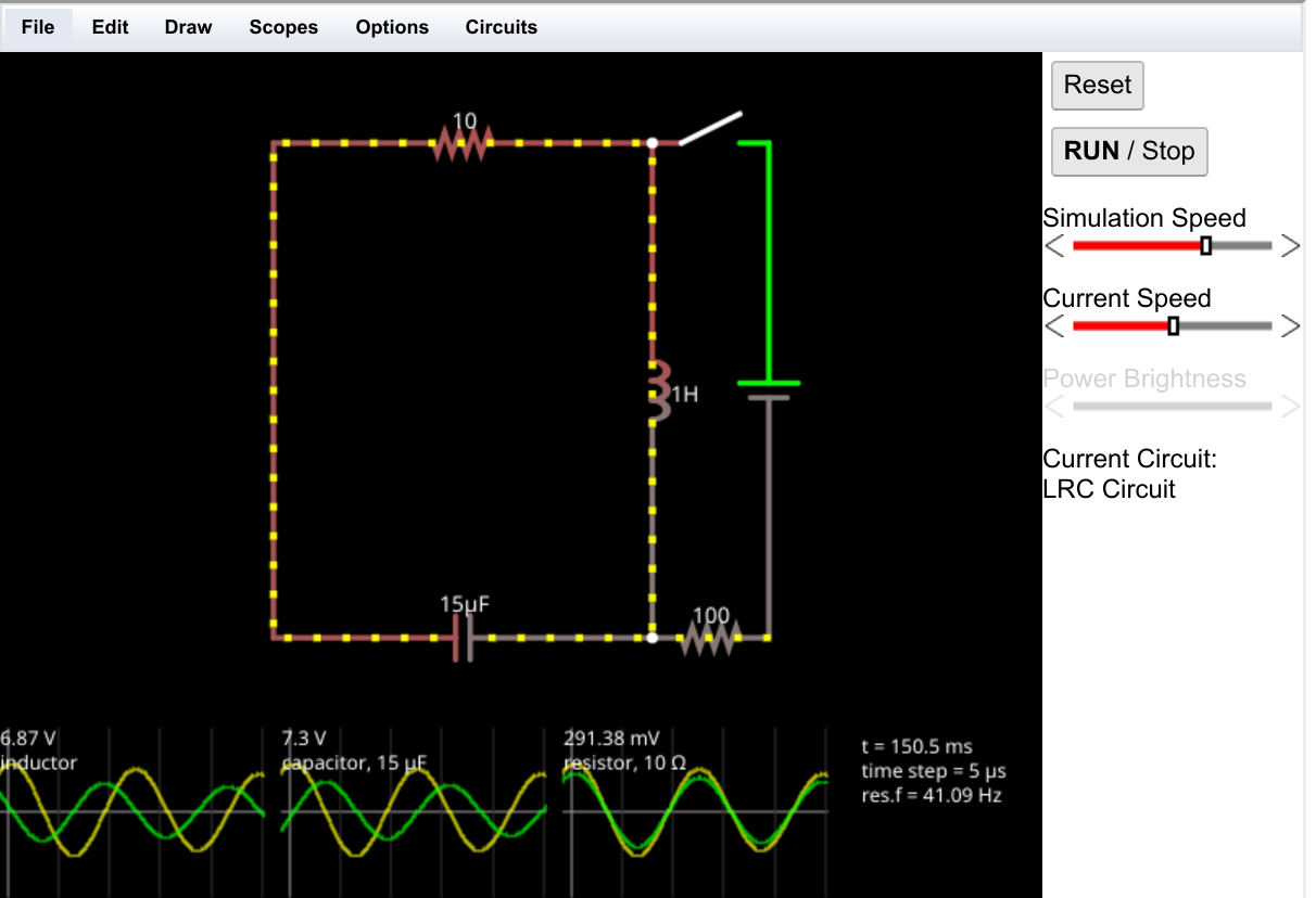
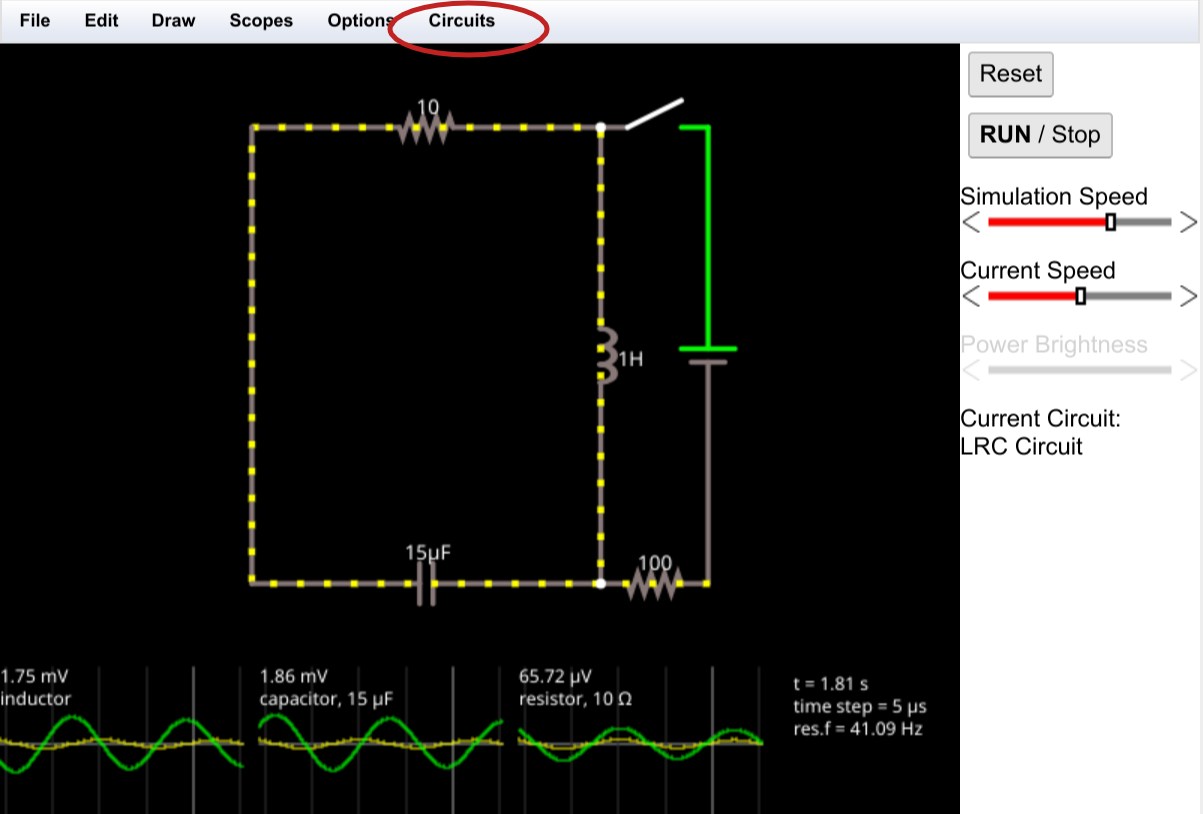
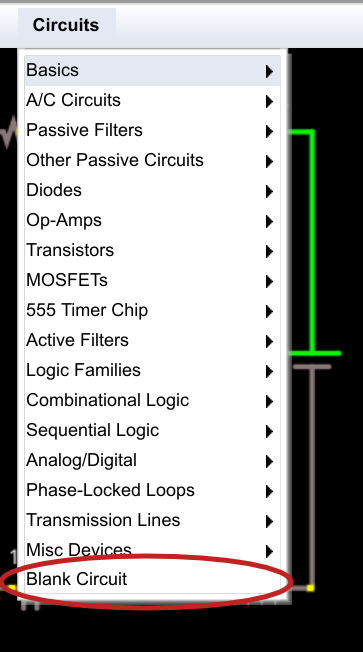
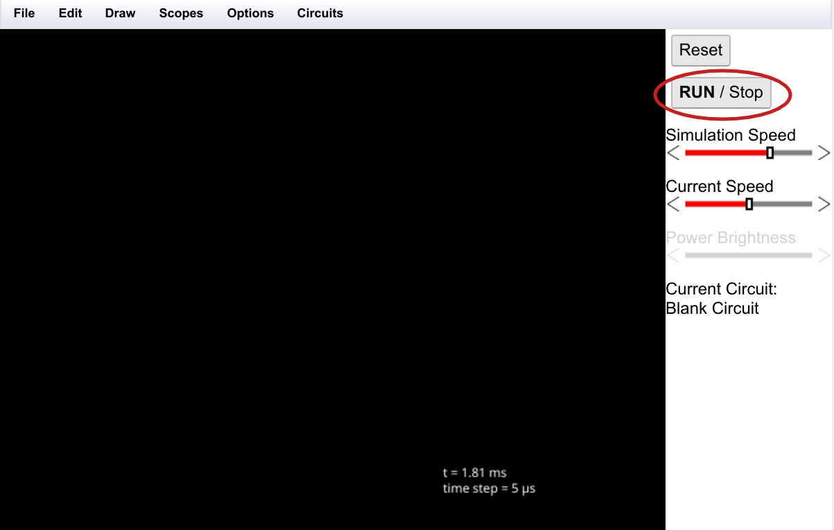
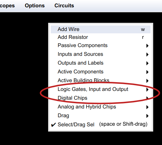
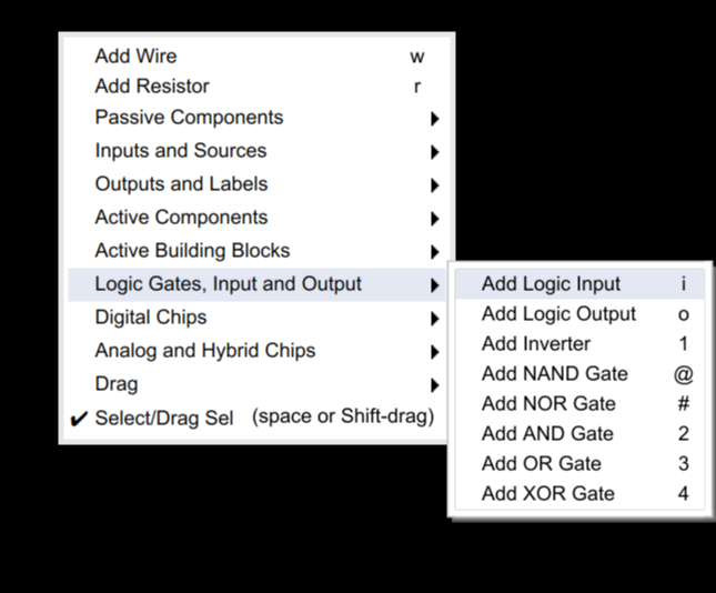
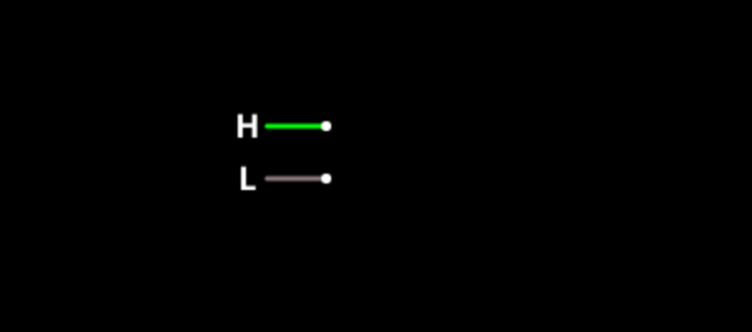
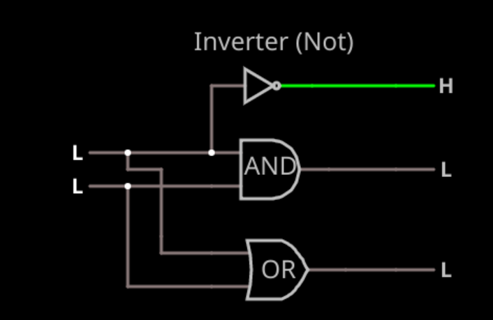
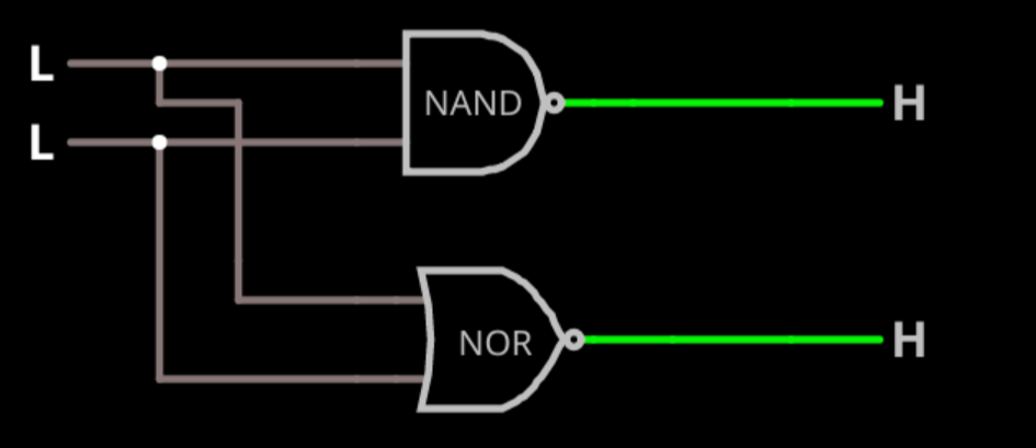
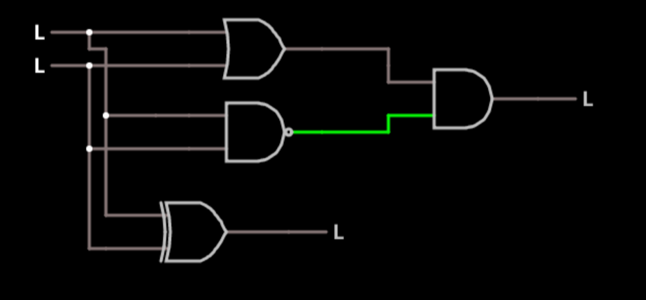
"2 ▇▇▇▇ Understanding Basic Logic Gates ▇▇▇▇ Open the simulator using this link and you'll see ..."
link error
http://tinyurl.com/y9qlmssd%E2%80%8B   --->   http://tinyurl.com/y9qlmssd

  Are you sure? yes | no

frate_g wrote 03/19/2020 at 13:49 point

Gracias por tu trabajo!

  Are you sure? yes | no

fabian wrote 08/04/2018 at 13:48 point

is any real problem?

for example i buy a usb device and put to laptop and count faster program than normal in C

  Are you sure? yes | no

Similar Projects

Does this project spark your interest?

Become a member to follow this project and never miss any updates