Close
0%
0%

SolarCharger SZBK07V2

A MPPT solar charger using a DC converter, MOSFET diode, Arduino Nano for control and an MPPT software library for simple integration.

Public Chat
Similar projects worth following
This project combines a commercial DC-DC converter with constant voltage and constant current pots (the SZBK07) and a capacity of up to 20A with contol by an Arduino Nano. The Nano controls the DC converter by PWM connected to one of the terminals of the voltage control pot. Reverse current flow into the DC converter is prevented by a MOSFET diode, which provides very low forward voltage drop for low power loss and minimal heat dissipation. The software for the Nano is mainly in a separate C-header file which can become a library, simplifying the integration of the whole into many different types of solar charger or other projects such as robots powered by the sun. Full details of the design including the project diary can be found at https://github.com/farmerkeith/SolarChargerSZBK07ModuleV2

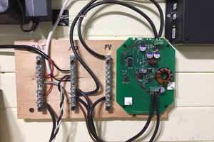
DC-DC converter connections

Control of the DC-DC converter is done by pwm input to the voltage control input of the converter. A wire is soldered to this point, the details of how to do it are at  https://www.instructables.com/id/Controlling-DC-Converter-Modules/

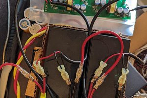
The converter has a built-in shunt resistor of 4 milliohms which is designed to be used for the current control of the converter. In this project, this built-in shunt resistor is used to measure the solar panel current. This is done by reversing the connections of the negative leads of the solar panel and the battery, compared to the usual setup.

That is, the negative lead from the battery is connected to the converter terminal marked "IN-" and the negative lead from the solar panel is connected to converter terminal marked "OUT-". This results in the solar panel current flowing through the shunt resistor.

The voltage resulting from the current in the shunt resistor is amplified by a circuit using an AD822A op amp and then connected to an analog input pin of the Arduino Nano.
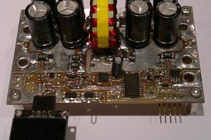
MOSFET diode

The MOSFET diode consists of an N-channel MOSFET (type PSMN3R3-80PS which has a very low ON resistance) and a control circuit consisting of 2  N-channel MOSFETs 2N7000 and two resistors.

Details of simulations of a variety of MOSFET diode configurations including this one can be found at https://github.com/farmerkeith/circuits/tree/master/MOSFETdiode

SZBK07.pdf

Schematic diagram of the solar charger

application/pdf - 35.24 kB - 07/16/2018 at 02:54

Preview
Download

  • MOSFET diode simulation and update

    keith.hungerford07/28/2018 at 13:04 0 comments

    I simulated a simpler MOSFET diode control circuit suitable for this design. The updated design uses two 2N7000 MOSFETs in the control circuit. With these MOSFETs there is no need for additional voltage protection diodes which were needed in the original design, so overall the performance is maintained with a simpler circuit.

  • System testing

    keith.hungerford07/16/2018 at 01:56 0 comments

    16 July 2018:  Solved various calibration problems with the voltage and current measurements.

    PWM control of the DC  converter appears to work well.

  • Software devlopment

    keith.hungerford07/16/2018 at 01:54 0 comments

    15 July. Working on software – initial version now complete and started testing / debugging

    Set up breadboard with Arduino,  voltage dividers and current shunt amplifier, and connected with the SZBK01. The breadboad modeel uses a schottky diode instead of the MOSFET diode at this stage to reduce build time.

  • Voltage and current measuring design

    keith.hungerford07/16/2018 at 01:51 0 comments

    14 July 2018. The hardware schematic is completed, subject to sizing of the voltage dividers and current amplifier components.  The calculations are in the spreadsheet in the project documentation on Github.

    Started working on the software.

  • Project initiation

    keith.hungerford07/16/2018 at 01:44 4 comments

    13 July 2018: I decided to try and submit an entry for the .energy harvesting competition. I have been working on this topic for some time but have not created an end product so far. My concept is to create a modular MPPT charger based on a  SZBK07 DC converter, a MOSFET diode and Op-amp current sensor using the 4 milli Ohm resistor in the SZBK01.

    Software will be a library with an MPPT class. It will be configurable for battery set points and temperature input. It will have an interface to get logging data out, so that the system integrator can add a display, local data logging or remote logging by WiFi or other technology.

    Working on the hardware schematic diagram.

View all 5 project logs

Enjoy this project?

Share

Discussions

magimahesh3198 wrote 08/04/2020 at 11:33 point

SZBK07 is giving some sound when i connect the pwm pulses to the feedback pins may i know the possible reasons.

i have used an Opamp to amplify the arduino pwm pulses and connected them to feedback pin via 20K resistor, the noise is from inductor i guess.

if possible can you please share the exact procedure to find the feedback pin and its interface with ardiuno.

thanks in advance...

may mail id:- magimahesh3198@gmail.com

  Are you sure? yes | no

Similar Projects

Does this project spark your interest?

Become a member to follow this project and never miss any updates