 Yann Guidon / YGDES
One of the displays of the panel is a counter that uses the 5 prototype #Numitron Hexadecimal display module . The display modules are ready so now comes the part with the counter.
I just made a detailed video about making a divide-by-two bistable, at the heart of a ripple counter (there is no need for something faster because it's just a user panel, unlike the PC display).
The video is light on schematics so here they are !
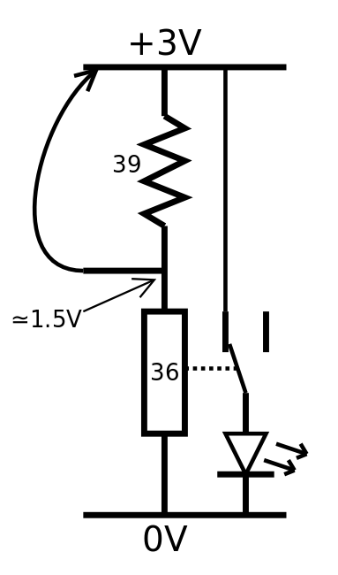
The first part shows how to work with hysteresis and the RES15 relay. This has been explored for a while now but it had to be repeated again :-)
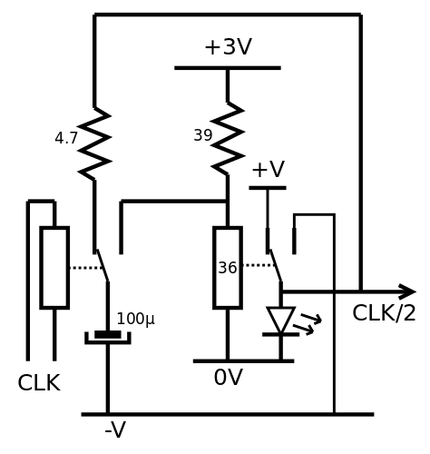
Then a second relay switches a capacitor between the output and the input of the cell. The charge is transfered through the capacitor to force a spike on the latch's coil. Notice that there are 2 power supplies : one (stable) for the latch relay and its resistor, the other for for the "charge switcher". This is because to save costs and space, the capacitor must be smaller, so a higher voltage difference is required. A small series resistor (here 4.7Ohm) limits the inrush current into the capacitor. A LED shows the state of the latch.
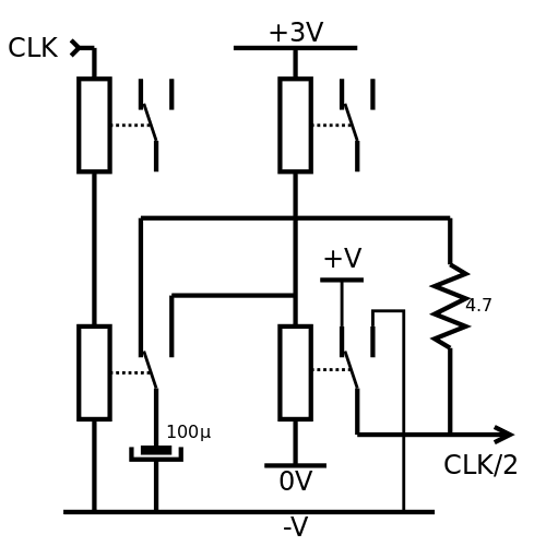
Not shown in the video : these cells can be cascaded because the latch can directly control the coil of the next cell's relay.
The output's range is higher than the latch's power supply so one or two more coils can be conncted in series, to drop the voltage and act as output(s). This series coil can be integrated inside another module, such as the #Numitron Hexadecimal display module (which has 2 wires per input, to make this stunt possible).
Another solution is to replace the 39 ohms resistor with another relay but it might be less reliable. The capacitor would have to fight 2× more inductance and the thermal drift would be higher...
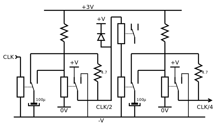
Now here is a proposed circuit that i'll have to test someday at last :-D
Discussions
Become a Hackaday.io Member
Create an account to leave a comment. Already have an account? Log In.