 Yann Guidon / YGDES
The design of the front panel has evolved lately, as shown in the latest logs of #YGREC8: A new assembler panel. The interlocked switches have brought a new "touch" and "feeling" that beats the original design with only slide switches and rotary encoders.
This "new" increase in user-friendliness makes the disassembler panel's lamps (as planned earlier) look dumb and unwelcoming... What could I do ? Add more Numitrons, of course !
The immediate field is already taken care of with the #Numitron Hexadecimal display module so the rest should be easy, right ? Kinda sortof... But at least I have developed the techniques to make it easier, cheaper and smaller to build.
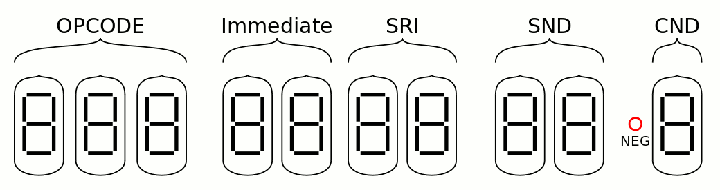
I made sure all the symbols could be represented in 7-segments displays: there are a few exceptions but the majority is unambiguous and explicit.
- The SND and SRI register name fields are identical, they take 3 address bits and 1 enable bit, to represent one of the 8 possible symbols on 2 tubes.
- The CND field is 2 or 3 bits, I squeezed the symbol in 1 tube. The negation is a red lamp.
- The opcode field is 4 or 5 bits and squeezed in 3 tubes.
That's 10 tubes now...
There are several compromises but it looks much better than the originally planned panel with the many lamps.
I wonder if/how I could share the Immediate and SRI displays. Not to save a pair of Numitrons but to further reduce the clutter...
The opcodes look OK with 7 segments and 3 tubes :
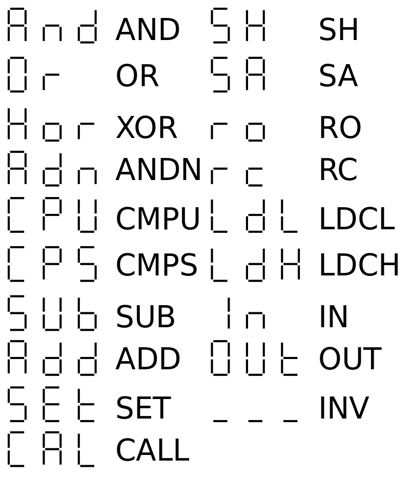
XOR looks strange but I'll live with it.
The register names are easier:
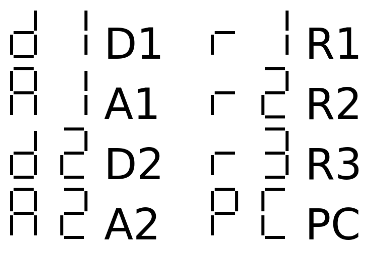
There are a few obvious tricks to apply, as we'll see later.
Last but not least : the conditions
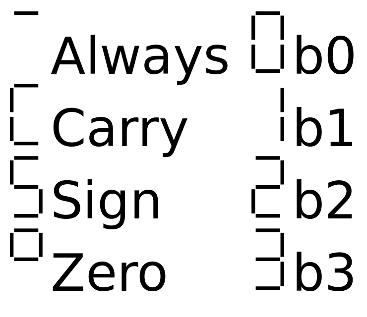
This one is a bit more tricky though because Z can't easily be represented and it would collide with 2. I also didn't want to represent Always as A, it should look inoccuous because it's used most of the time.
I adapted the design of the #Numitron Hexadecimal display module and reduced the width to 3 bits / 8 codes. It was easy because the 0-1-2-3 codes were already working so I just added the 4 other codes :-)
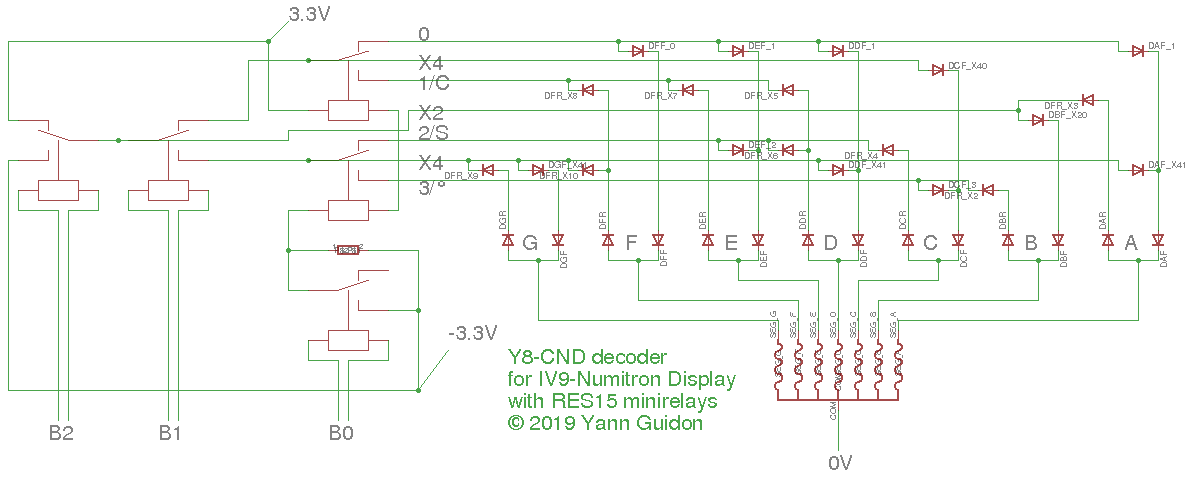
There are only 5 relays (including a buffer and BTW I forgot to put a series resistor) but no less then 14+20=34 diodes. It's a single unit so I think the prototype will be OK (and I have already solved all the possible problems). Many diodes are doubled but I can't simplify it because it would break the balance of currents&voltages.
The register names are implemented twice. Each module uses 6 relays (+2 buffers) and 26+14 diodes. I have chosen a unipolar system to simplify things, yet it can be plugged to the existing Numitron tubes, in parallel with the hexadecimal decoder. There is a weird unbalanced binary tree...
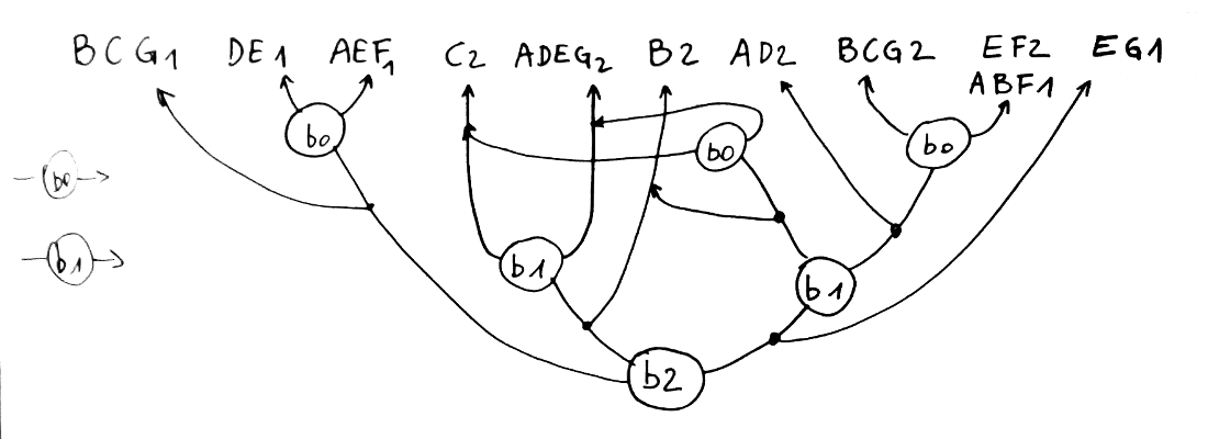
The upper line (the letters) can be a classical array of diodes, and the output can join the anti-feedback diodes of the hexadecimal decoder. But I'm not sure it's relevant to save 2×7=14 diodes anyway... however there must be a way to disable the + and - supply pins of the decoders while the Numitron tubes share the 0V supply.
As expected, the opcodes are a bit more messy...
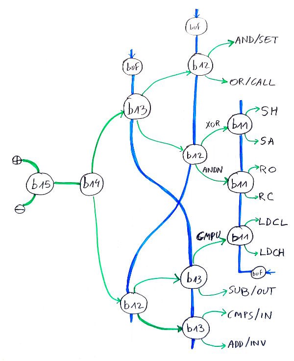
I chose a bipolar design to keep the number of relays low. There is also a fortunate coincidence : there are 3 buffer relays that each drive 3 relays (b11, b12, b13). There is a little crossover with the control lines of b13 and b12 to achieve that, which swaps SUB/OUT with CMPS/IN.
But that's it.
The equations for the segments will be another beast though... I don't know how many diodes will be necessary.
.
Discussions
Become a Hackaday.io Member
Create an account to leave a comment. Already have an account? Log In.
That is going to be awesome to work with and reading those display tubes will be a hoot :-)
Are you sure? yes | no
I'm just wondering...
How reliable will this be ?
What part will break first ? The Numitrons ? the diodes ? the relays ?...
Are you sure? yes | no