0%
0%
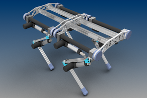
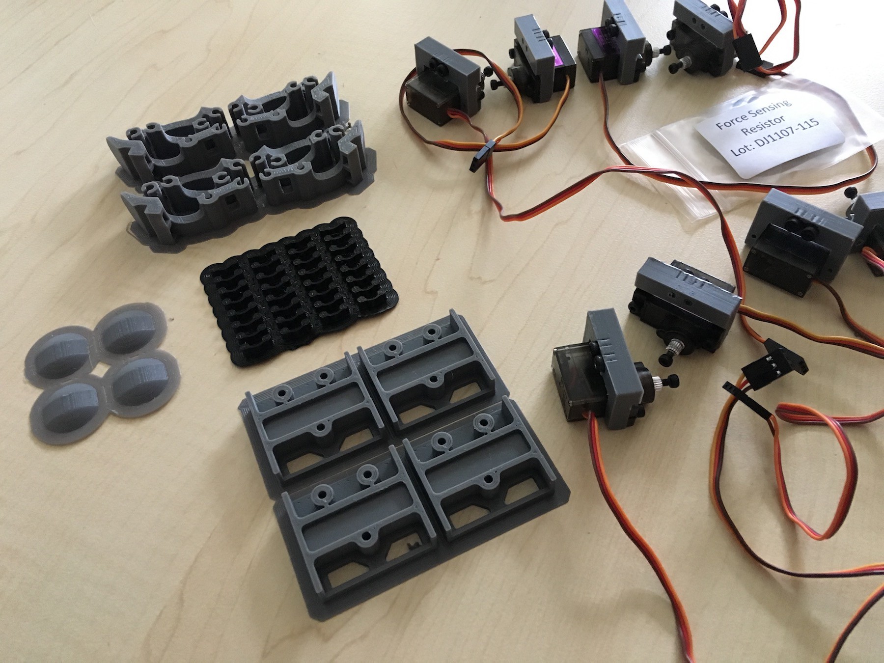
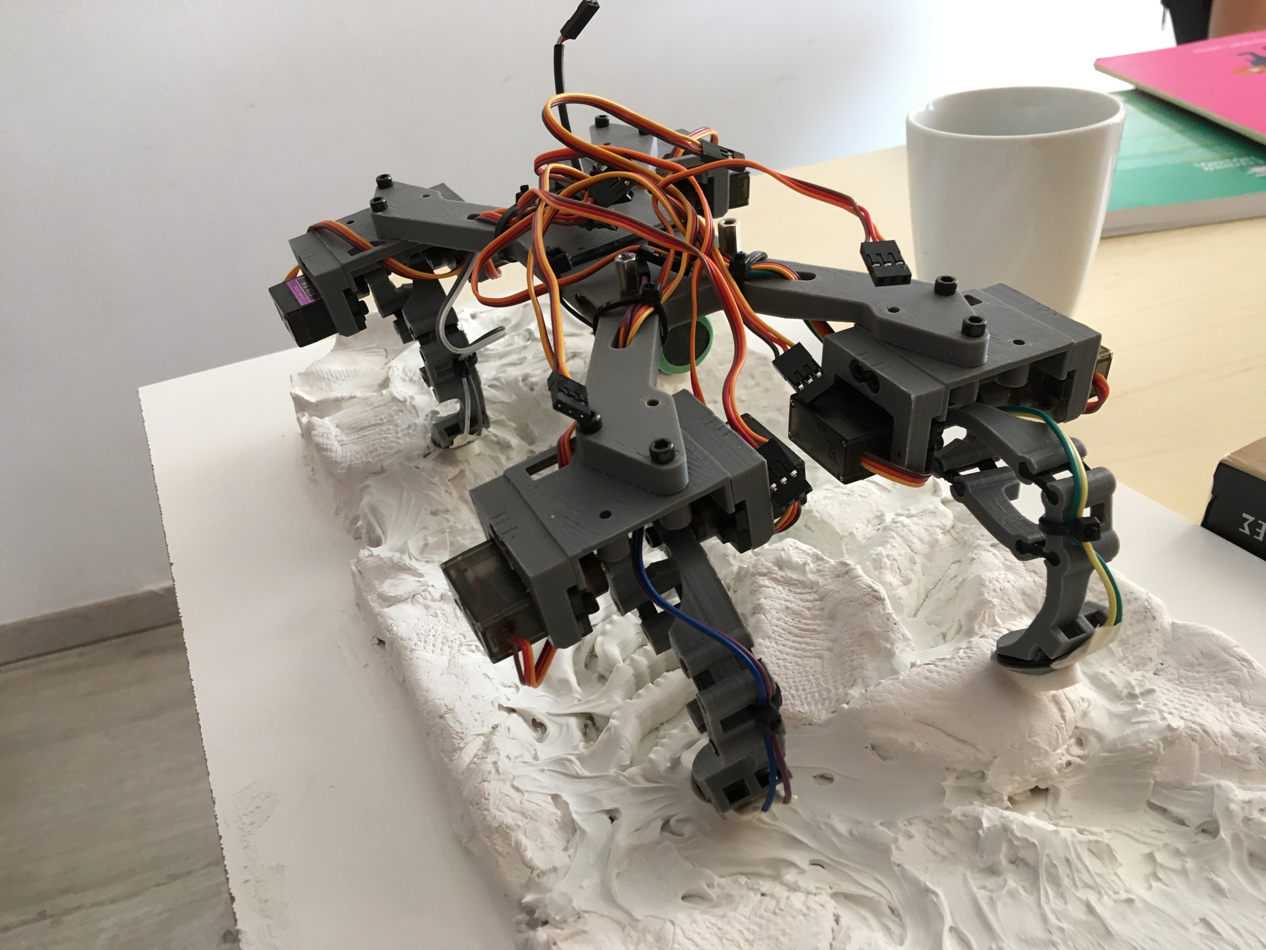
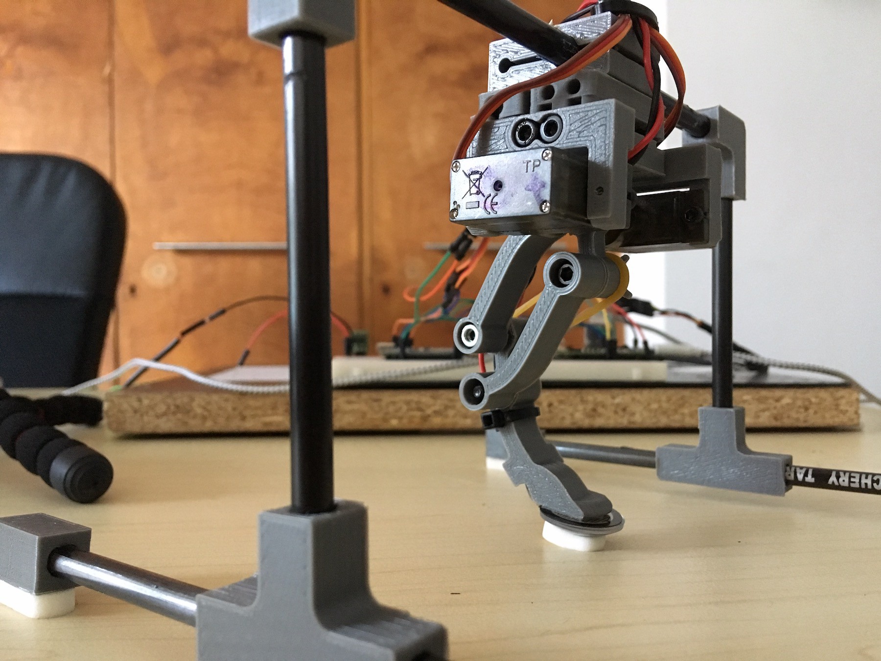
Quadruped Robot
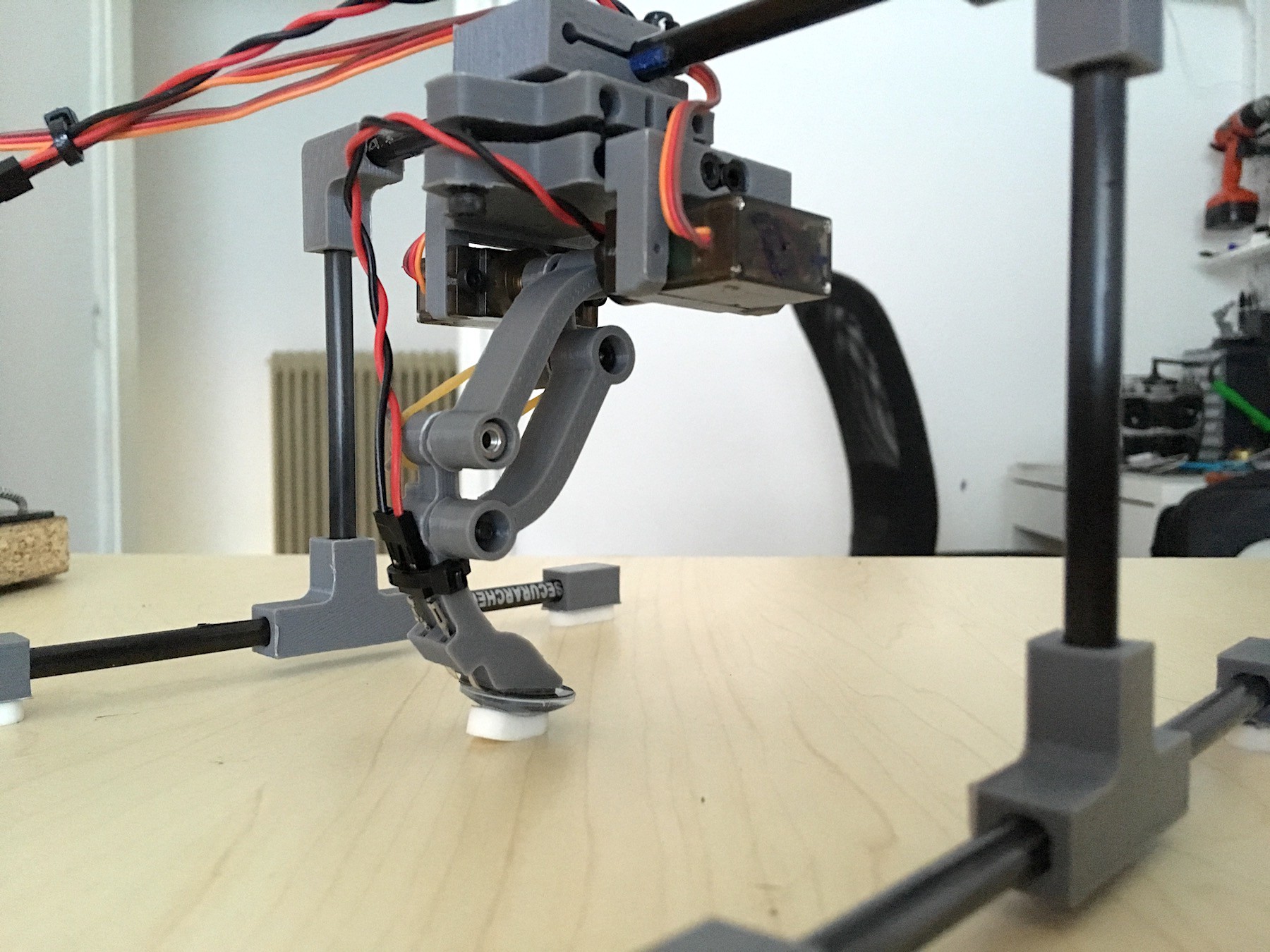
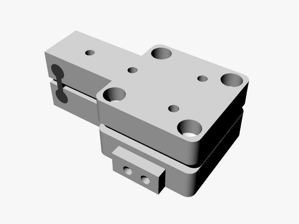
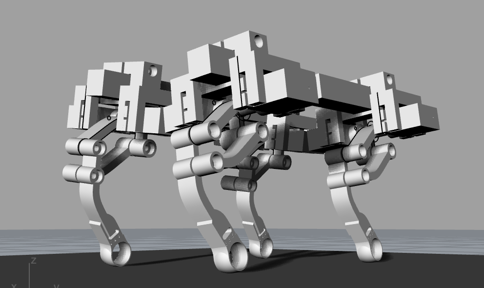
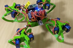
A quadruped robot using cheap servos closed-loop control and force-sensing resistors for ground force feedback. Uses Teensy and PCT.
 Yannis
Become a Hackaday.io member
Already have an account? Log in.
Just one more thing
To make the experience fit your profile, pick a username and tell us what interests you.
Pick an awesome username
hackaday.io/
Your profile's URL: hackaday.io/username. Max 25 alphanumeric characters.
Pick a few interests
Projects that share your interests
People that share your interests
 Martin Vincent Bloedorn
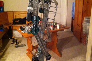
 Anthrobotics
 Aaed Musa