 Maximiliano Rojas
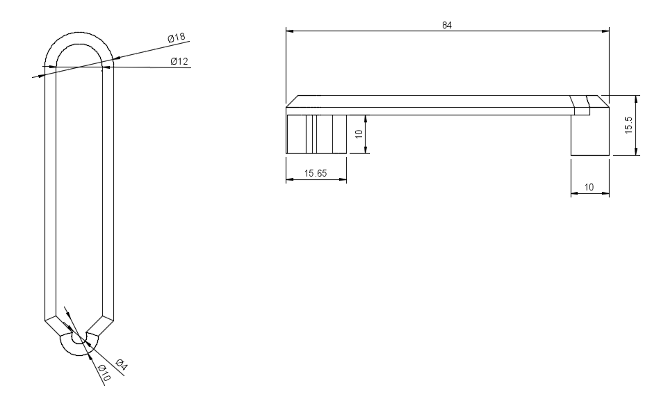
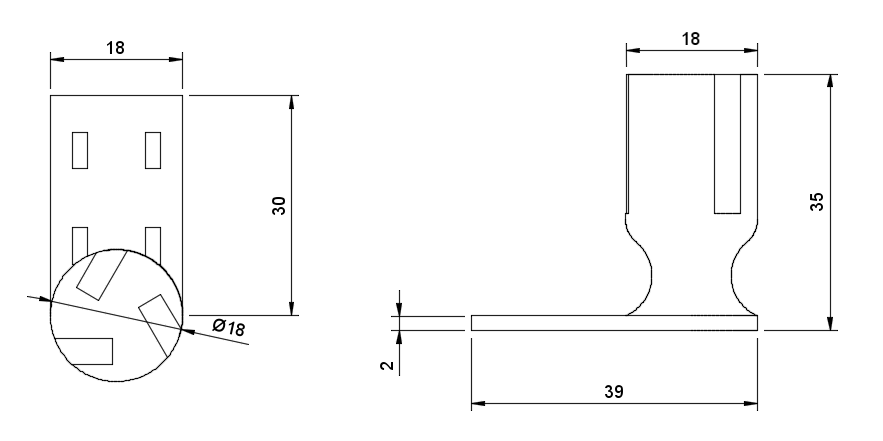
cad files here (fusion 360, and .iges files):
https://github.com/magokeanu/ModularHapticSystem
Project's structure
This project has as objective the development of a multipurpose modular haptic device of an easy implementation to any other project that requires a flexible but precise way to, for example, interact with virtual objects or a control for robotics (like a robotic arm or a robot surgery), besides to orientate the designs and construction to a minimization of cost as possible.
This must be flexible, so, with the intention to probe the concept and versability, every module being orientated to an application test, for example, pc mouse, race game control, haptics, and robotics.
In a general way, the structure of this project will be divided into seven stages, one for state of art (projects that serve as inspiration and a brief explication of some important background theory), four for modules, one for electronics approach, and the last one for conclusions and recommendations for a future improvement. The global approach will be an engineering one, considering aspects like coding, electronics, and mathematics.
General goals:
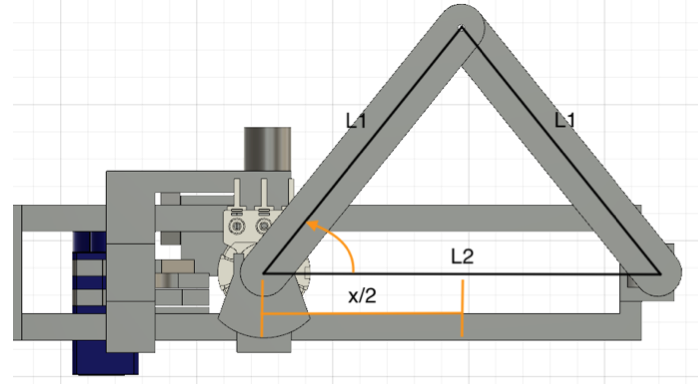
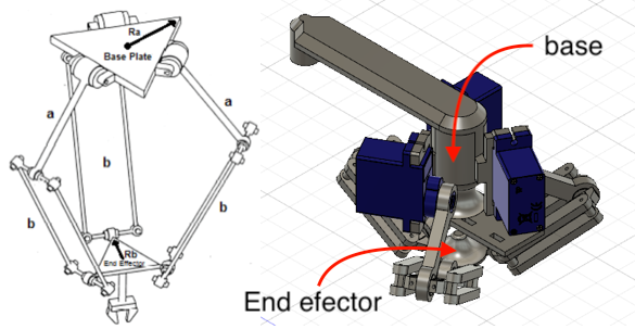
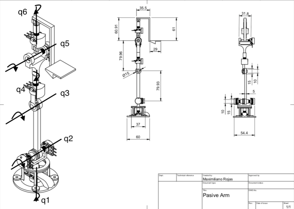
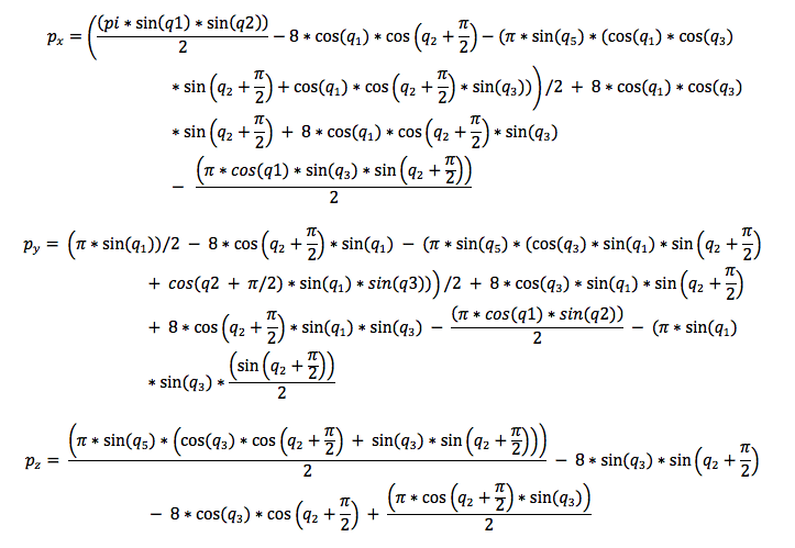
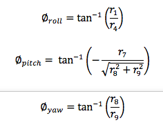
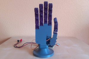
- Design and construct a passive arm that can measure through direct cinematics the 3D position and orientation of its end effector.
- Design modules orientated to VR systems, pc control, and robotics.
- Improve flexibility and portability through a portable source of power
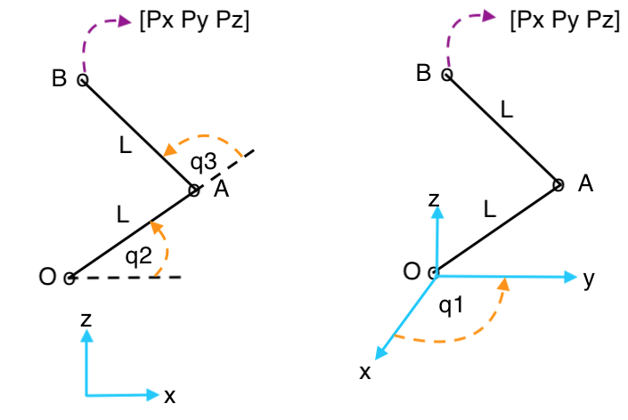

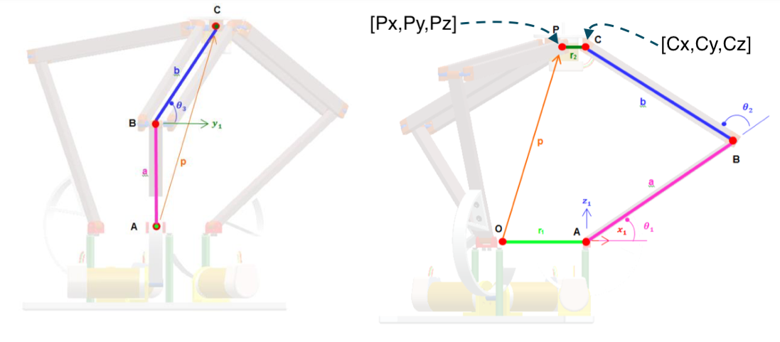

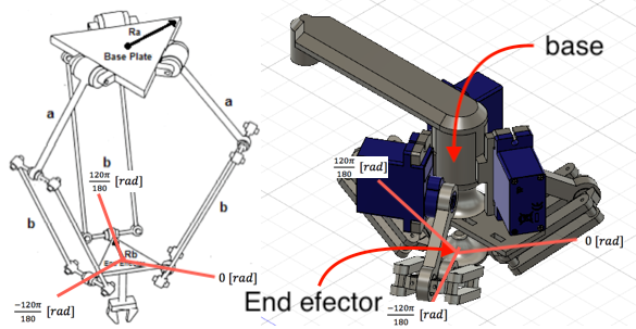


 general structure. B) Structure that will be used.")

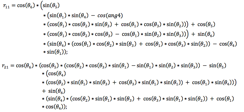
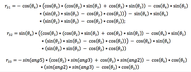
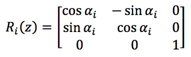
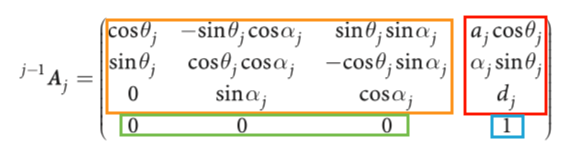
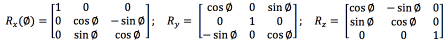
 *Extracted from Peter Corke-Robotics, Vision and Control. Fundamental Algorithms In MATLAB book, I really recommend this book in case if you want to deepen.


 Alvaro Villoslada
 NEBRA Labs
 Michael Graham
Oh wow. This is really useful, I think I might make one, eventually.
Good work!