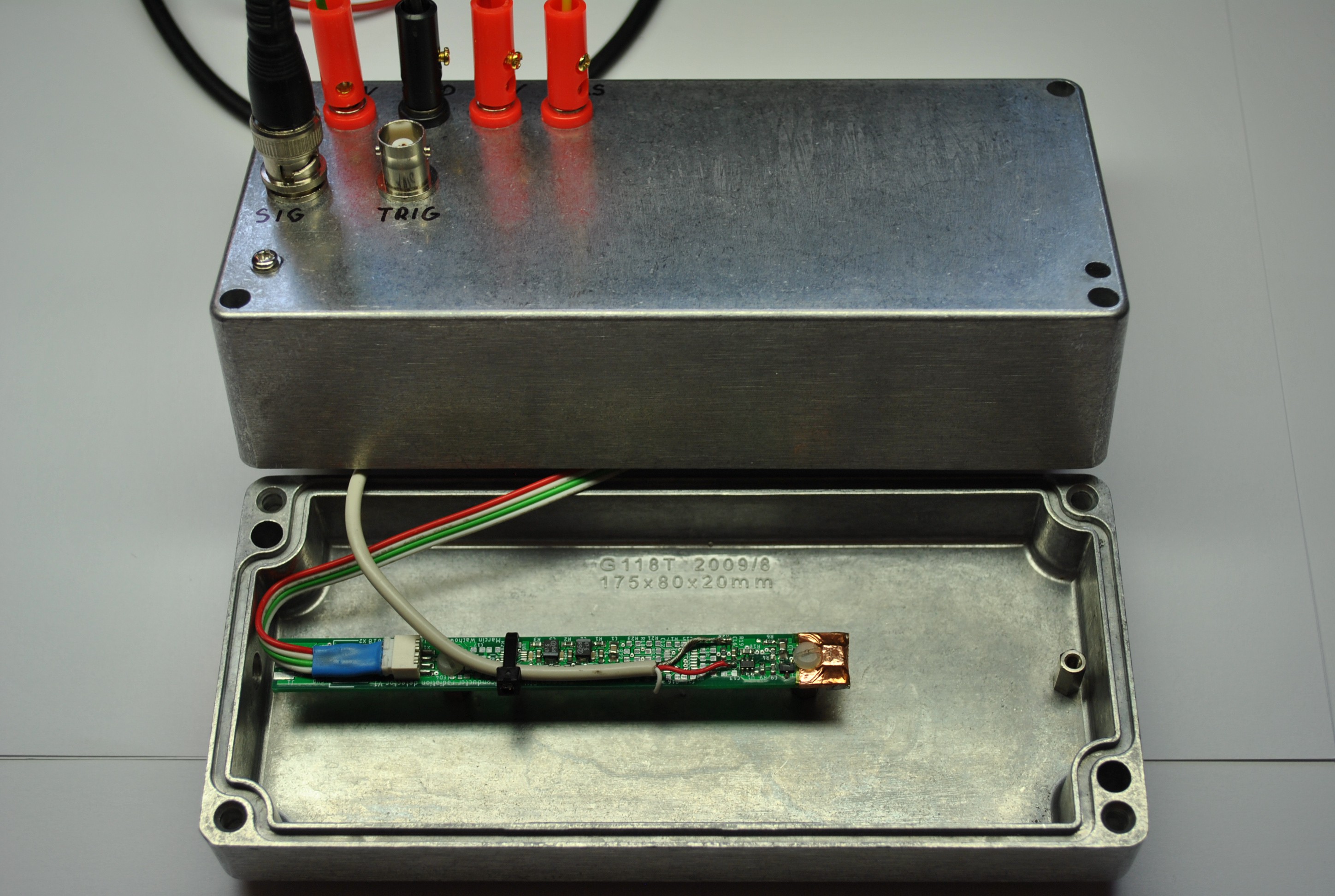
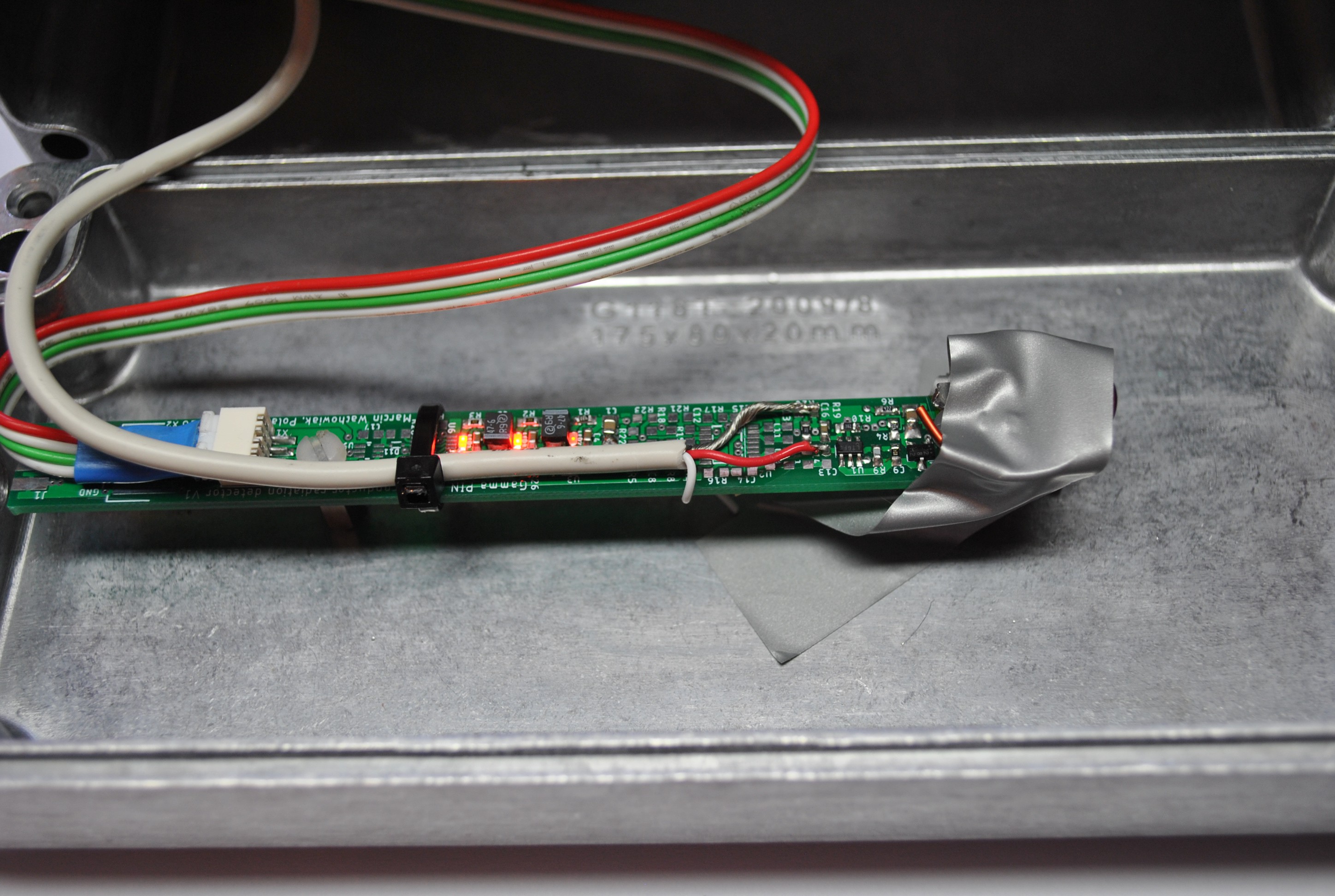
Evaluation of the preamplifier stage
To achieve the best resolution possible the charge sensing stage and its response had to be tested against various feedback resistance values. To conduct these tests, I used a source with known energy emissions. The only one I could easily acquire was Americium-241 from dismantled smoke detector. According to the Table of Radioactive Isotopes the detector should get readings of photons of energy of about 60keV (59.5412keV) which makes up for 35.94% of Am241 emissions.
Having a stable source, I was enabled to perform a reliable comparison while altering the circuitry.
Bootstrap circuit alteration and efficiency
As mentioned in previous logs I am trying to implement a bootstrapping circuit to be able to work with bigger – high capacitance detectors. Unfortunately, BF862 - the JFET used in the application note concerning bootstrapping is no longer manufactured. Moreover, the whole family of BF86X has been declared end of life. Although you might still come across it in some local shops, I had to find an equivalent to keep the project up-to-date. After a bit of searching the best, I could come up with was CPH3910 from ON Semiconductor. It has quite similar parameters and should be a fit substitute.
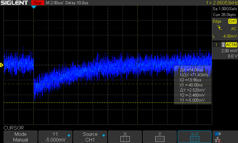
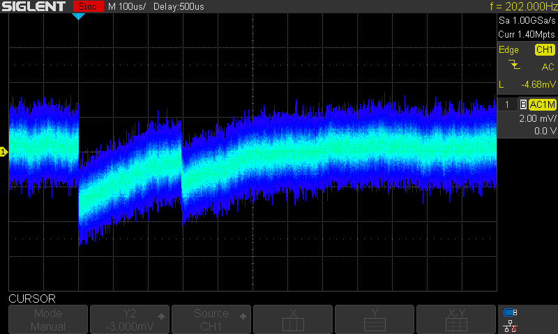
To verify whether the bootstrap improves of degrades sensitivity I performed a few tests. The tests were performed in two configurations using 1 and 10 sensing diodes, respectively with and without bootstrap. With following presets: Source: Am241 (60keV), Rf = 22M, Cf = 0.47p, Oscilloscope BW = 20MHz and operational amplifier LTC6268. Notice that the values marked with the cursors are the ones that repeated the most – the most probable.
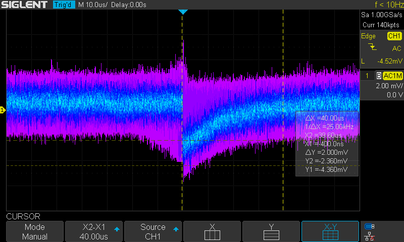
The first test: 1 PIN diode:
Without bootstrap - Bootstrap inactive
With bootstrap - Bootstrap active
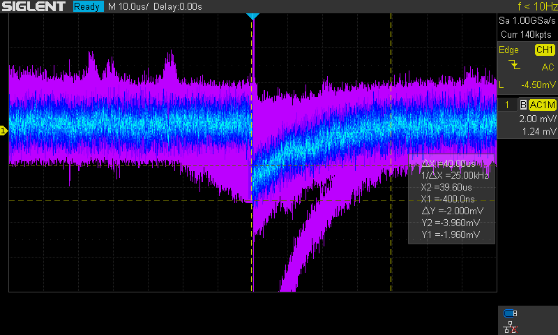
In the one diode case the bootstrap had little impact on the signal quality because of the small diode capacitance. But from the noise figures I could read that it improved the low frequency components of the signal, which are more significant as the radiation pulses are in this domain. The pulse height did not change significantly enough in any way for me to notice. On the screen from oscilloscope you might see a trace of a high energy pulse, but that was probably just some random emission from the source which
I don’t want to misinterpret. Maybe the bootstrap might have enabled the preamplifier to capture it.
The second test: 10 PIN diodes:
Without bootstrap - Bootstrap inactive -preamplifier unstable: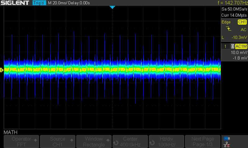
With bootstrap - Bootstrap active
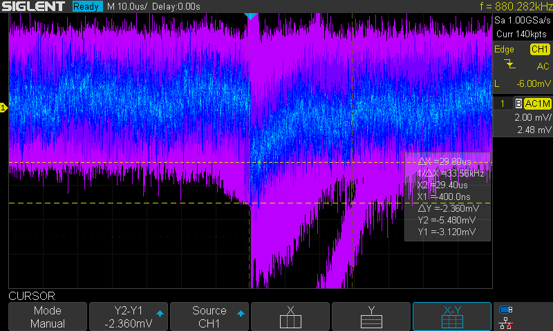
Whereas in the 10-diode scenario the circuit was unstable without the bootstrap. It started to generate regular spikes as a form of excitation. After applying the bootstrap, the preamplifier became stable again. I checked the stability twice and in each individually assembled prototype the situation was the same. Even increasing the input capacitance did little to reduce the spikes of excitation, not to mention that it drastically decreased sensitivity. After returning to the preset feedback capacitance of 0.47pF and mounting the bootstrapping JFET the circuit once again detected radiation pulses. The bootstrap has helped to handle the capacitance of the diodes so that the amplifier excitation criteria was not met. Examining the captured pulses, it is clearly visible that 10 diodes introduce greater noise. Distortions amplitude has increased and there are greater fluctuations in the noise baseline. Despite the increased noise the undisturbed pulse height (below noise floor) remained approximately the same as with one diode. I also noticed a tendency that greater energy pulses start to become visible after the bootstrap was applied. It speaks for the usefulness of it.
To sum it up, from the tests it can be seen that the bootstrapping circuit:
- Increases the sensitivity and stability of the preamplifier
- Alters the noise spectrum so that low frequencies become more exposed
- Can be applied even for low capacitance scenarios without signal degradation
Because of these advantages the bootstrapping circuit will be used in further detector development.
Feedback resistance impact on the amplitude and shape of the pulse
To understand how the feedback resistor influences the pulse, I performed a sweep of Rf values starting from 10k to 1Gig. The data gathered included: Vpp noise, pulse height below measured noise floor, pulse length. Most of these measurements were performed in display persist mode. After a while of collecting pulses or noise, the average (most repetitive) value was measured and saved. I am aware of the inaccuracies of this method, but in a random phenomenon like radiation this was the one I found at hand. For the tests the oscilloscope bandwidth was limited to 20MHz so that the pulses were visible more clearly. Response was measured with one diode and presets as mentioned before.
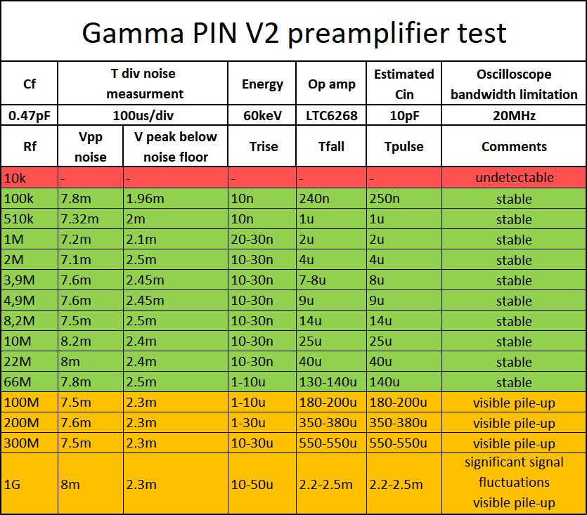
From the data gathered it is visible that above certain value the feedback resistor does not increase pulse height and signal to noise ratio remains approximately the same. What it does change is the pulse duration and length of the pulse tail. The pulses have a characteristic shape of a capacitor discharge curve with a steep charge moment. From this shape and the constant peak amplitude I assume that the transimpedance amplifier works in a different way than expected before.
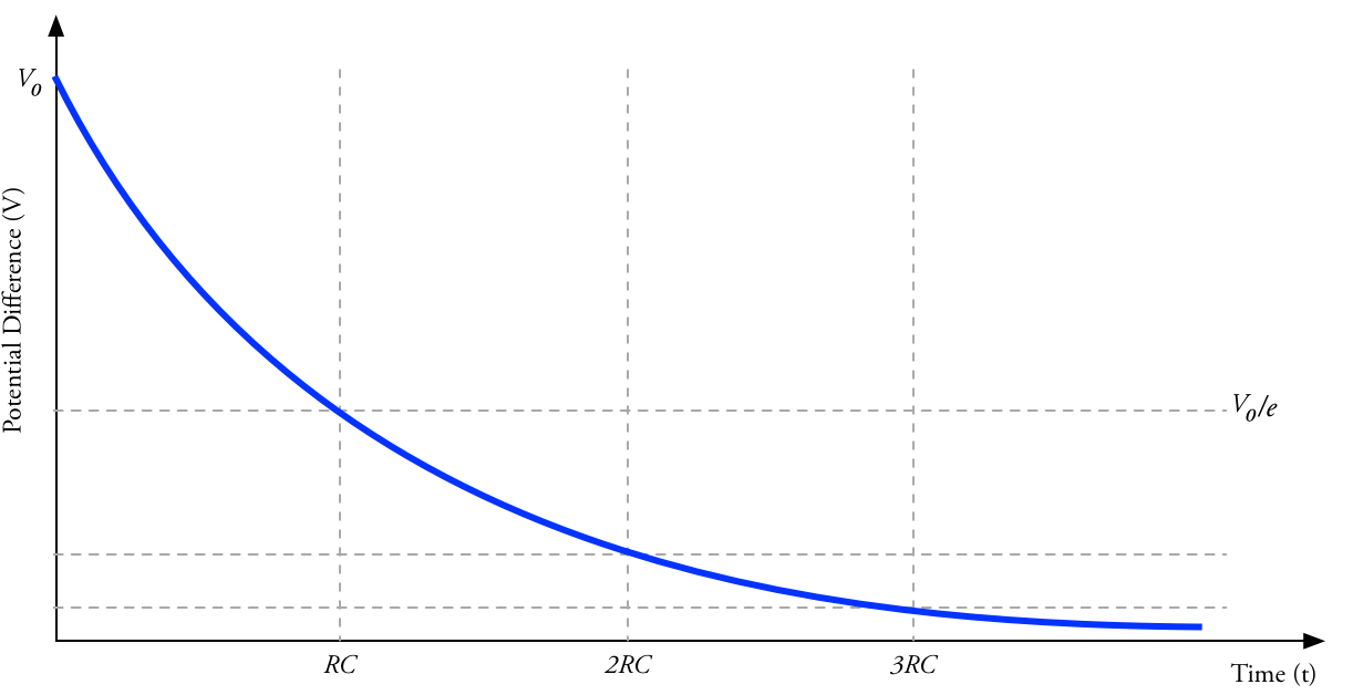
Due to huge feedback resistance values and capacitances connected to the op amp it works as an integrating amplifier. It is unexpected but yet very useful, because integration delivers the exact information about energy of a particle or photon. The charge injected and deposited from radiation is equal to the peak value of the pulse from the preamplifier. The detector behaves as a capacitor with random charge injections. To verify if the first stage of the detector follows the typical capacitor discharge curve, I created a graph. It shows linear dependence of the pulse length from the feedback resistance value. The measured values differed from the ones calculated from the estimated values. But after applying a RC multiplier the two series of values almost covered one another.
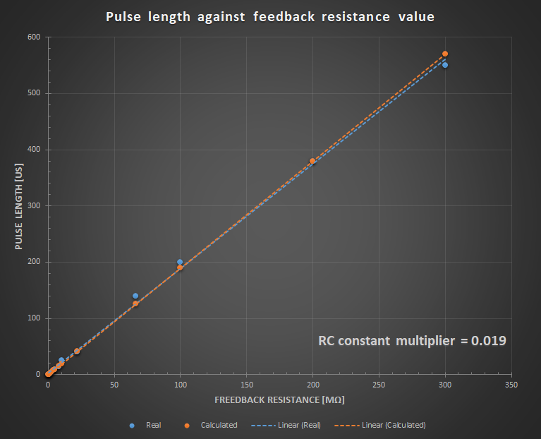
Having this graph, estimation of the pulse duration and the dead time of the detector will be easier.
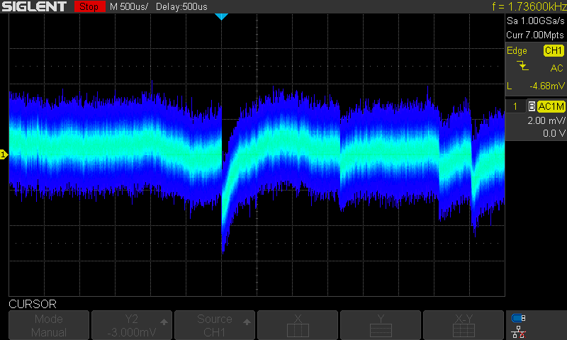
Pile-up effect
When the feedback resistance value was pretty enormous and thanks to it pulse, length was extended. I could observe pulse pile-up, which introduced misrepresentation of pulse amplitude. When baseline is shifted in some way the pulse readout becomes useless and the detector can only count them. To prevent this from happening feedback resistance has to be adjusted so that the dead time would not be too long to choke the detector neither too low to degrade the signal to noise ratio. In the oncoming third version of the detector this obstacle will be addressed with a proper baseline restorer solution and a rising slope detector.
Discussions
Become a Hackaday.io Member
Create an account to leave a comment. Already have an account? Log In.