 Just4Fun
* NOTE TO THE READER *: Due to a text size limitation of the Hackaday. io site a few chapters have been moved to "Log files". In this case you have just to click on the link of the chapter's title to open a new tab and read it.
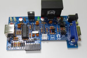
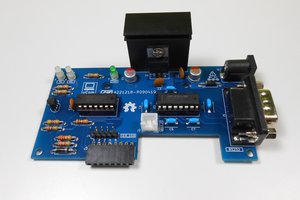
* * HARDWARE OVERVIEW * *
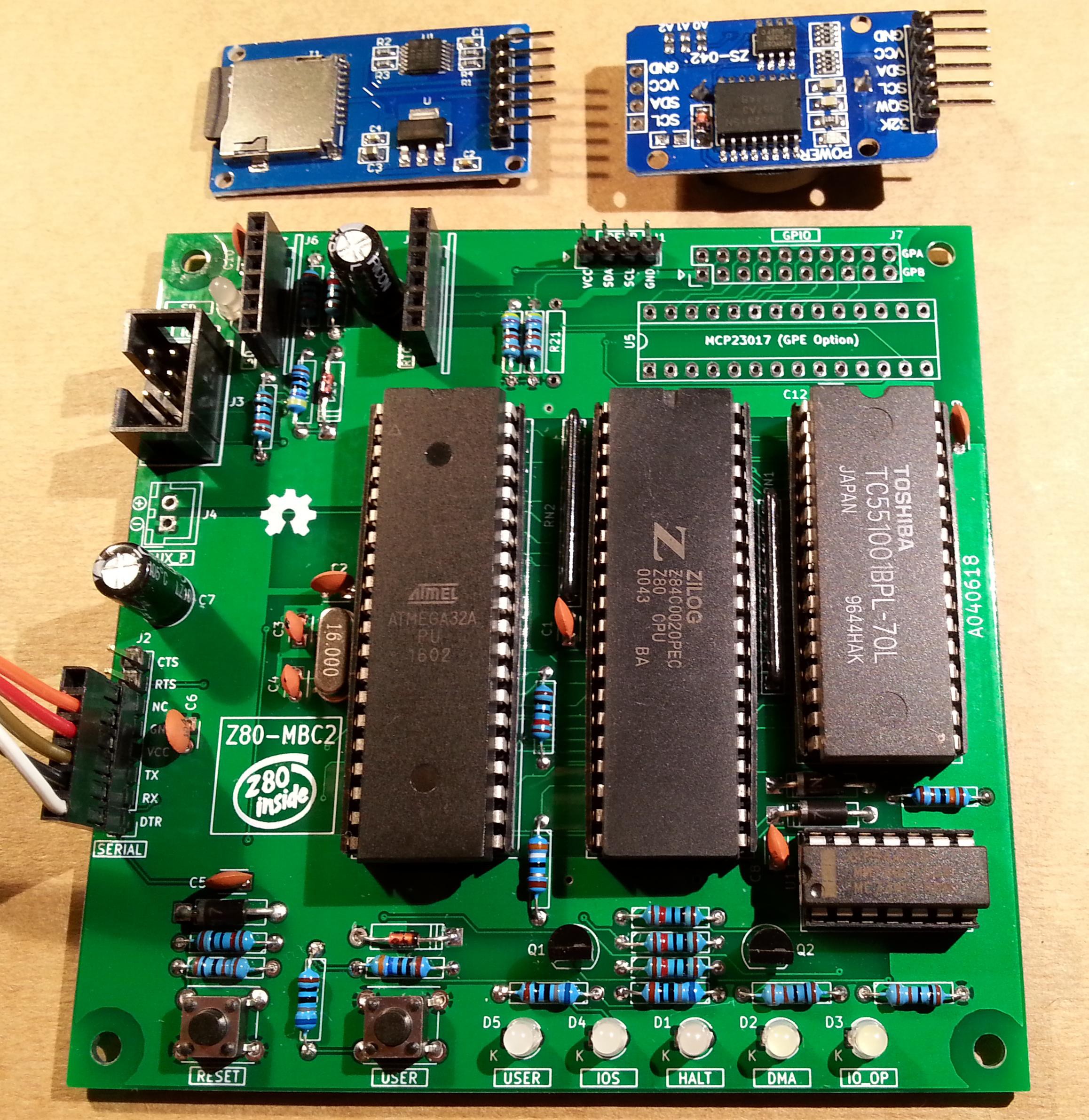
The needed ICs for the "base system" are:
- Z80 CPU CMOS (Z84C00) 8Mhz or greater
- Atmega32A
- TC551001-70 (128kB RAM)
- 74HC00
If you want the 16x GPIO expansion (GPE option) add a MCP23017 too.
The schematic and the BOM are attached in the Files section. The MCU Atmega32A is used as universal I/O subsystem, as Eeprom, and as reset and 4/8MHz clock generator for the Z80 CPU.
Inside the Atmega32A it is flashed an Arduino bootloader taken from here, and it is possible to use the Board Manager of the Arduino IDE to "import" it.
Flash the Arduino bootloader at first (with the method you prefer), next you can upload the IOS "sketch" (the I/O Subsystem that interacts with the Z80 bus and "virtualizes" the EEPROM and all the peripherals seen by the Z80 CPU) using Arduino IDE.
You can use the on board ICSP port J3 (also called ISP port) to write the bootloader, but remember to disconnect any other connector when using it. Also both SD and RTC modules (if present) must be removed from the board when the ICSP port is in use.
As clock source for the Z80 CPU it is used the 16MHz Atmega32A oscillator, so the "external 16MHZ osc." bootloader variant must be chosen when flashing the bootloader from the Arduino IDE!.
The 74HC00 is used as RS flipflop to stop the Z80 CPU during I/O operation, giving the needed time to the Atmega32A to interact with the Z80 bus, and as part of the MMU.
Note that only the CMOS version of the Z80 CPU can be used here. This because only CMOS version, under given condition that are respected in this schematic, has logical levels compatibles with Atmega32A and 74HC00.
NOTES ABOUT THE COMPONENTS
You should use a Z80 CMOS speed grade of at least 8MHz for full speed, but setting the clock speed at 4MHz you can use a 4MHz Z80 CMOS version too (or you can try to overclock it at 8MHz...). The 74HC00 can be substituted with a 74HCT00 if you already have one. The RAM chip TC551001-70 can be substituted with any suitable 128kB SRAM).
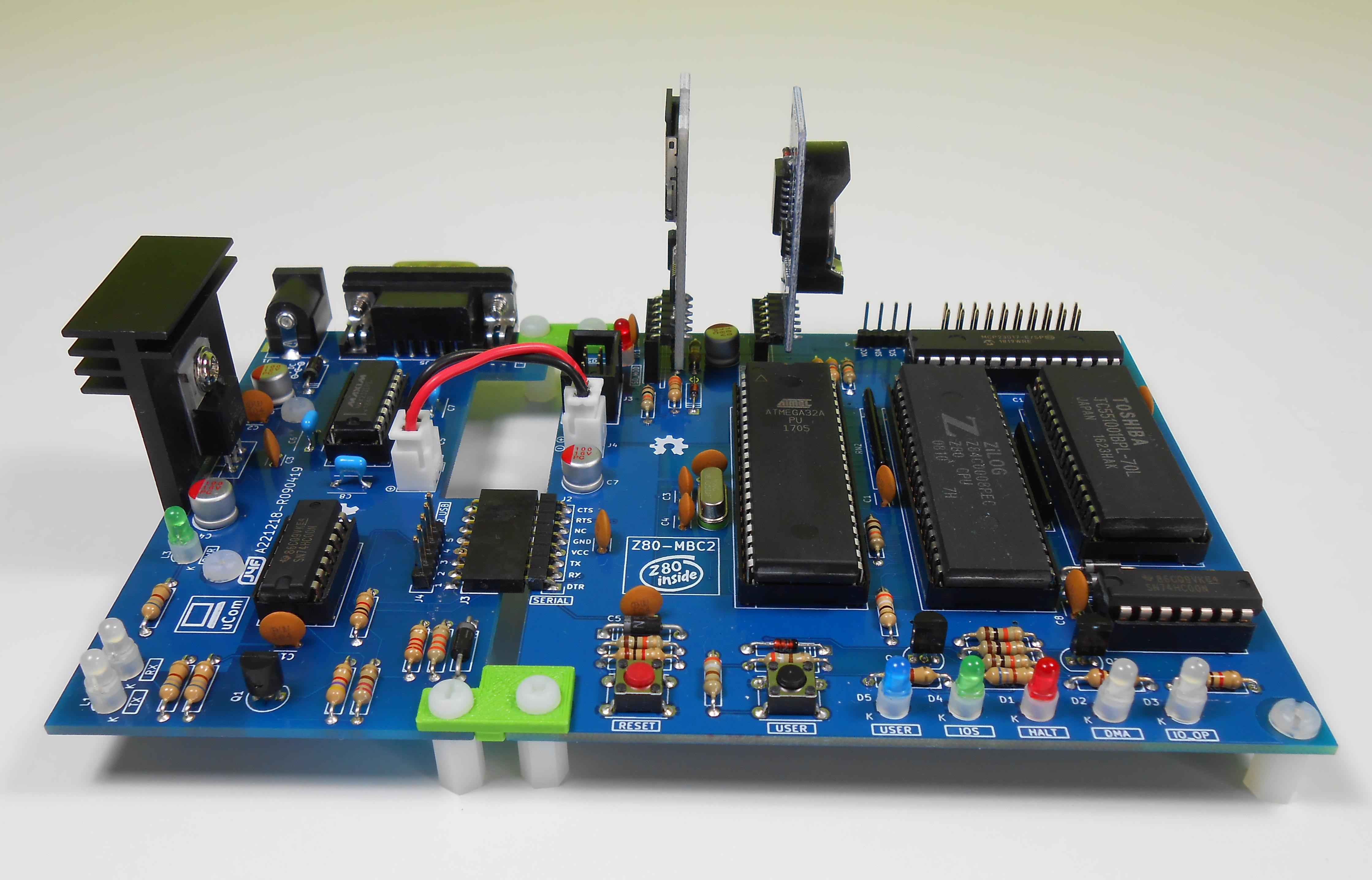
Please note that the USER led * must * be blue or white (or pink... I've some pink leds that seems to have a Vf like blue one. May be I'll do a board with them...) just to be sure that V(forward) is >= 2.7V (otherwise the USER key may not work as expected).
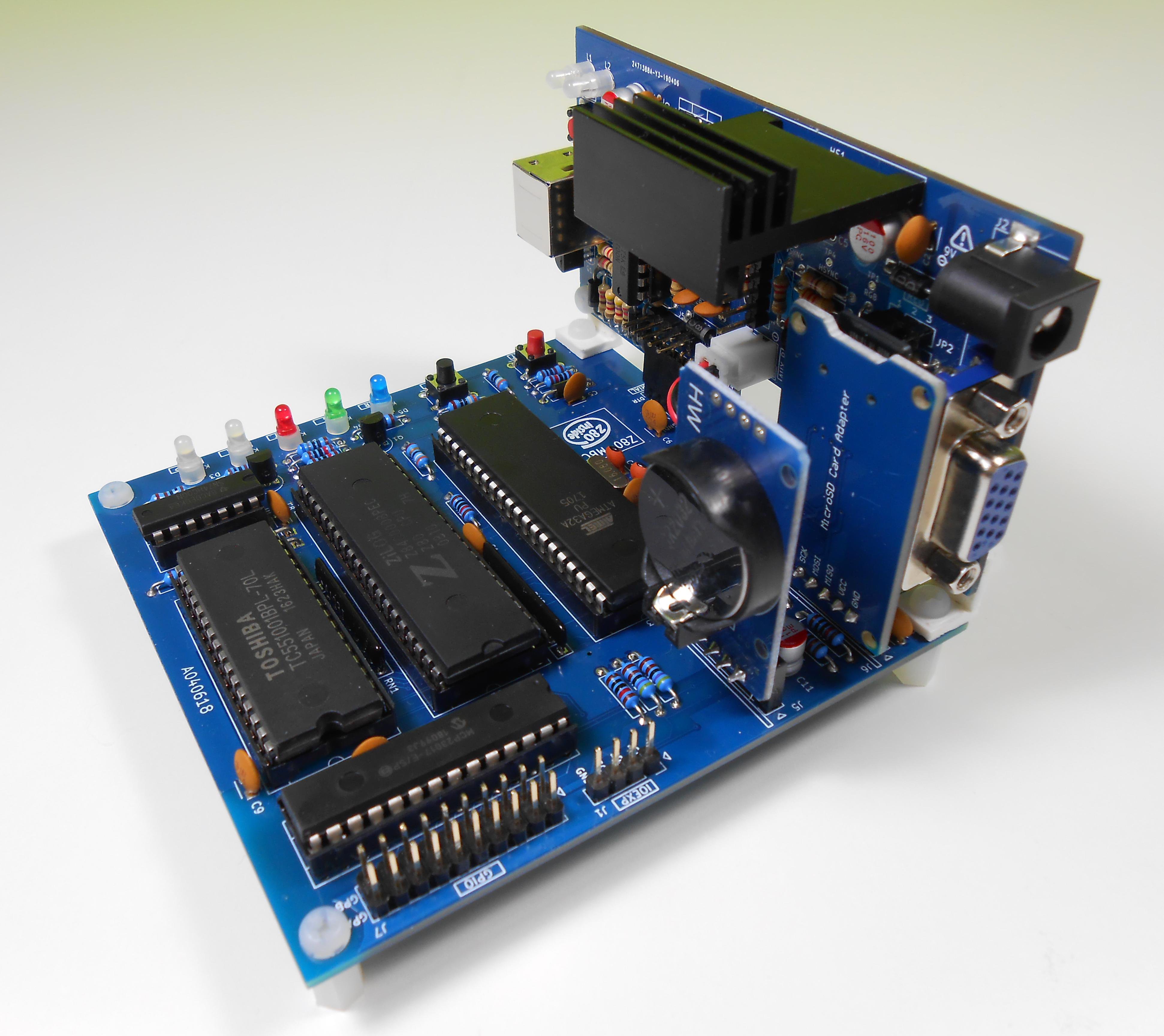
The J4 connector (AUX_P) is used as auxiliary power connector when an add-on board (uCom or uTerm) is connected.
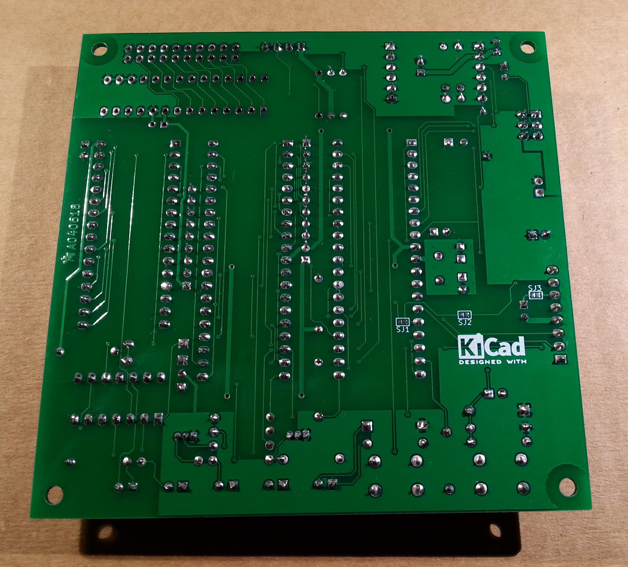
The three solder jumpers (SJ1-3) on the bottom side are not currently supported and must be left opened (as stated in the schematic).
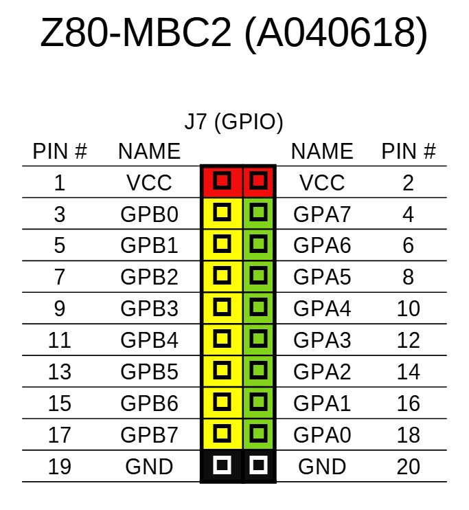
THE GPE OPTION (GPIO CONNECTOR)
It is possible to choose to populate on the PCB a GPIO port expander (U5) to add 16 bidirectional GPIO pins. The GPE option (see the schematic) can be used with the SPP Adapter board (see the paragraph: SPP (STANDARD PARALLEL PORT) ADAPTER BOARD).
The pinout of the GPIO (J7) connector is:
THE SERIAL PORT
The SERIAL port (J2, see schematic) can be connected with a TTL-RS232 adapter, or with a serial-USB adapter.
I've used a serial-USB adapter that acts also as power source for the Z80-MBC, and has the DTR signal for the "autoreset" driven from the Arduino IDE. For a terminal that has a serial TTL port no adapter is needed.
Of course to upload a "sketch" from Arduino IDE you need to use a serial-USB adapter connected to the SERIAL port.
Note that the RTS and CTS pins of the SERIAL port are not currently supported and must be left not connected (as the NC pin!).
The 3V3 pin of the serial-USB adapter must be left disconnected (if present).
You should use those Serial-USB adapters that have the DTR pin on the connector. It is suggested to have also the CTS/RTS signals available for future upgrades.
Please note that all the pin...
Read more »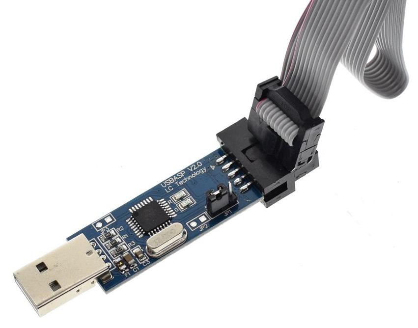
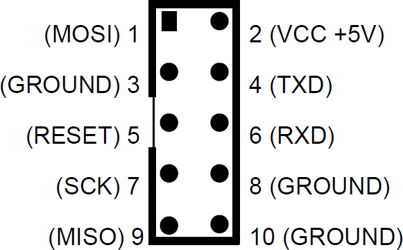
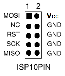
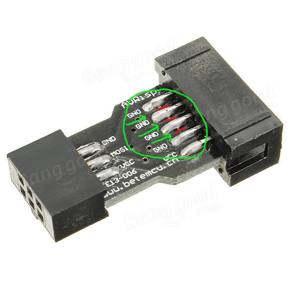
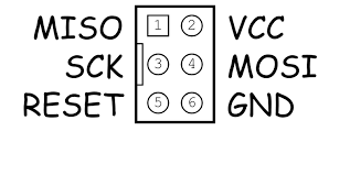 To avoid problems I suggest to use as GND pin 10 of the USBasp connector, and connect the other pins (VCC, MISO, MOSI,SCK, RST) accordingly.


I built a second system. It is up and running just fine with a HM628128ALP-7 SRAM as well. To test the board I booted CP/M and ran MBASIC. I opened the "Examples with Basic" on my PC, copied the USER LED BLINK example and pasted it into Tera Term at the MBASIC prompt. This is a very easy way to get a program into the system. Then I did SAVE "BLINK",A to put the app into the SD Card disk file. RUN executed the app and blinked the LED. All in all, it took about a minute the run the app to test the LED. Very nice!