 Just4Fun
* NOTE TO THE READER *: Due to a text size limitation of the Hackaday. io site a few chapters have been moved to "Log files". In this case you have just to click on the link of the chapter's title to open a new tab and read it.
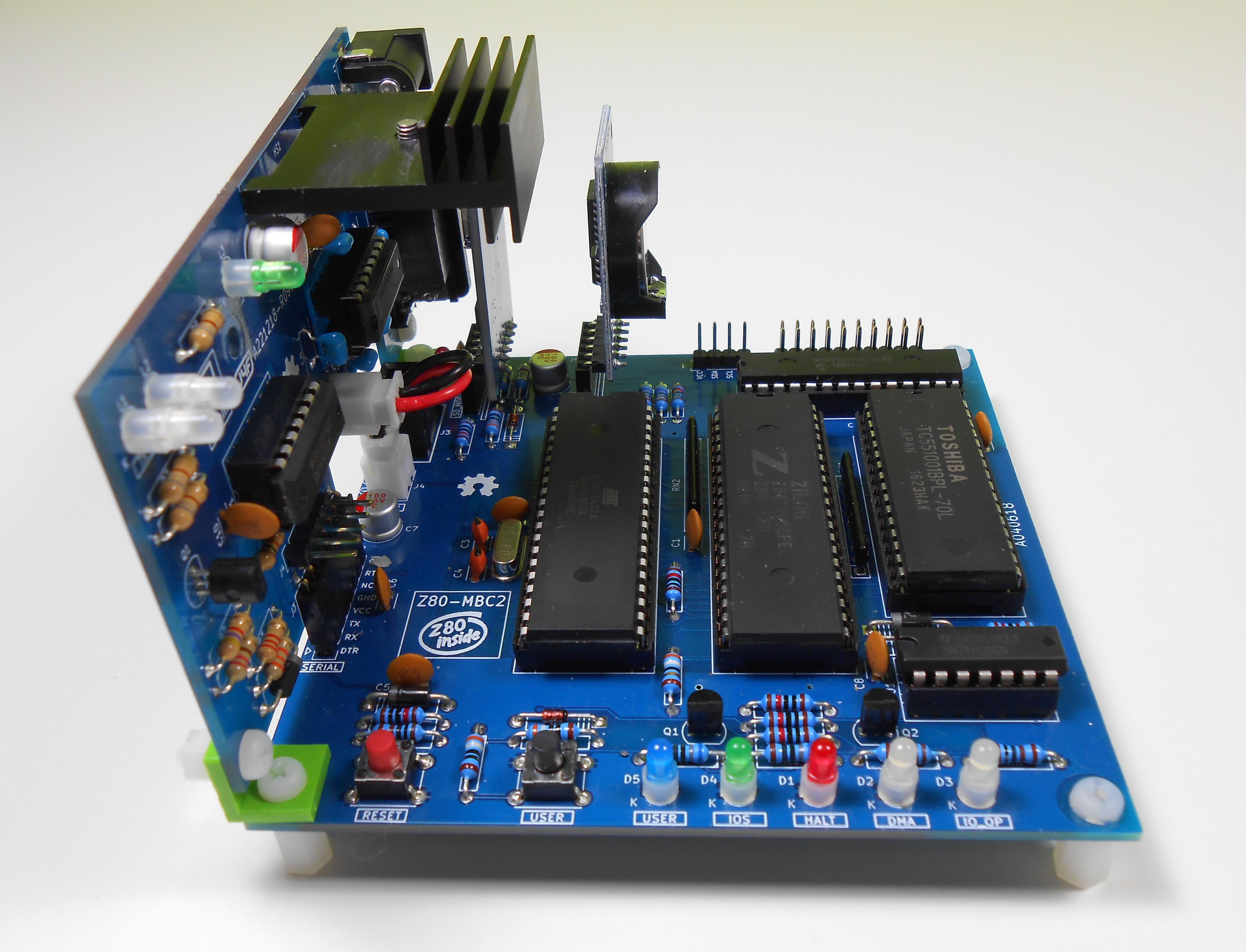
* * HARDWARE OVERVIEW * *
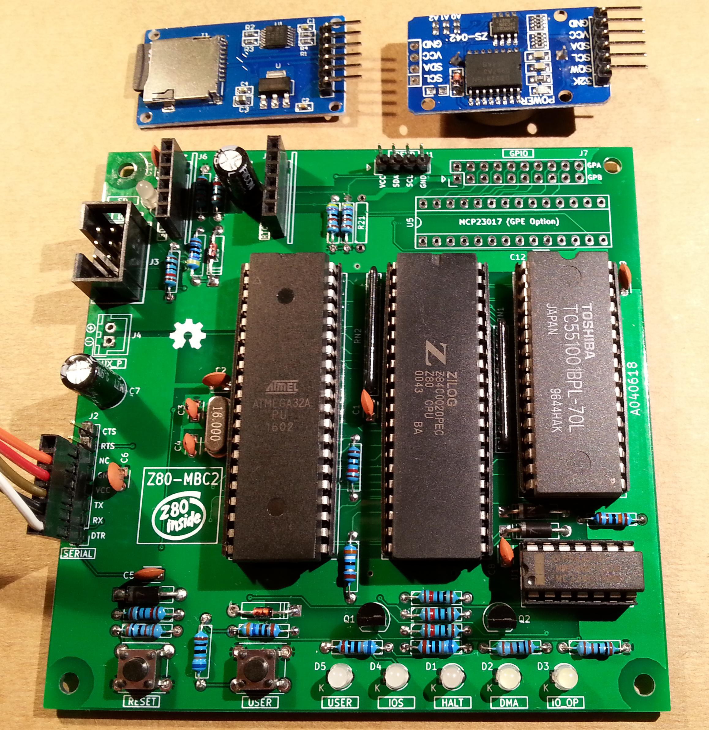
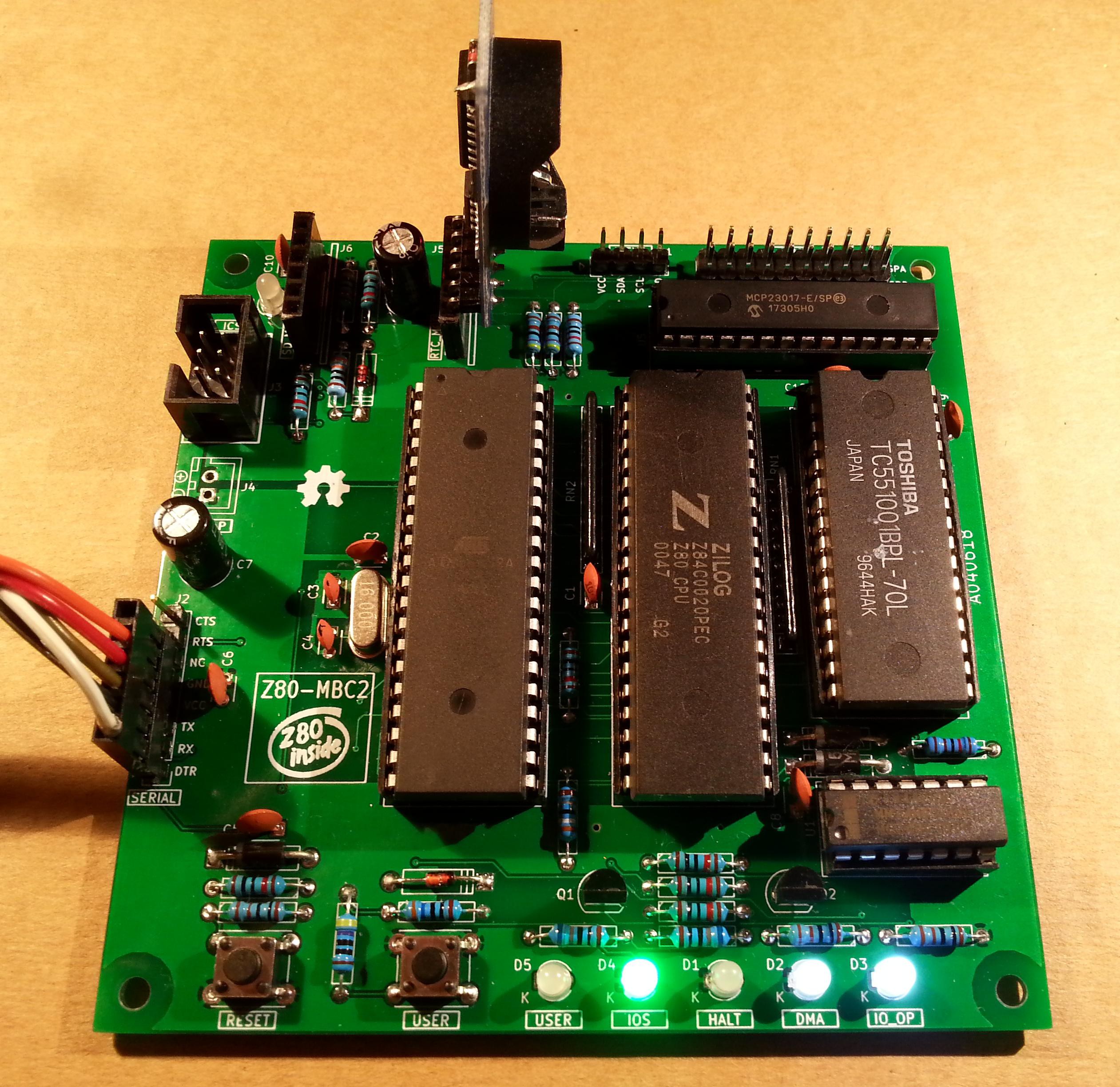
The needed ICs for the "base system" are:
- Z80 CPU CMOS (Z84C00) 8Mhz or greater
- Atmega32A
- TC551001-70 (128kB RAM)
- 74HC00
If you want the 16x GPIO expansion (GPE option) add a MCP23017 too.
The schematic and the BOM are attached in the Files section. The MCU Atmega32A is used as universal I/O subsystem, as Eeprom, and as reset and 4/8MHz clock generator for the Z80 CPU.
Inside the Atmega32A it is flashed an Arduino bootloader taken from here, and it is possible to use the Board Manager of the Arduino IDE to "import" it.
Flash the Arduino bootloader at first (with the method you prefer), next you can upload the IOS "sketch" (the I/O Subsystem that interacts with the Z80 bus and "virtualizes" the EEPROM and all the peripherals seen by the Z80 CPU) using Arduino IDE.
You can use the on board ICSP port J3 (also called ISP port) to write the bootloader, but remember to disconnect any other connector when using it. Also both SD and RTC modules (if present) must be removed from the board when the ICSP port is in use.
As clock source for the Z80 CPU it is used the 16MHz Atmega32A oscillator, so the "external 16MHZ osc." bootloader variant must be chosen when flashing the bootloader from the Arduino IDE!.
The 74HC00 is used as RS flipflop to stop the Z80 CPU during I/O operation, giving the needed time to the Atmega32A to interact with the Z80 bus, and as part of the MMU.
Note that only the CMOS version of the Z80 CPU can be used here. This because only CMOS version, under given condition that are respected in this schematic, has logical levels compatibles with Atmega32A and 74HC00.
NOTES ABOUT THE COMPONENTS
You should use a Z80 CMOS speed grade of at least 8MHz for full speed, but setting the clock speed at 4MHz you can use a 4MHz Z80 CMOS version too (or you can try to overclock it at 8MHz...). The 74HC00 can be substituted with a 74HCT00 if you already have one. The RAM chip TC551001-70 can be substituted with any suitable 128kB SRAM).
Please note that the USER led * must * be blue or white (or pink... I've some pink leds that seems to have a Vf like blue one. May be I'll do a board with them...) just to be sure that V(forward) is >= 2.7V (otherwise the USER key may not work as expected).
The J4 connector (AUX_P) is used as auxiliary power connector when an add-on board (uCom or uTerm) is connected.
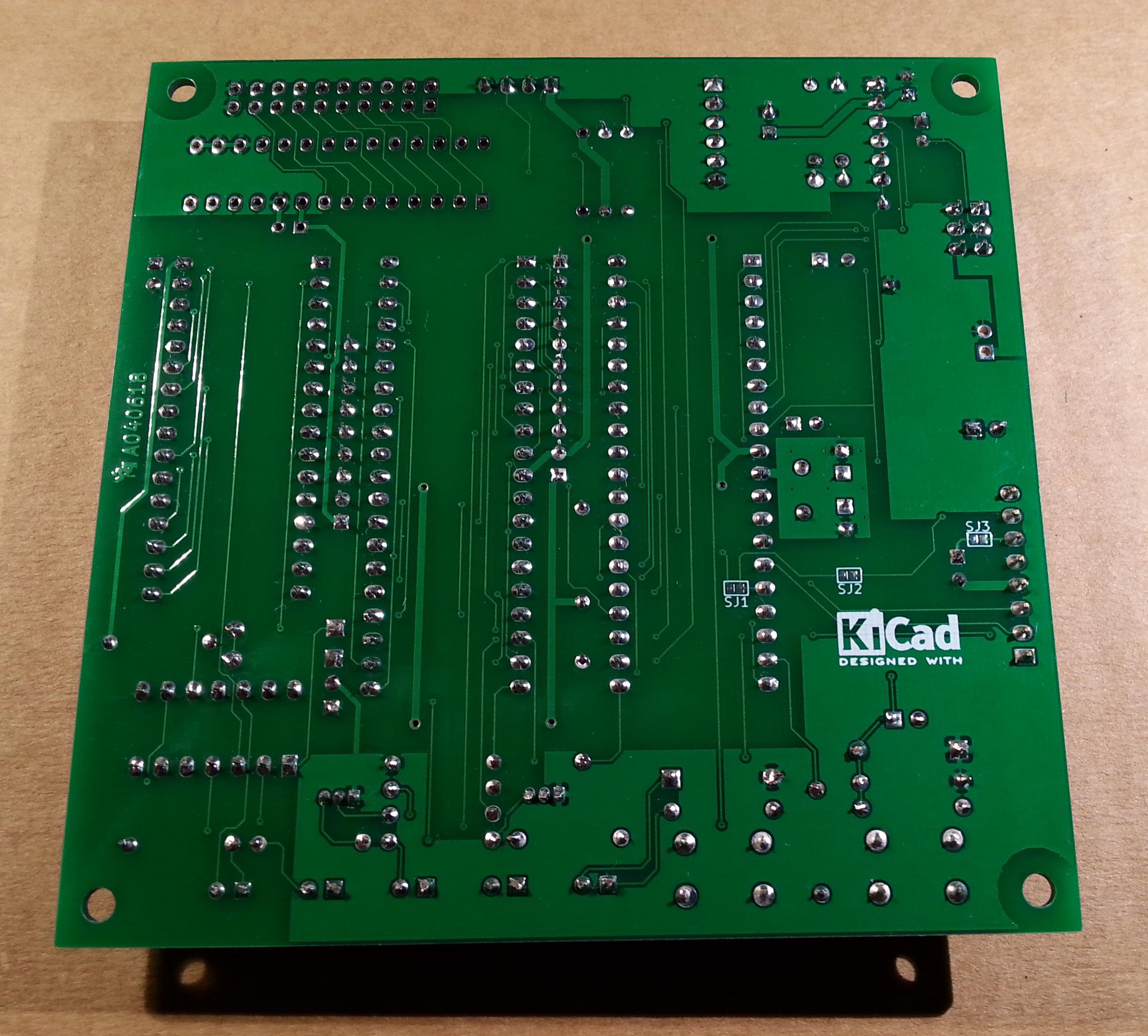
The three solder jumpers (SJ1-3) on the bottom side are not currently supported and must be left opened (as stated in the schematic).
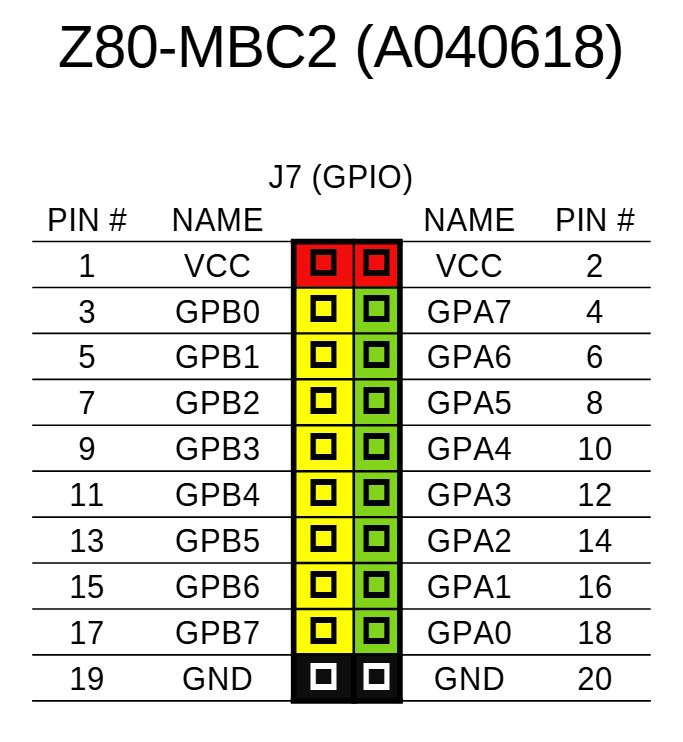
THE GPE OPTION (GPIO CONNECTOR)
It is possible to choose to populate on the PCB a GPIO port expander (U5) to add 16 bidirectional GPIO pins. The GPE option (see the schematic) can be used with the SPP Adapter board (see the paragraph: SPP (STANDARD PARALLEL PORT) ADAPTER BOARD).
The pinout of the GPIO (J7) connector is:
THE SERIAL PORT
The SERIAL port (J2, see schematic) can be connected with a TTL-RS232 adapter, or with a serial-USB adapter.
I've used a serial-USB adapter that acts also as power source for the Z80-MBC, and has the DTR signal for the "autoreset" driven from the Arduino IDE. For a terminal that has a serial TTL port no adapter is needed.
Of course to upload a "sketch" from Arduino IDE you need to use a serial-USB adapter connected to the SERIAL port.
Note that the RTS and CTS pins of the SERIAL port are not currently supported and must be left not connected (as the NC pin!).
The 3V3 pin of the serial-USB adapter must be left disconnected (if present).
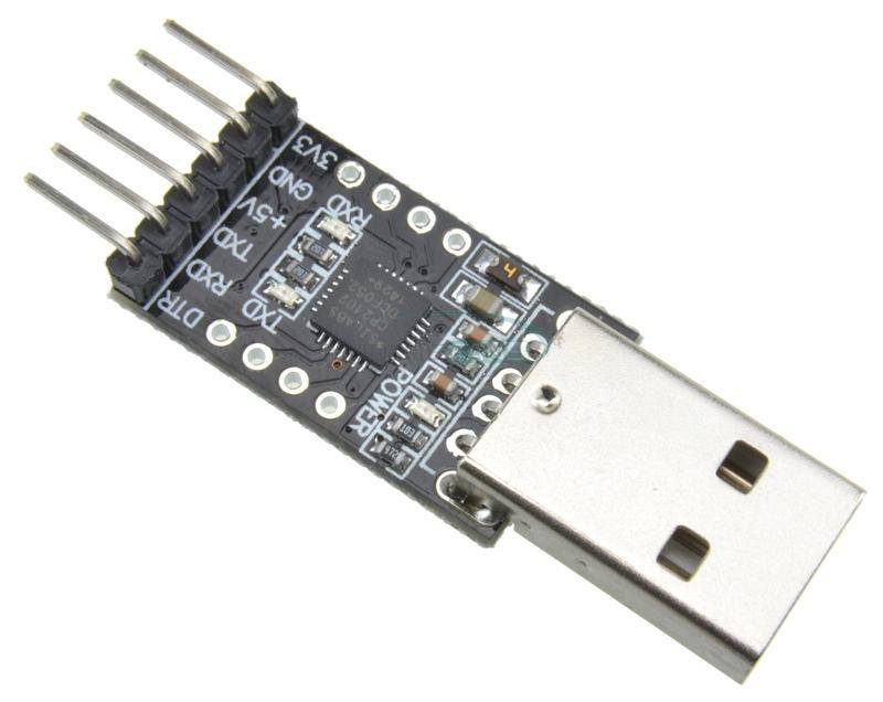
You should use those Serial-USB adapters that have the DTR pin on the connector. It is suggested to have also the CTS/RTS signals available for future upgrades.
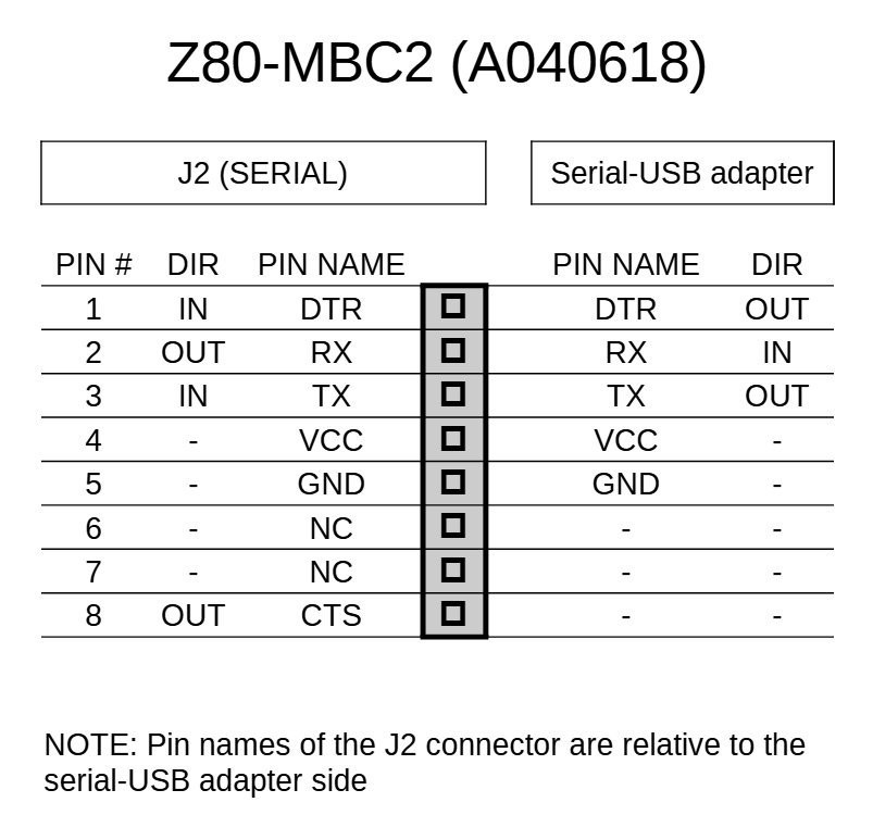
Please note that all the pin names of J2 on the PCB are referred to the serial-USB adapter, so all the signals as TX and RX are relative to the serial-USB adapter side (in other words TX and RX are already "inverted". See the schematic).
Here a suggested serial-USB adapter based on a CP2102 (very common on ebay):

In the following table there is the SERIAL (J2) connector pinout and how connect it to the serial-USB adapter. Please note that in this configuration the Z80-MBC2 board must be exclusively powered from the serial-USB adapter itself:
THE OPTIONAL RTC MODULE
The RTC is a common module based on a DS3231 RTC like this one:
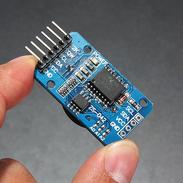
This cheap modules have a trickle charging circuit that may cause the "explosion" of the battery if you use a standard CR2032 cell. More, it can damage also a rechargeable LIR2032 cell. For more information and how to fix it see here.
The RTC module has it's own pullup resistors on SDA and SCL. Because the value is 4k7 (the same value used inside the Z80-MBC2 board), the resulting value will be:
4k7 // 4k7 = 2k3
Because this value is fine there is no need to take away the pullup on the RTC module.
Pay attention on how and where you plug the module in (the only right connector for it is J5 marked as RTC_MOD). If you plug it in the wrong connector or in the wrong way it is possible cause permanent damages to both the module and the Z80-MBC2 board! So plug it as shown in the photos (here a board with the GPE option installed):

THE OPTIONAL SD MODULE
The optional SD module is used as HD emulation. The module is a common 6 pins microSD module that can be easily found on ebay:
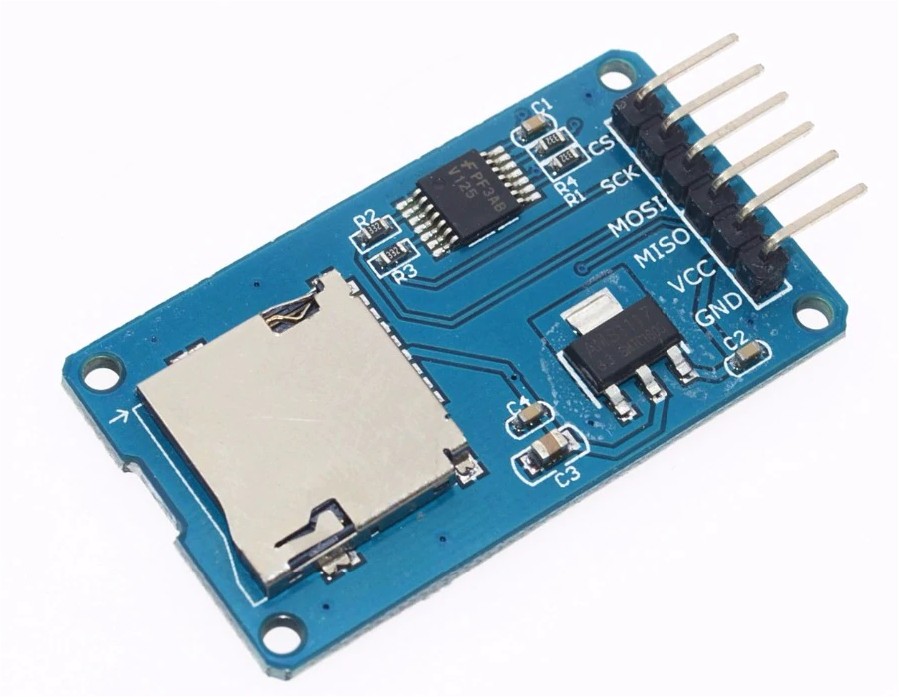
Pay attention on how and where you plug the module in (the only right connector for it is J6 marked as SD-MOD). If you plug it in the wrong connector or in the wrong way it is possible cause permanent damages to both the module and the Z80-MBC2 board!
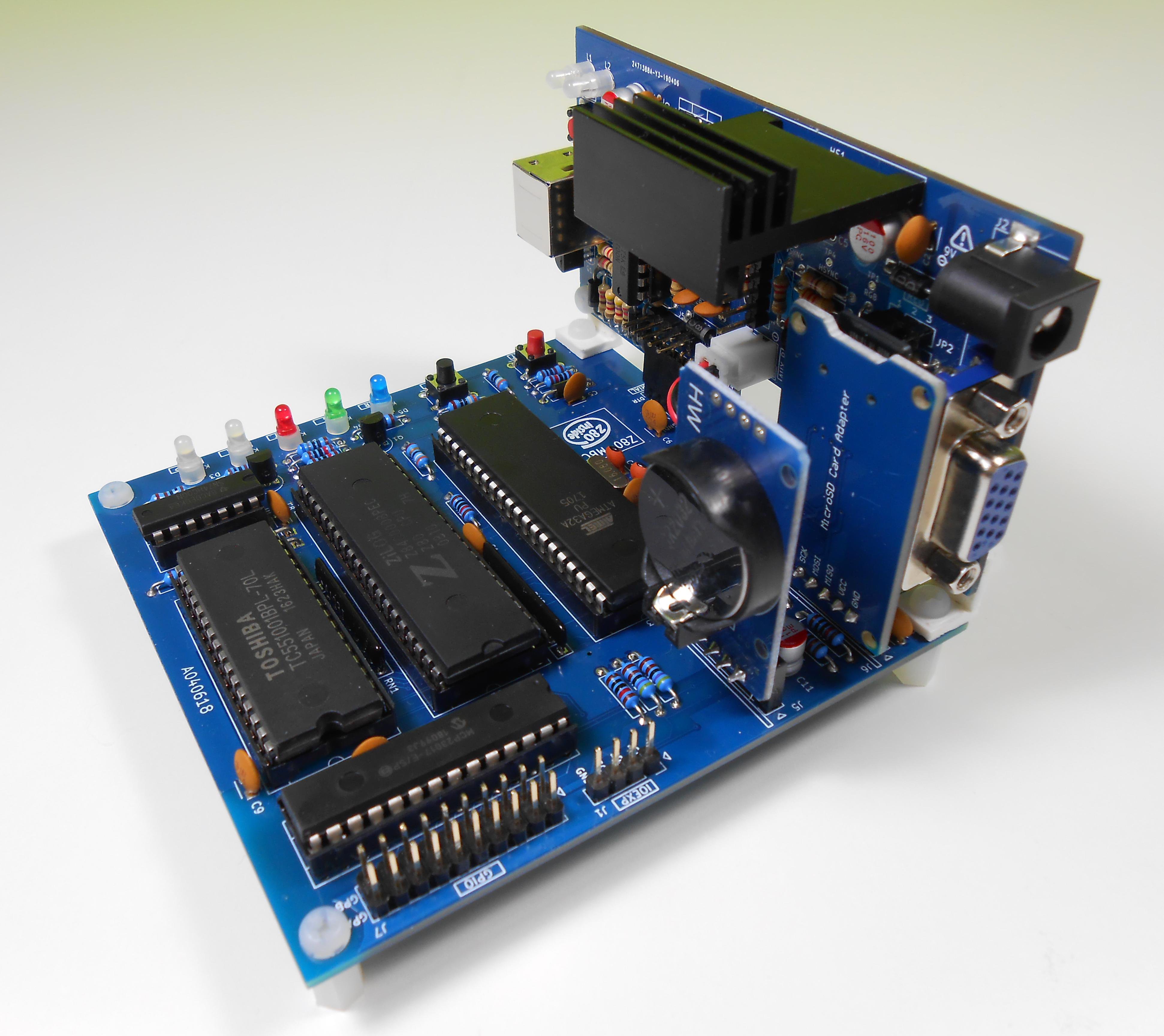
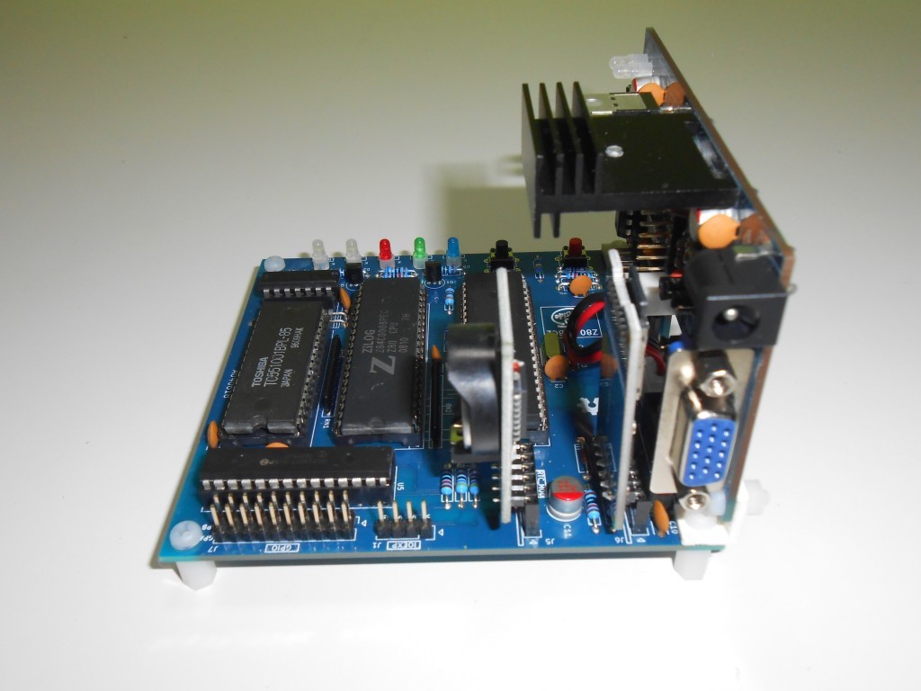
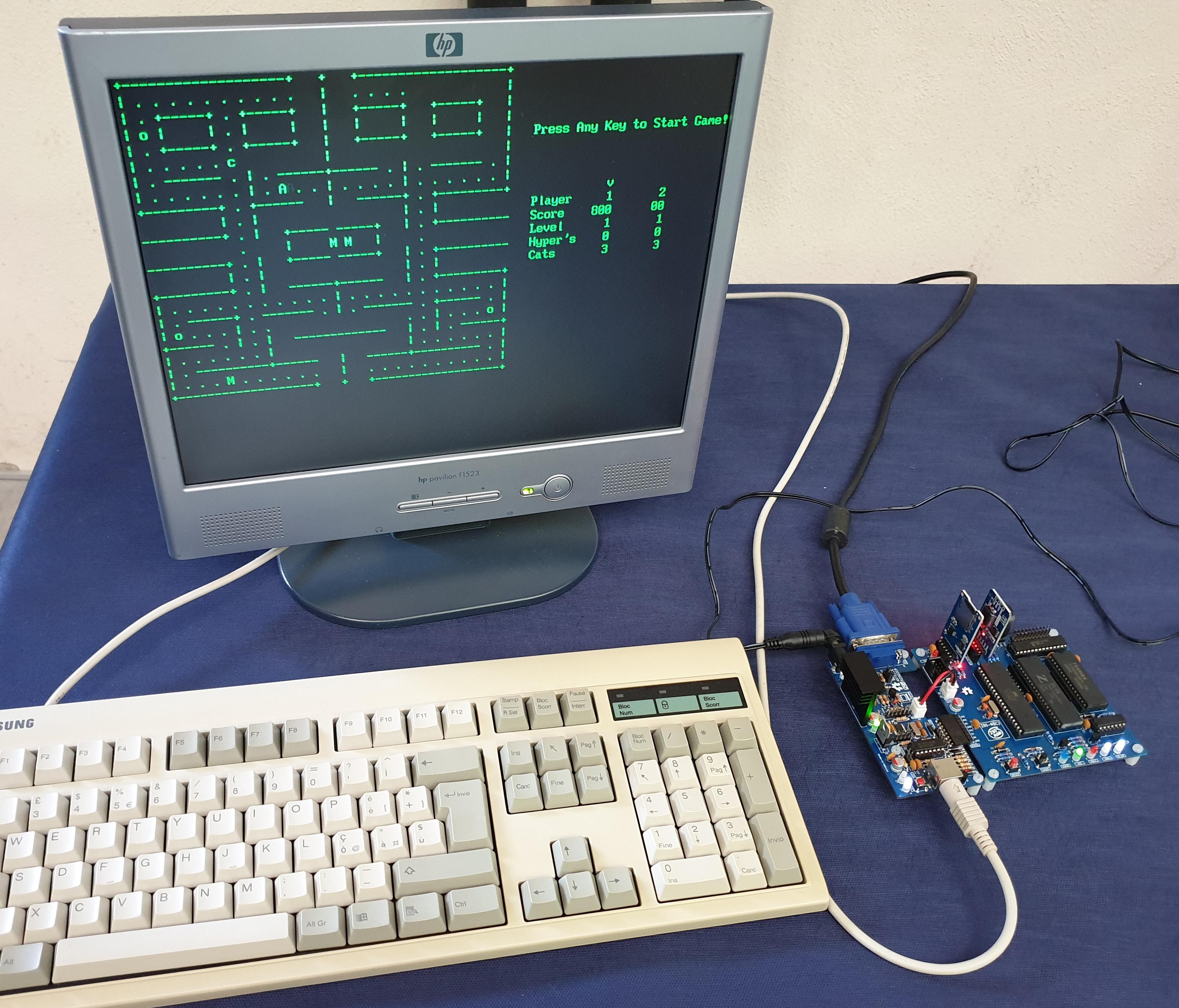
* * uTERM, VT100-LIKE TERMINAL FOR THE Z80-MBC2 * *
uTerm (micro-Term) is a VT100-like terminal for the Z80-MBC2. It has a VGA out and PS/2 keyboard connector, a power supply for the Z80-MBC2 and a "transparent" serial-USB port.
uTerm can be mounted horizontally or vertically to the Z80-MBC2.
With the uTerm the Z80-MBC2 becomes an "autonomous" computer:


All the details on the uTerm are here.
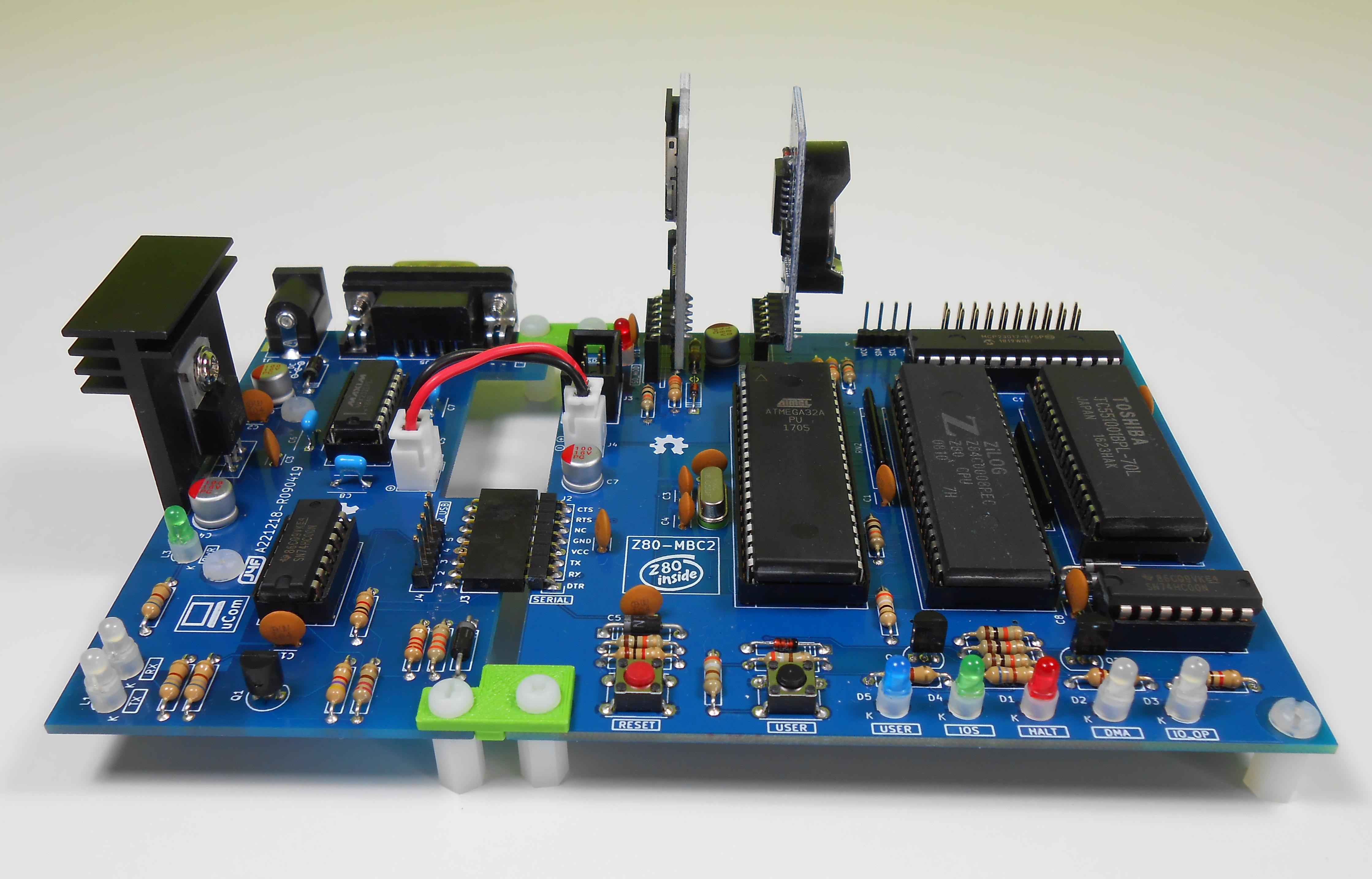
* * uCOM, RS232 FOR THE Z80-MBC2 * *
uCom (micro-Com) is a RS232 adapter for the Z80-MBC2. It has a power supply for the Z80-MBC2 and a "transparent" serial-USB port.
uCom can be mounted horizontally or vertically to the Z80-MBC2:


With the uCom the Z80-MBC2 can be used with a "vintage" RS232 terminal:
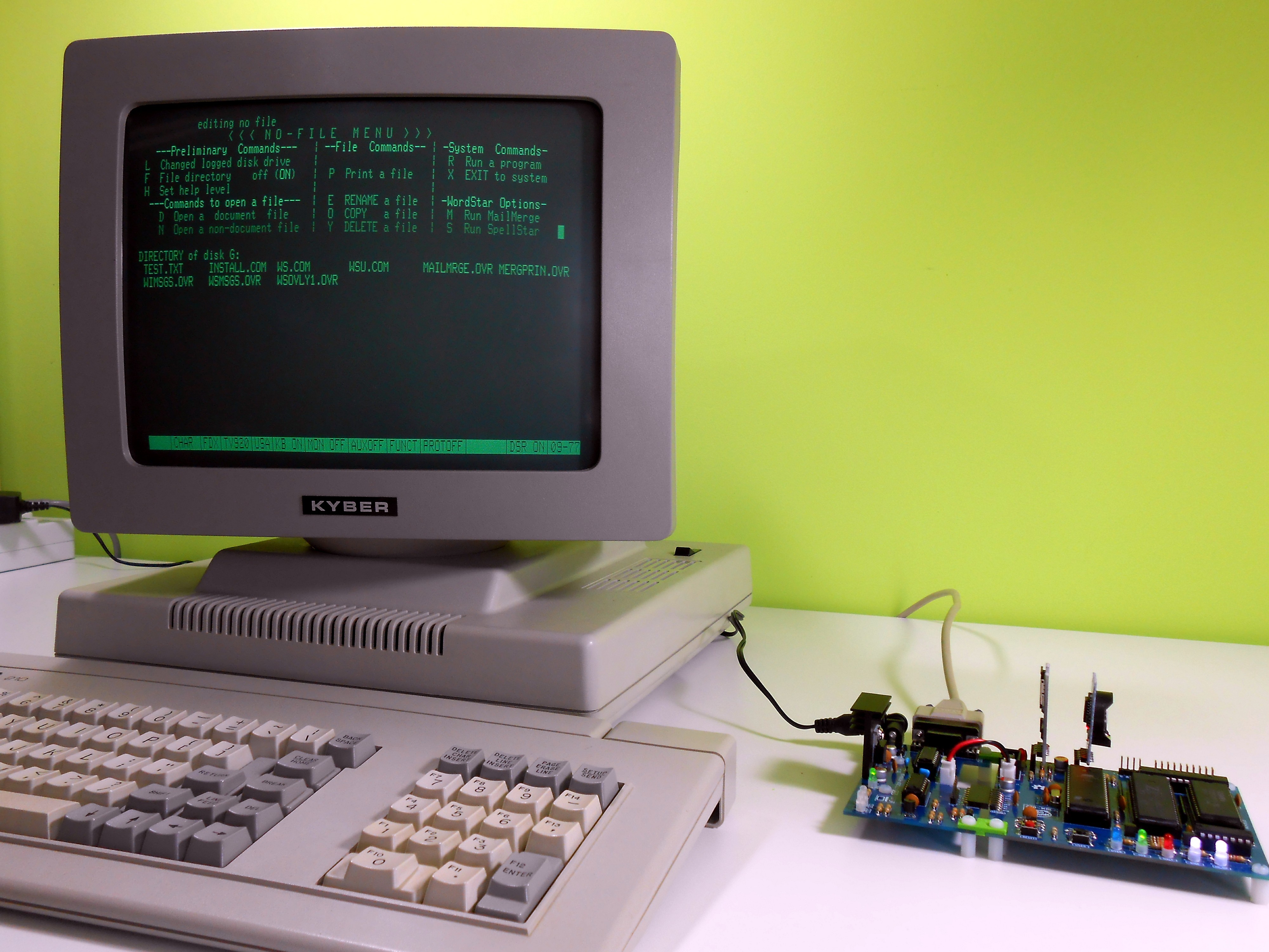
All the details on the uCom are here.
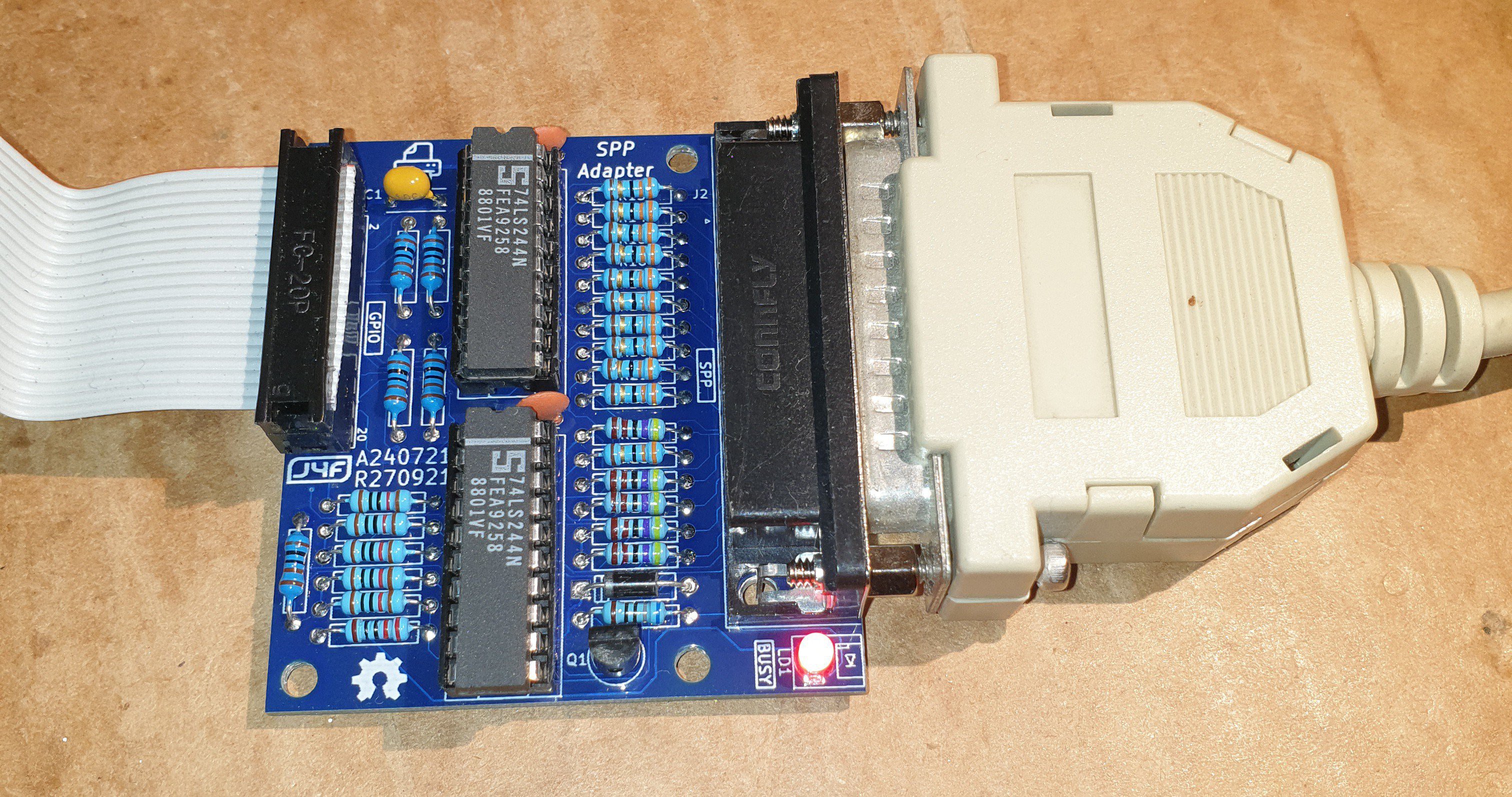
* * SPP (STANDARD PARALLEL PORT) ADAPTER BOARD * *
The Standard Parallel Port (SPP) Adapter board allows to use the GPIO port of the Z80-MBC2 as a standard printer parallel port.
In this way you can use a legacy parallel (Centronics) printer.
To connect the SPP Adapter board to the GPIO connector of the Z80-MBC2 board you need a 10cm long 20 wires flat cable terminated with an IDC connector at both sides (pay attention to connect the cable in the right way on both sides, so the pin 1 on the Z80-MBC2 GPIO connector corresponds to the pin 1 on the SPP Adapter board GPIO connector).
Please note that you have to power off the Z80-MBC2 board before connecting or disconnecting the SPP Adapter board to it.
NOTE: before using the SPP Adapter board (A240721-R270921, the same board used with the 68K-MBC) you have to update both the IOS firmware and the SD image to the latest available version (see the FILES section).
In the following image the SPP Adapter board with the flat cable (connected to the GPIO connector of the Z80-MBC2) and with the printer cable:
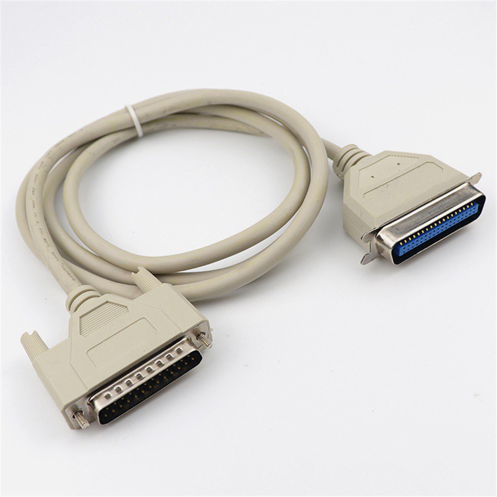
The cable to use for the printer is the common parallel printer cable, with a DB-25 connector at one side and a Centronics connector at the other:
SPP: HOW TO BUILD IT
In the FILES section you can find a zip file with all the documentation needed to build the SPP Adapter board, including the Gerber files for the PCB production.
SPP: HOW TO USE THE SPP CP/M UTILITY
To enable the SPP Adapter board under CP/M 2.2 and CP/M3 (banked) I've added on the drive A: the custom utility SPP.BAS.
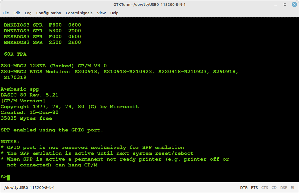
You have to execute the SPP utility with the command MBASIC SPP to enable the SPP Adapter board and "link" to it the LPT: CP/M device inside CP/M. After the execution of the SPP utility the GPIO port will be linked and reserved (the "normal" GPIO opcodes/functions inside IOS will be disabled) to the SPP parallel port emulation until a system reset or reboot:
NOTE: the SPP Adapter board is currently supported under CP/M 2.2 and CP/M 3 (banked) only.
SPP: WHERE TO GET A PCB
I've prepared an "easy" link to get a small lot (5 pcs minimum) of PCB of the SPP Adapter. The link is this one.
SPP: HOW TO GET A KIT OR AN ASSEMBLED UNIT
If you are looking for a SPP Adapter board kit with all the needed parts or an assembled unit ready to use now there is a professional seller that can sell both and ship worldwide.
The link to the seller is this one.
* * SOFTWARE OVERVIEW * *
The MCU Atmega32A is used as universal I/O subsystem, as Eeprom, and as reset and clock generator for the Z80 CPU.
The software running into the Atmega32A is the IOS (Input Output Subsystem) written using the Arduino IDE environment.
The IOS allows to interface the Atmega32A directly with the CPU system bus, emulating the needed I/O chips during the I/O read, I/O write and IRQ acknowledge CPU bus cycles (see the Z80 datasheet).
Furthermore, the IOS loads the RAM during the boot phase, "feeding" the CPU with the necessary instructions.
It is possible to choose between two different "flavors" of IOS: IOS and IOS LITE:
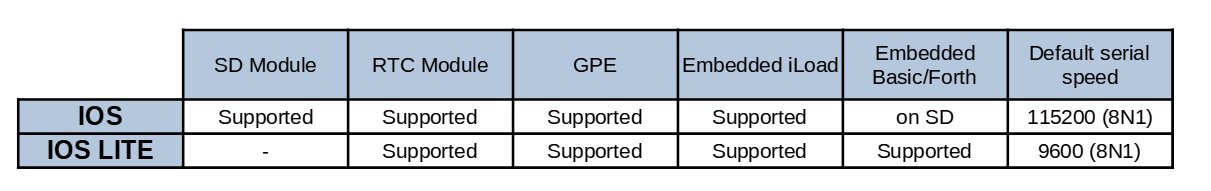
IOS LITE is more intended for testing the board for the base functions (it doesn't support the SD module, so only iLoad, the embedded stand-alone Basic and the embedded stand-alone Forth can be used). For normal use the standard IOS is the one to flash.
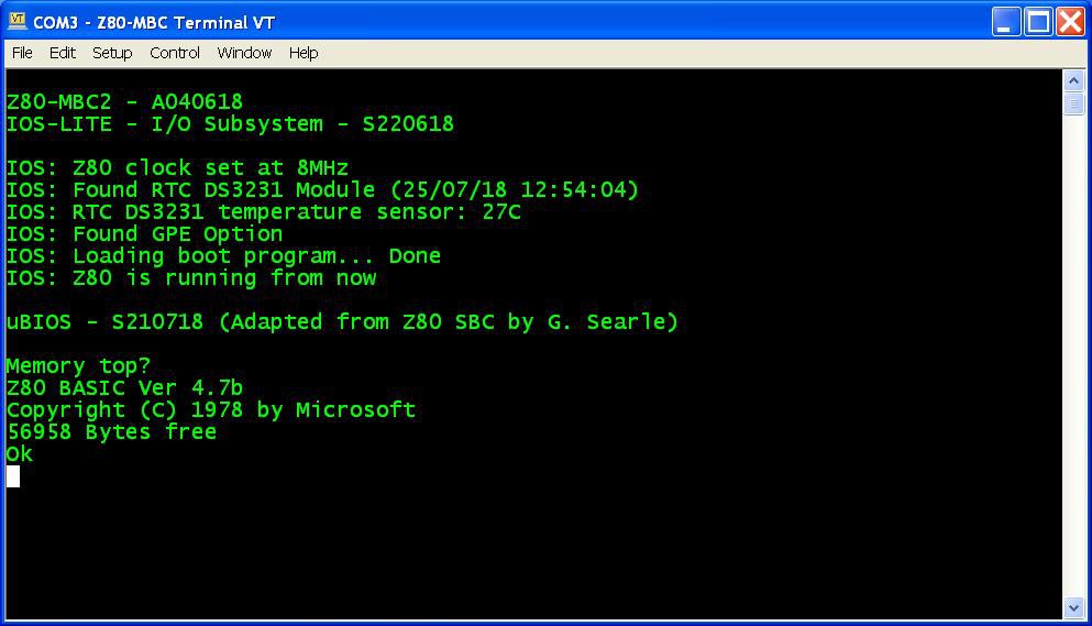
I've "ported" the stand-alone Basic interpreter to the Z80-MBC2 using the sources provided in the great Grant Searle site , after the needed modification due the different HW design (in the Grant's site is requested an acknowledgement to his site to use this source, so I did and I have also emailed to him about this thing).
The resulting ROM image is stored inside the Atmega32A (only for IOS-LITE) and loaded in the TC551001 RAM by the Atmega32A during the system boot. The original manual of this Basic interpreter is here.
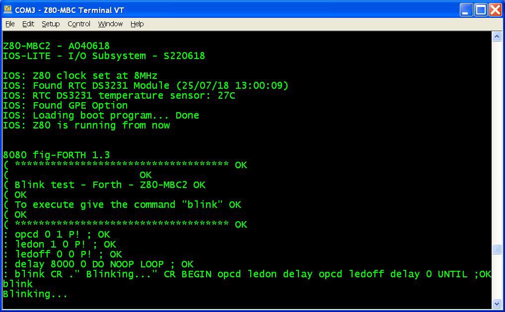
The Forth stand-alone interpreter is a modified version (for the Z80-MBC2) of the one provided by Bill Westfield for the Z80-MBC.
HOW FLASH THE BOOTLOADER FROM ARDUINO IDE (LINUX)
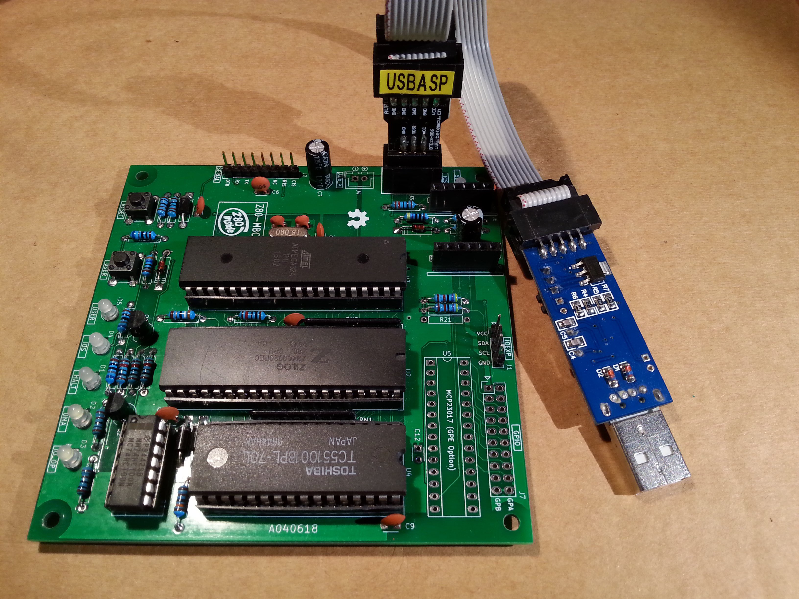
A cheap and easy way to burn the Arduino bootloader is to use an USBasp programmer that is commonly available:
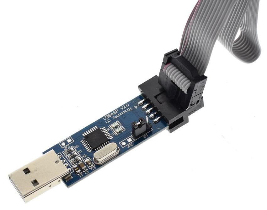
The USBasp is also capable to give the power to the "target" using the VCC pin, but remember to check that the JP1 jumper is set to provide 5V to the target (as shown in the photo).
Please note that the pinout of the USBasp is a little different from the "standard" ICSP (os ISP) pinout:
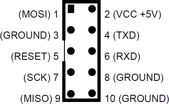
In the previous picture it is possible see that pins 4 (TXD) and 6 (RXD) are not at GND as expected by the standard ICSP port, and pin 3 is not NC.
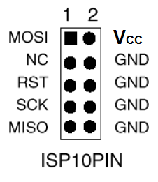
See the following picture showing the standard 10 pin ICSP pinout:
 So you must consider this when connecting the USBasp to the 6 pins ICSP port (J3) on the Z80-MBC2 (see the schematic):
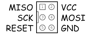 To avoid problems I suggest to use as GND pin 10 of the USBasp connector, and connect the other pins (VCC, MISO, MOSI,SCK, RST) accordingly.
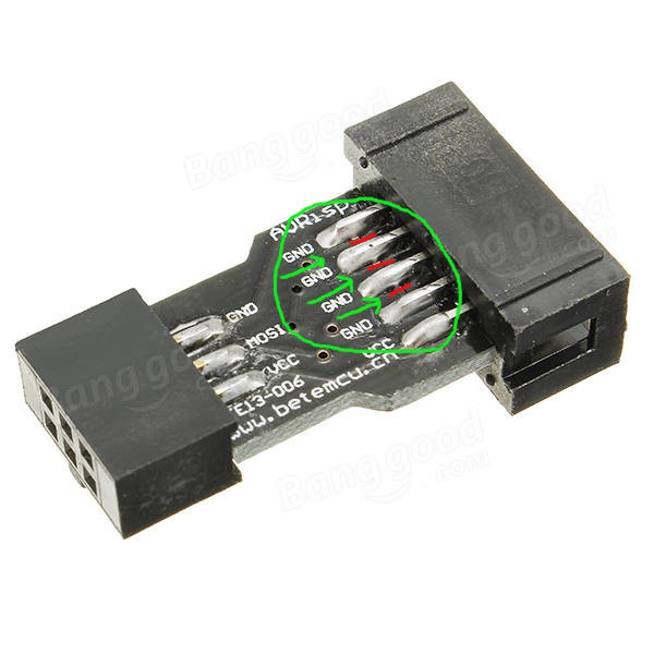
An handy way to connect the USBasp to the 6 pin ICSP port (J3) of the Z80-MBC2 could be to use a commonly available "10pin to 6pin" adapter like this:
To avoid problems I suggest to use as GND pin 10 of the USBasp connector, and connect the other pins (VCC, MISO, MOSI,SCK, RST) accordingly.
An handy way to connect the USBasp to the 6 pin ICSP port (J3) of the Z80-MBC2 could be to use a commonly available "10pin to 6pin" adapter like this:
 but I suggest not to use it "as is" because its internal connections are done for a "standard" ICSP port, and we have seen that the USBasp connector differs from the standard one.
The schematic of the adapter shows that isn't compatible "as is" with the UABasp connector:
but I suggest not to use it "as is" because its internal connections are done for a "standard" ICSP port, and we have seen that the USBasp connector differs from the standard one.
The schematic of the adapter shows that isn't compatible "as is" with the UABasp connector:

To use it is a good idea isolate the pins 4, 5 and 6 cutting the trace on the PCB of the adapter that connects those pins together, and then check with a tester. In the following photo are shown the three cuts (thin red lines inside the green "circle") to do:
To easily burn the bootloader from Arduino IDE follow these "quick and dirty" steps (tested on a linux Mint OS with Arduino IDE 1.8.19):
STEP 1: Connect the 10 pins connector of the USBasp programmer to the 6 pins ICSP port (J3) of the Z80-MBC2 (using wires or a modified adapter as discussed before);
STEP 2: Verify carefully that any other connector of the Z80-MBC2 is not used, and verify that both the SD and RTC modules (if present) are removed from the board;.
STEP 3: Only at this point connect the USB side of the USBasp programmer to an USB port of your workstation;
STEP 4: Open a "terminal" window on your workstation and go to the directory where there are the Arduino IDE executables, and get the root privileges with the command:
sudo su
then run the Arduino IDE with the command:
./arduino
STEP 5: Because Arduino IDE is running as the root user it is necessary re-install the "core" for the Atmega32. Open the Board Manager as you already did (anyway the guide is here). Note that you must do this step only the first time you execute the Arduino IDE as root;
STEP 6: Now from the Tools menu of Arduino IDE select "Atmega32" as "Board", "16 MHz external" as "Clock", and "USBasp" as "Programmer". Then you can burn the right bootloader (without playing with the FUSE setting) selecting "Burn Bootloader" from the same "Tools" menu.
All done!
NOTE: If you use a different method requiring manual settings, the right Fuse bits setting to use is: High Byte 0xD6, Low Byte 0xAF, Lock Byte 0xCF.
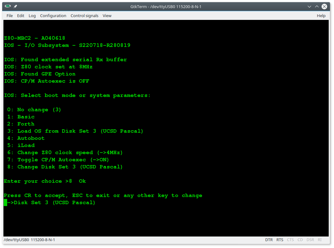
HOW ENTER IN THE "SELECT BOOT MODE OR SYSTEM PARAMETERS" MENU
To enter in the "Select boot mode or system parameters" menu (or simply "boot menu") you must press the RESET key (SW2), release it and press immediately the USER key (SW1) and keep it pressed until the IOS led starts to blink.
An other way is to press both keys, release the RESET key holding the USER key down until the IOS led starts to blink, or you see the menu on the screen.
In the following screenshots is shown the menu when both the RTC module and the GPE option are installed for IOS-LITE and IOS:
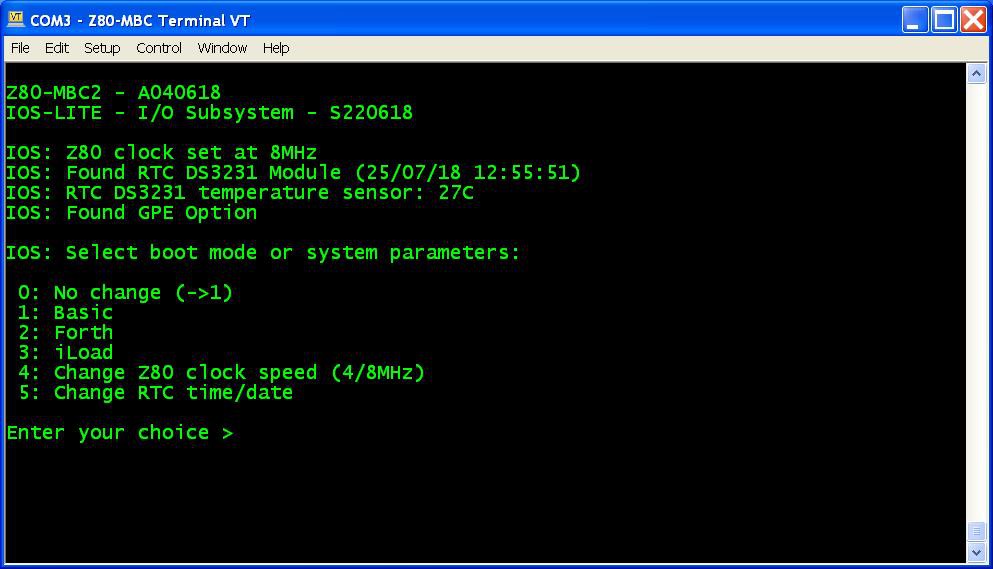
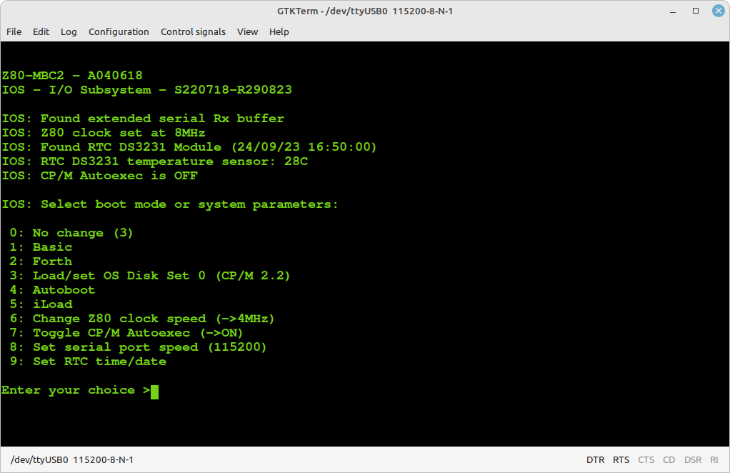
iLoad: loads and executes a Z80 Intel-Hex formatted executable sent from the serial port;
Autoboot: loads and executes a Z80 binary file (AUTOBOOT.BIN) on SD;
Load/set OS Disk Set <n>: loads or changes and runs an Operative System installed into the Disk Set <n> on SD;
Toggle CP/M Autoexec: Turns on or off the execution of the AUTOEXEC batch file at the cold boot. This is supported for CP/M 2.2, CP/M 2.71 and CP/M 3.
The remaining choices are self-explanatory.
In the following it will be assumed the use of the standard IOS, as the IOS-LITE is intended only for a limited use.
THE BAUD RECOVERY VIRTUAL BUTTON
Changing the speed of the serial port may happen "to loose" the control of the board (i.e. you forget the speed or set a wrong speed). In this case you can use a "virtual button" to reset the serial port to the default speed (115200 bps) without the need of a terminal.
To activate the Baud recovery "virtual button" you have to press both the RESET and USER key, release the RESET key holding the USER key down until the USER led starts to blink (like for the "Select boot mode or system parameters" menu) and keeping it down at least for 4 seconds more until both the USER and IOS led start to blink very quickly. This is the sign that the Baud Recovery "virtual button" has been activated.
At the next reboot the serial port will be set at the default speed (115200 bps):
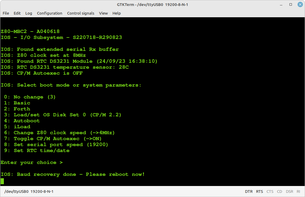
Note: The Baud Recovery virtual button can be triggered only if the serial port is set to a non-default (115200) value.
THE SD IMAGE
The content of the microSD (I'll call it simply SD from now) is compressed into a zip file in the Files section.
When you update the IOS firmware you must always update the content of the SD too, as the SD image is normally suited for a given IOS revision.
You have to unzip it retaining the structure of the sub-directories into a FAT formatted SD card, so that the various root files (inside the .zip as the various .DSK files and so on...) are in the root of the SD itself.
IOS supports only FAT16 and FAT32. A 1GB SD is more than enough, anyway because they tends to be difficult to find now a 4GB SD can be a good choice.
About the SD technology, only "legacy" SD (aka SDSC with a capacity up to 2GB) and SDHC cards (2GB - 32GB) can be used. Other most recent types are not supported (so, no SDXC, SDUC,...).
What it really needed to let IOS run are only all the files in the root folder. The other sub-directories contain source files or examples or other kind of content.
Inside every sub-directory there is a README.TXT file that may contain important info/updates. Please read them all when you use a SD image first time or when update it!
In the root there is a ChangeLog.txt file with the changes log (related to the SD image content).
HOW ADD CP/M FILES INSIDE A VIRTUAL DISK USING CPMTOOLSGUI
The Z80-MBC2 maps any disk like A: B: C: etc. into an image file on SD card with this file name: DSxNyy.DSK;
where x (from 0 to 9) is OS:
0 = CP/M 2.2
1 = QP/M 2.71
2 = CP/M 3
........
and yy (from 00 to 15) is the disk (00 = A: 01 = B: etc.).
You can download CpmtoolsGUI (English Windows version) from here.
Extract the file CpmtoolsGUI.exe in a new folder and add/overwrite the file diskdefs copying it from the folder cpmtools inside the SD.
-> STEP 1
Select in the upper left window (Image File) of the CpmtoolsGUI tool the virtual disk where you want to add files.
For CP/M 2.2 and QP/M 2.71:
select "z80mbc2-d0" only for disk 0 or "z80mbc2-d1" for the others (disk 1 - 15) in the bottom left window (Format) of CpmtoolsGUI.
In the following image is selected (Image File) the disk DS0N02.DSK that corresponds to the disk C: (yy = disk = 02) of the CP/M 2.2 OS (x = 0):
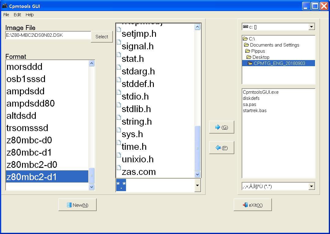
In the center window you can see all the files inside the selected virtual disk (disk 0 - 15).
Please note that if you choose an empty disk (like P:) you won't see any file name in the center window of the CpmtoolsGUI tool.
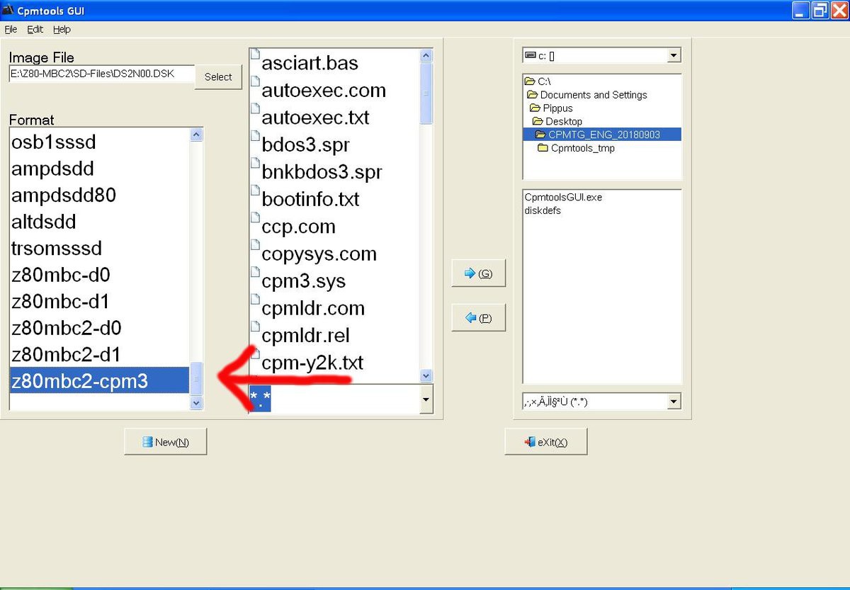
For CP/M 3:
select in the bottom left window (Format) of CpmtoolsGUI "z80mbc2-cpm3" for any disk.
In the following image is selected (Image File) the disk DS2N00.DSK that corresponds to the disk A: (yy = disk = 00) of the CP/M 3 OS (x = 2):
-> STEP 2
To add one or more files to the selected virtual disk you have simply point the upper right selection window to the folder where the new files are stored in your PC, select them using the bottom right selection window and press the "<- P" button. After the add you'll see the added file names in the center window (together with the others file previously present).
-> STEP 3
Exit from the the CpmtoolsGUI tool pressing the eXit button.
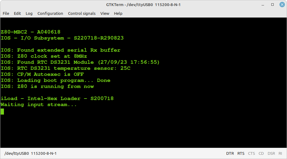
HOW TO USE ILOAD
iLoad is an Intel-Hex format loader that allows to load from the serial port a binary program using the Intel-Hex format, and execute it. You can run it selecting the option 5 from the boot menu (with IOS-LITE the option is 3):
When using iLoad remember to set a 50/90ms delay on every transmitted line into the serial port setting of the SW terminal you are using.
In the following image there is the setting window for TeraTerm inside a Windows XP VM:
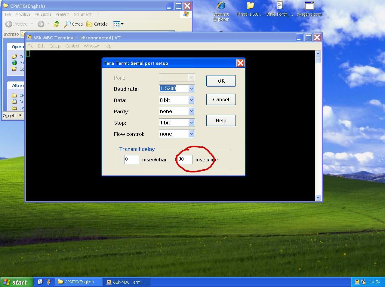
This is required because the standard serial port of the Arduino firmware doesn't use any handshaking control.
Using the iLoad boot mode it's possible to automate all the process from the source to the execution in the target.
Please remember that iLoad will take the first address of the Intel-Hex stream as the starting address of the program, and after the loading will jump to it.
iLoad will also check the hex stream for errors, and protects itself if "someone" try to load a program (or a part) over itself ("illegal address" error).
HOW ENABLE THE EXTENDED RX BUFFER FOR XMODEM (CP/M)
Because the Z80-MBC2 uses a virtual serial port without handshaking there is a timing problem when dealing with the 128 bytes packets used by the XMODEM protocol.
So the support to the XMODEM protocol has requested changes to extend the serial port RX buffer to 128 bytes.
Thanks to user Hans who pointed me to the right direction, there is a simple way to modify the size of the RX buffer used for the serial port.
Search the file boards.txt related with the MightyCore variant in your Arduino IDE.
In a typical Linux Arduino IDE installation it is located in the hidden directory:
/home/<username>/.arduino15/packages/MightyCore/hardware/avr/2.0.5/
or in a Windows 10 installation:
C:\Users\<username>\AppData\Local\Arduino15\packages\MightyCore\hardware\avr\2.0.5
Open board.txt with an editor and locate the section related to the Atmega32/A:
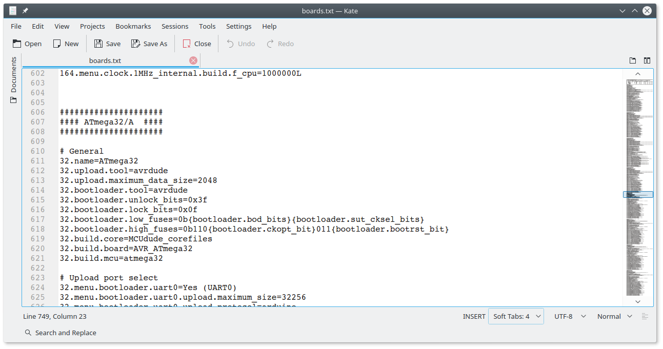
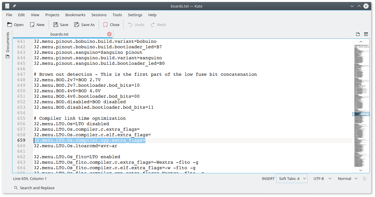
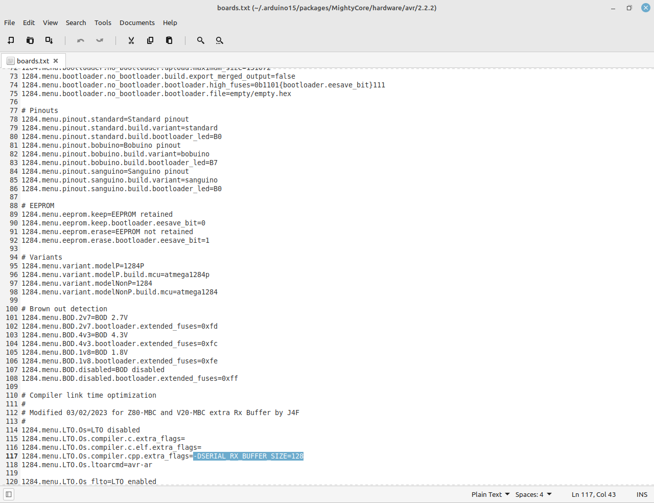
go some lines down until you see the "32.menu.LTO.Os.compiler.cpp.extra_flags=" line:
 then append the string "-DSERIAL_RX_BUFFER_SIZE=128" to that line:
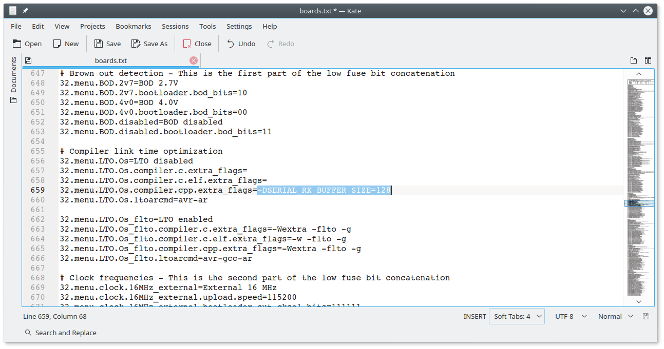
Save the edited board.txt file.
All done!
At this point you can recompile with the LTO option disabled and flash the IOS inside the Atmega32A with the extended RX buffer enabled.
Please remember that if you update the MightyCore you will lose the changes. In this case re-apply the previous steps.
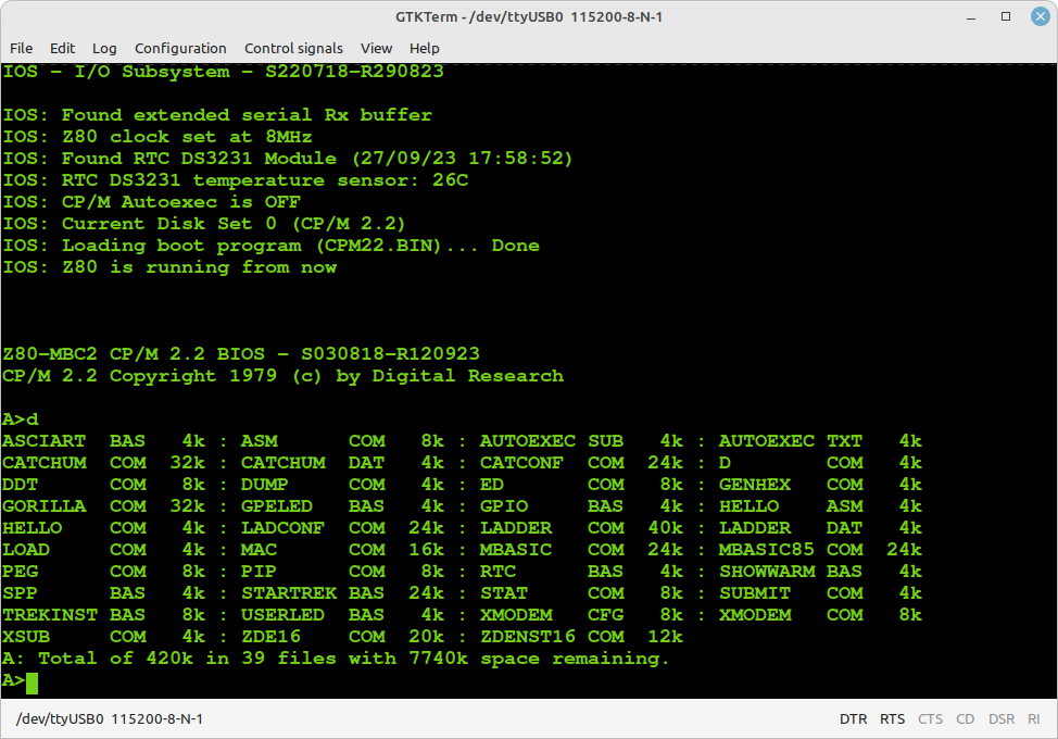
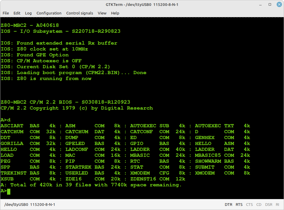
Note that IOS checks if this extended buffer is active, and in this case will print a status line during the boot phase ("IOS: Found extended serial Rx buffer").
CP/M 2.2
To run CP/M 2.2 select it from the boot menu setting the Disk Set 0:
To add, extract or delete files inside a virtual disk (virtual disks filenames on SD are "DS0Nxx.DSK", where "xx" is the disk number) see the paragraph: HOW ADD CP/M FILES INSIDE A VIRTUAL DISK USING CPMTOOLSGUI.
NOTE: The creation of a new CP/M 2.2 boot disk (the first disk DS0N00.DSK) requires further processing (track 0 handling), so is recommended only to add, extract or delete files inside the boot virtual disk (A:).
CP/M 2.2 WARM BOOT MESSAGE
Starting with IOS S220718-R290823 the message shown when CP/M 2.2 makes a warm boot is no more present.
If you are curious about how CP/M 2.2 handles this event it is possible to re-activate it easily.
I've added in the drive A: the utility SHOWWARM.BAS to enable the "warm boot" message.
To execute give the command: MBASIC SHOWWARM:
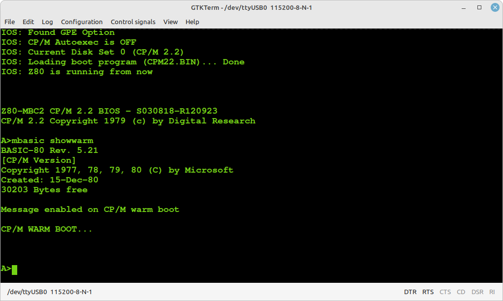
The message will be active until the next reboot.
CP/M 2.2 AUTOEXEC
To enable the AUTOEXEC execution after the cold boot change the corresponding state to ON from the usual IOS boot selection menu.
To edit AUTOEXEC.SUB from drive A, you can use the ED editor. You can test the execution giving the command SUBMIT AUTOEXEC from drive A (you can omit the extension .SUB inside the SUBMIT command).
QP/M 2.71
To run QP/M 2.71 select it from the boot menu setting the Disk Set 1:
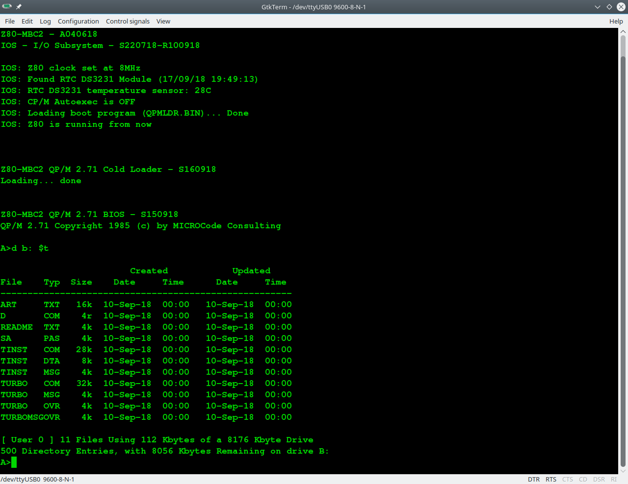
QP/M is an interesting alternative to CP/M developed by MICROCode Consulting that supports also file timestamping, and it is 100% CP/M 2.2 "compatible". MICROCode Consulting has released the original installation files and all the documentation in their site with the "restricted usage" condition, that means free for non-commercial use and for personal use only.
To enable timestamping (see upper screenshot) you need to install the optional RTC module.
I suggest to read the QP/M documentation for the various commands (see the Downloads section in their site).
QP/M 2.71 AUTOEXEC
The QP/M uses for the batch file the .QSB extension. So the AUTOEXEC file is here named AUTOEXEC.QSB. To enable the AUTOEXEC execution after the cold boot change the corresponding state to ON from the usual IOS boot selection menu. In the drive A: there is an example of AUTOEXEC.QSB file ready to run.
CP/M 3
To run CP/M 3 select it from the boot menu setting the Disk Set 2:
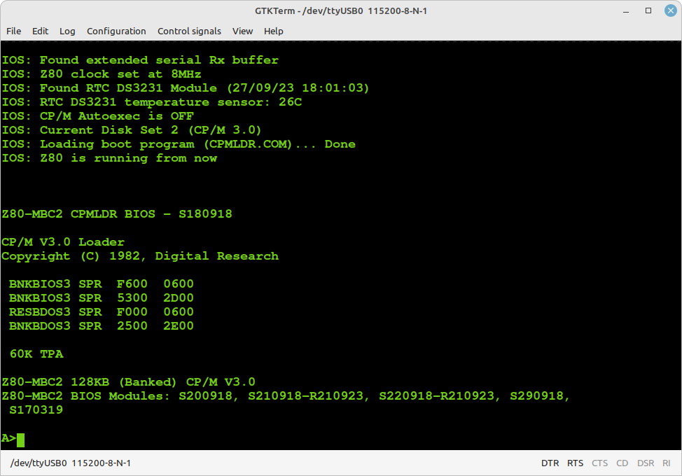
With CP/M 3.0 it is possible use the 128KB banked RAM to have a wider user area (TPA) for programs and a more "evoluted" OS.
Just as example of how it is easy with CP/M 3.0 manage multiple configurations, I've done also a "non-banked" 64KB version. The switch from one version to the other can be done simply running a batch from the console itself.
I've prepared two simple batch files to do that. From drive A: the command:
submit sys64
will set the 64KB "non-banked" version and then reboot the system.
To activate again the 128KB "banked" version give the command (from drive A:):
submit sys128
CP/M 3 AUTOEXEC
The AUTOEXEC switch for CP/M 3.0 works in a different way from the CP/M 2.2 and QP/M 2.71 implementations.
Now there is a custom utility (AUTOEXEC) that checks the IOS flag and sets the exit code accordingly (using the BDOS function 108). This allow to use the CP/M 3.0 batch conditional execution (see the CP/M 3 Programmer Guide par. 1.6.3) to run any wanted command or program based on the status of the IOS AUTOEXEC flag.
I've prepared an example using an other CP/M 3.0 feature, the "PROFILE.SUB" batch that is automatically executed at cold boot (if it exists). To activate it (in the drive A:) rename the file PROFILE.SU as PROFILE.SUB with the command:
ren profile.sub=profile.su
Now you can see how it works setting the AUTOEXEC flag on or off with the IOS "Select boot mode or system parameters" menu.
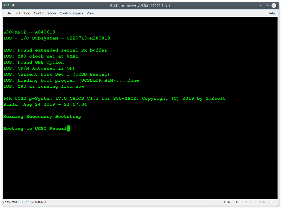
UCSD PASCAL
Thanks to Michel Bernard (a member of the Z80-MBC2 User Group on FB) who did the porting, now UCSD Pascal is running on the Z80-MBC2!
To run UCSD Pascal select it from the boot menu setting the Disk Set 3:
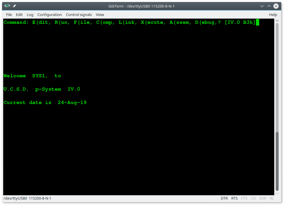
In the SD image there are two volumes (disks) SYS1: and SYS2:
 Here the execution of an example (SINE.CODE) already compiled on the SYS2: disk:
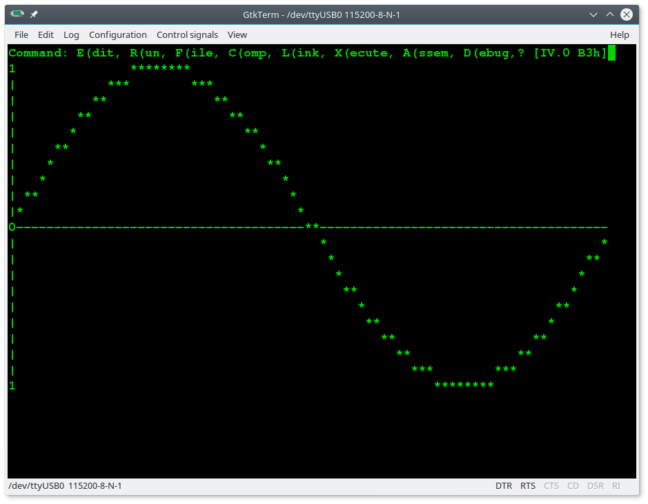
In the folder "UCSD Pascal" inside the SD there are the original files and sources provided by Michel Bernard (https://github.com/GmEsoft/Z80-MBC2_UCSDP).
A lot of documentation and books about UCSD Pascal can be found here.
COLLAPSE OS
To run Collapse OS select it from the boot menu setting the Disk Set 4:
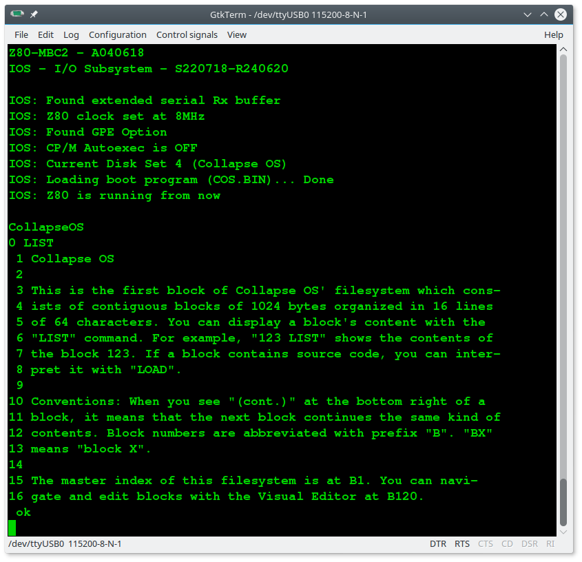
For more info the Collapse OS site is here.
FUZIX OS
To run Fuzix OS select it from the boot menu setting the Disk Set 5:
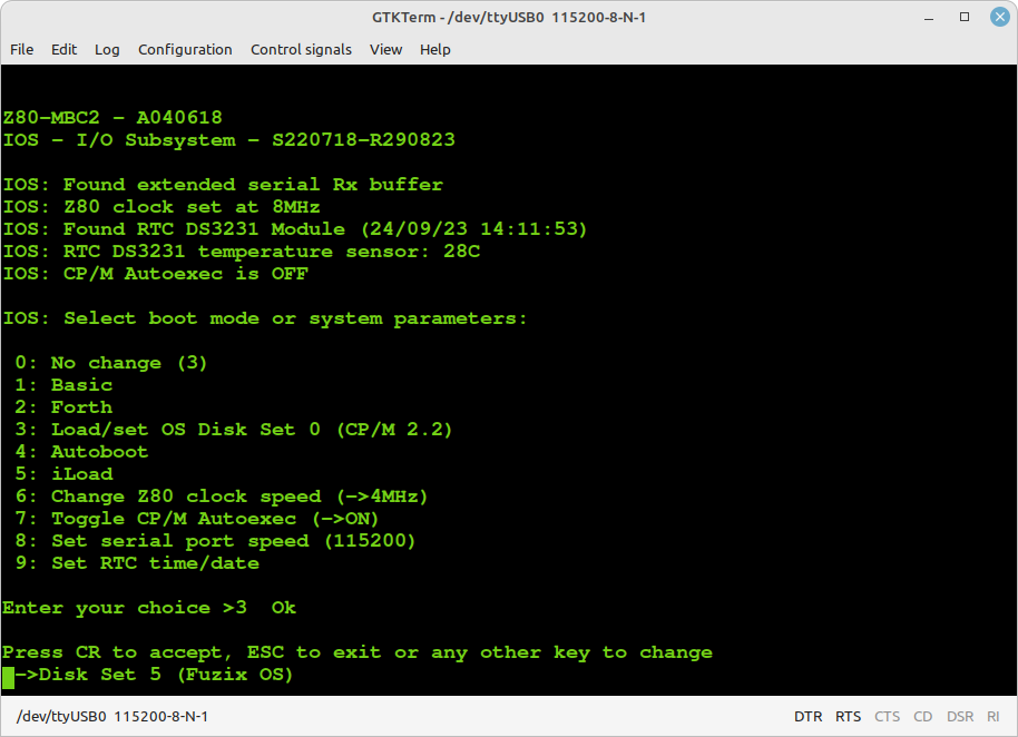
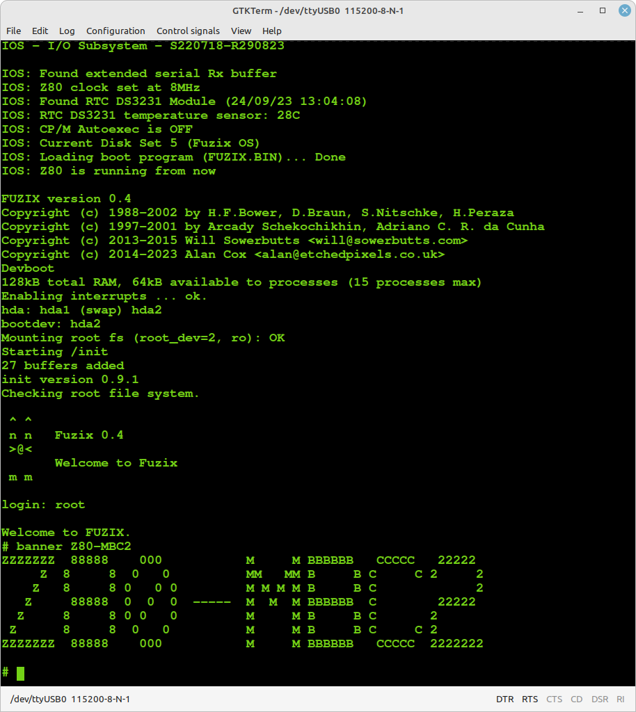
You have to select hda2 as bootdev device when asked, and then log as root user (no password):
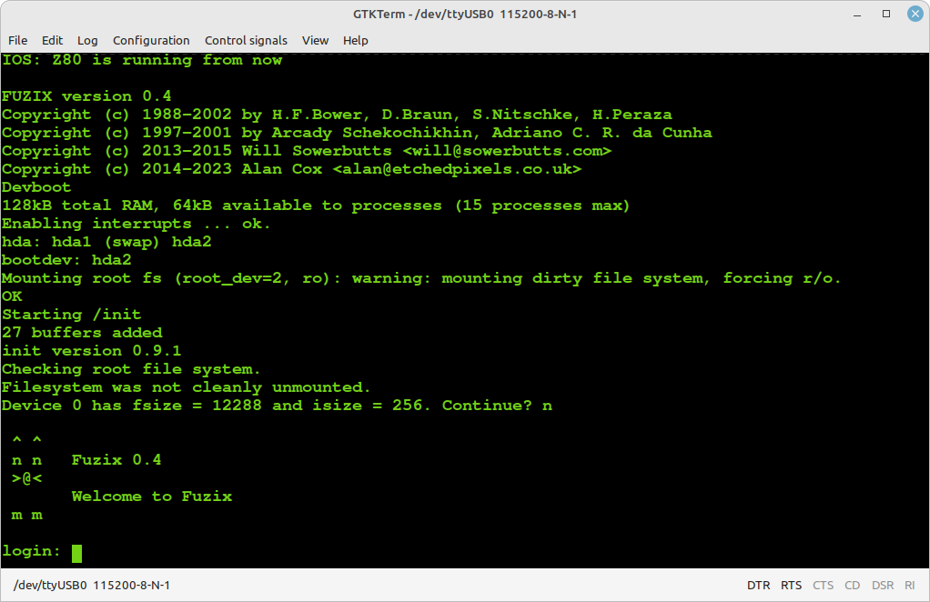
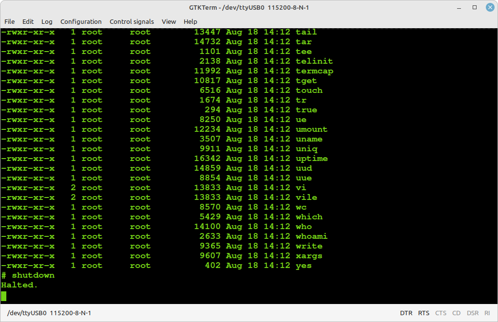
Remember to give the shutdown command before powering off to avoid the file system warning and checking at the next Fuzix reboot:
For more info the Fuzix OS site is here.
HOW BUILD FUZIX OS FROM SCRATCH
Building Fuzix OS ( https://github.com/EtchedPixels/FUZIX ) for a Z80 CPU with banked RAM requires a special patched version of SDCC available from here: https://github.com/EtchedPixels/sdcc280 .
This special SDCC version is source only, and it needs to be compiled.
These instructions have been written using an Ubuntu based Linux distro (Linux Mint 20.3). Aside from the package installation commands, the rest of the steps should work with many other Linux distributions as well.
STEP 1:
First, install the necessary packages, if they are not already there (they should...):
sudo apt-get install gcc
sudo apt-get install build-essential
sudo apt-get install automake gputils flex texinfo bison byacc
STEP 2:
Install the following package that is not usually present on a Ubuntu based distro:
sudo apt-get install libboost-all-dev
STEP 3:
Now get the special version of the SDCC compiler for Fuzix:
git clone https://github.com/EtchedPixels/sdcc280.git
and give the following commands to compile and install it:
cd sdcc280
cd sdcc
./configure
make
sudo make install
cd ../..
STEP 4:
Get Fuzix source code:
git clone https://github.com/EtchedPixels/FUZIX.git
cd FUZIX
STEP 5:
Modify the Makefile and change the line that says TARGET=..... to be TARGET=z80-mbc2 and compile it (it can take hours...):
sudo make
STEP 6:
Now create the fuzix.bin file and the virtual disk file (.DSK) with the command (from the same directory):
sudo make diskimage
All done! In the folder FUZIX/Images/z80-mbc2 you'll get:
fuzix.bin
DS0N01.DSK
Rename DS0N01.DSK as DS5N01.DSK and copy both files into the SD of the Z80-MBC2 SBC.
NOTE: This guide was adapted from here: http://www.forofpga.es/viewtopic.php?t=422
* * USING THE SDCC CROSS COMPILER * *
Click on the link above to read this chapter.
* * USING THE TASM CROSS ASSEMBLER * *
Click on the link above to read this chapter.
* * OVERCLOCKING THE Z80-MBC2 * *
Since the Mighty Core gives the chance to choice a 20MHz bootloader, I've decided to try to "overclock" the Atmega32A using a 20MHz quartz:
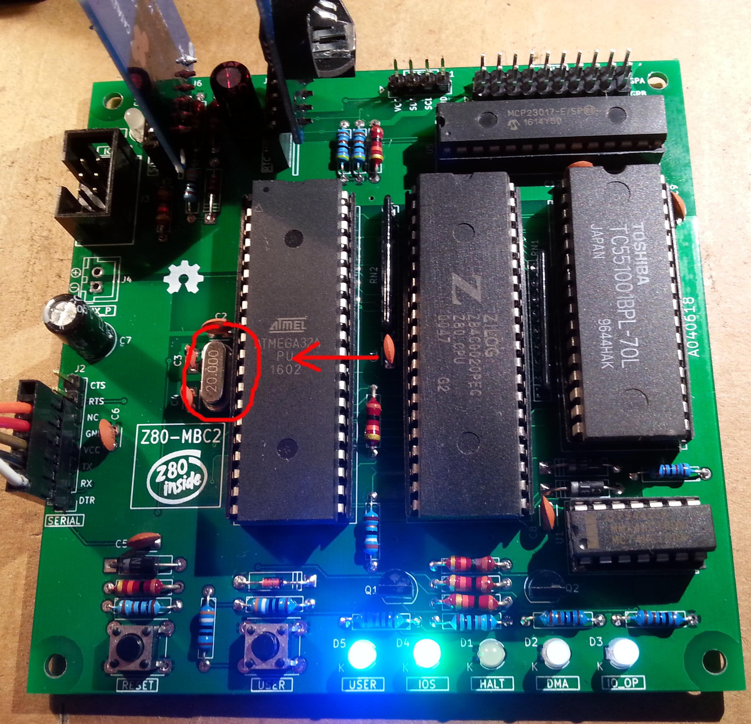
You don't need others HW changes, just use a 20MHz quartz instead of a 16MHz one. The Z80 clock speed will be at 10MHz.
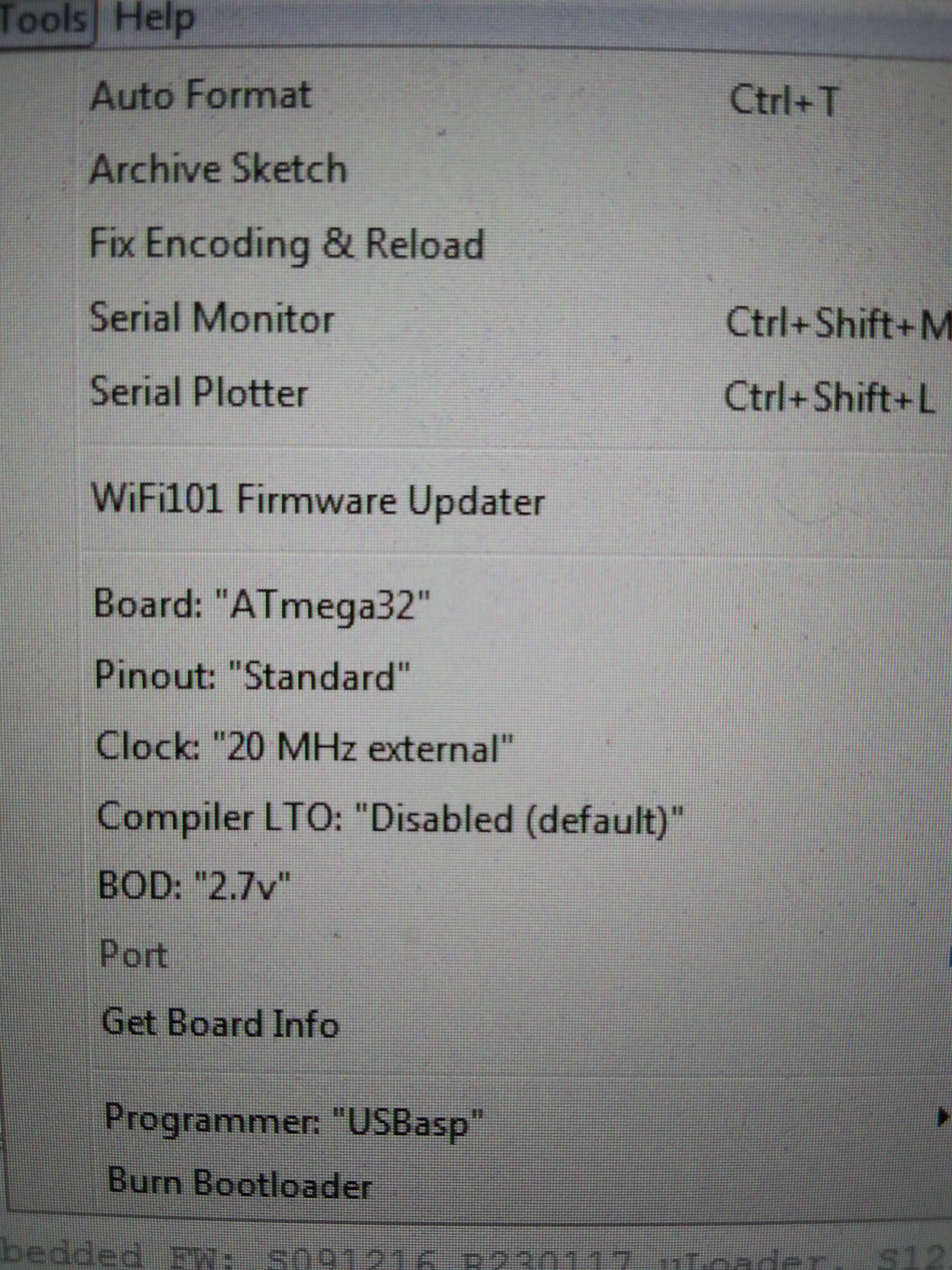
You have to select the "20MHz external" option in the "Toos" menu of Arduino IDE before flashing the 20MHz bootloader:
 Of course you need to load the sketch again (using the "20MHz external" option). IOS will display the new clock speed:
Remember that using a 20MHz quartz you are out of the Atmega32a specifications (the Atmega32a is rated at 16MHz max.), so you are in a "grey area" where things "may works"...
* * USING AN ATMEGA1284/ATMEGA1284P * *
Starting with IOS S220718-R290823 it is possible to use an Atmega1284/Atmega1284P as MCU. This will leave more space for any customization.
Of course you have to re-compile the IOS source selecting the right MCU.
Remember to apply the changes described in the paragraph "HOW ENABLE THE EXTENDED RX BUFFER FOR XMODEM (CP/M)" searching for the Atmega1284 section:
* * PROJECT STATUS * *
Currently both IOS-LITE and IOS are available. The first is a simplified version that doesn't support the SD, the second is a full featured version that requires the SD module (e. g. to run CP/M).
The current revision of IOS allows you to run CP/M 2.2, CP/M 3.0, QP/M 2.71, UCSD Pascal, Collapse OS and Fuzix OS (and the stand-alone versions of Basic and Forth, the same supported by IOS-LITE) with 16 virtual disks (8Mbytes each) for each OS.
Support files for the SDCC cross-compiler have been added inside the SD image (/SDCC folder), including interrupt handling.
The add-on board uTerm has been released.
The add-on board uCom has been released.
The SPP Adapter board (parallel printer standard interface) is supported under CP/M 2.2 and CP/M 3 (banked).
Not suited for aerospace applications! ☻
* * HOW TO GET A PCB * *
Because some people asked about this, I've prepared an "easy" link to get a small lot (5 pcs minimum) of PCB. The link is this one.
* * HOW TO GET A KIT OR AN ASSEMBLED UNIT * *
If you are looking for a kit with all the needed parts or an assembled unit ready to use now there is a professional seller that can sell both and ship worldwide.
The link to the seller is this one.
* * Z80-MBC2 USER GROUP * *
An "User Group" was created on Facebook: https://www.facebook.com/groups/Z80MBC2.
* * LICENSING AND CREDITS * *
All the project files (SW & HW) are licensed under GPL v3.
If you use this material in any way a reference to the author (me ☻) will be appreciated.
CP/M seems to be Open Source now (see here).
PetitFS was developed by ChaN.
Basic stand-alone interpreter was an adaptation from Grant Searle work.
Forth stand-alone interpreter was originally ported to the Z80-MBC by Bill Westfield.
UCSD Pascal was ported by Michel Bernard.
Collapse OS was designed and ported by Virgil Dupras.
Fuzix OS was designed and ported by Alan Cox (www.fuzix.org).