Close
0%
0%

Z80-MBC2: a 4 ICs homebrew Z80 computer

Homemade 8MHz Z80 SBC, 128kB banked RAM, RTC, SD (HD emulation), Basic and Forth interpreter, CP/M 2.2 and 3, UCSD Pascal, Fuzix and more...

Similar projects worth following
The Z80-MBC2 is an easy to build Z80 SBC (Single Board Computer).It is the "evolution" of the Z80-MBC (https://hackaday.io/project/19000), with a SD as "disk emulator" and with a 128KB banked RAM for CP/M 3 (but it can run CP/M 2.2, QP/M 2.71, UCSD Pascal, Collapse OS and Fuzix too).

It has an optional on board 16x GPIO expander, and uses common cheap add-on modules for the SD and the RTC options. It has an "Arduino heart" using an Atmega32A as EEPROM and "universal" I/O emulator (so a "legacy" EPROM programmer is not needed).

It is a complete development "ecosystem", and using the iLoad boot mode it is possible cross-compile, load and execute on the target an Assembler or C program (using the SDCC compiler) with a single command (like in the Arduino IDE).


* * HARDWARE OVERVIEW * *

The needed ICs for the "base system" are:

  • Z80 CPU CMOS (Z84C00) 8Mhz or greater
  • Atmega32A
  • TC551001-70 (128kB RAM)
  • 74HC00

If you want the 16x GPIO expansion (GPE option) add a MCP23017 too.

The schematic and the BOM are attached in the Files section. The MCU Atmega32A is used as universal I/O subsystem, as Eeprom, and as reset and 4/8MHz clock generator for the Z80 CPU.
Inside the Atmega32A it is flashed an Arduino bootloader taken from here, and it is possible to use the Board Manager of the Arduino IDE to "import" it.

Flash the Arduino bootloader at first (with the method you prefer), next you can upload the IOS "sketch" (the I/O Subsystem that interacts with the Z80 bus and "virtualizes" the EEPROM and all the peripherals seen by the Z80 CPU) using Arduino IDE.

You can use the on board ICSP port J3 (also called ISP port) to write the bootloader, but remember to disconnect any other connector when using it. Also both SD and RTC modules (if present) must be removed from the board when the ICSP port is in use.

As clock source for the Z80 CPU it is used the 16MHz Atmega32A oscillator, so the "external 16MHZ osc." bootloader variant must be chosen when flashing the bootloader from the Arduino IDE!.

The 74HC00 is used as RS flipflop to stop the Z80 CPU during I/O operation, giving the needed time to the Atmega32A to interact with the Z80 bus, and as part of the MMU.

Note that only the CMOS version of the Z80 CPU can be used here. This because only CMOS version, under given condition that are respected in this schematic, has logical levels compatibles with Atmega32A and 74HC00.


NOTES ABOUT THE COMPONENTS

You should use a  Z80 CMOS speed grade of at least 8MHz for full speed, but setting the clock speed at 4MHz you can use a 4MHz Z80 CMOS version too (or you can try to overclock it at 8MHz...). The 74HC00 can be substituted with a 74HCT00 if you already have one. The RAM chip TC551001-70 can be substituted with any suitable 128kB SRAM).

Please note that the USER led  * must * be blue or white (or pink... I've some pink leds that seems to have a Vf like blue one. May be I'll do a board with them...) just to be sure that V(forward) is >= 2.7V (otherwise the USER key may not work as expected).

The J4 connector (AUX_P) is not currently supported and is not populated by default.

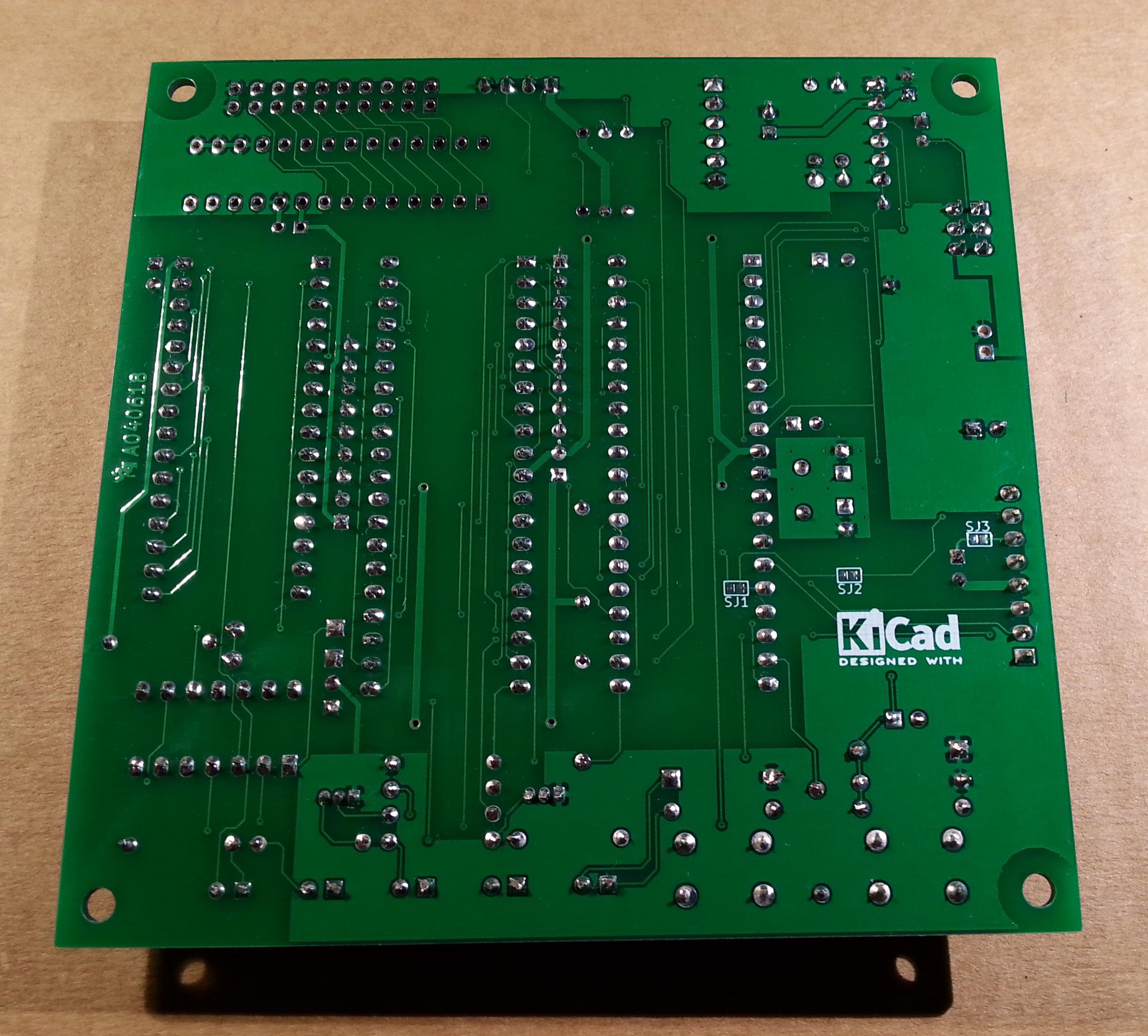
The three solder jumpers (SJ1-3) on the bottom side are not currently supported and must  be left opened (as stated in the schematic).


THE SERIAL PORT

The  SERIAL port (J2, see schematic) can be connected with a TTL-RS232 adapter, or with a serial-USB adapter.
I've used a serial-USB adapter that acts also as power source for the Z80-MBC, and has the DTR signal for the "autoreset" driven from the Arduino IDE. For a terminal that has a serial TTL port no adapter is needed.

Of course to upload a "sketch" from Arduino IDE you need to use a serial-USB adapter connected to the SERIAL port.

Note that the RTS and CTS pins of the SERIAL port are not currently supported and must be left not connected (as the NC pin!).

The 3V3 pin of the serial-USB adapter must be left disconnected  (if present).

You should use those Serial-USB adapters that have the DTR pin on the connector. It is suggested to have also the CTS/RTS signals available for future upgrades.

Please note that all the pin names of J2 on the PCB are referred to the serial-USB adapter, so all the signals as TX and RX are relative to the serial-USB adapter side (in other words TX and RX are already "inverted". See the schematic).

Here a suggested serial-USB adapter based on a CP2102 (very common on ebay):


THE OPTIONAL RTC MODULE

The RTC is a common module based on a DS3231  RTC  like this one:

This cheap modules have a trickle charging circuit that may cause the "explosion" of the battery if you use a standard CR2032 cell. More, it can damage also a rechargeable LIR2032...

Read more »

S220718-R290823_IOS-Z80-MBC2.zip

The sketch for the IOS (with the needed libraries). Unzip into a folder and open the .ino file (with Arduino IDE). IOS must be uploaded into the Atmega32A flash. Adds support for Fuzix OS and the SPP Adapter board (more info in the changelog inside the .ino file).

Zip Archive - 43.75 kB - 09/24/2023 at 11:59

Download

S220718-R290823_IOS-Z80-MBC2.ino.with_bootloader_atmega32_16000000L.hex

The sketch for the IOS in executable format (.HEX) with the bootloader. This executable file is intended for use with a programmer as the Atmel Ice or AVRISPmkII or others (Fuse bits: High Byte 0xD6, Low Byte 0xAF, Lock Byte 0xCF)

x-hex - 59.90 kB - 09/24/2023 at 12:04

Download

SD-S220718-R290823-v1.zip

The content of the microSD needed to run CP/M 2.2, CP/M 3.0, QP/M 2.71, UCSD Pascal, Collapse OS and Fuzix with IOS S220718-R290823 (More info in the Changelog.txt file inside)

Zip Archive - 5.79 MB - 09/24/2023 at 12:02

Download

SPP Adapter board - A240721-R270921.zip

All the documentation needed to build the SSP (Standard Parallel Port) Adapter board (A240721-R270921) including schematic, PCB assembling guide, Gerber files for PCB production. PCB is 55mm x 60mm 2-layers.

Zip Archive - 747.10 kB - 09/24/2023 at 15:10

Download

STARTREKV2.BAS

The famous game Super Startrek kindly debugged by a RetroBrew Computer Forum user. Play with Caps-Lock activated! Now the animation works...

bas - 20.18 kB - 08/07/2018 at 16:32

Download

View all 12 files

  • 1 × See the file "A040618 BOM v2.ods" in the FILES section.

  • UCSD Pascal for the Z80-MBC2!

    Just4Fun09/01/2019 at 15:45 3 comments

    Thanks to Michel Bernard (a member of the Z80-MBC2 User Group on FB) who did the porting, now UCSD Pascal is running on the Z80-MBC2!

    Michel Bernard originally used the trick to create a custom autoboot.bin file to be used with the "Autoboot" boot selection to load the OS.

    Because this porting is so cool, I've done a new IOS version and a new SD image to support UCSD Pascal in the same way as the others previous OS, adding a new "Disk Set" selection:


    To run UCSD Pascal you just need to update the new IOS and the new SD image (in the Files section) and select it from the usual "Select boot mode or system parameter" menu:


    In the new SD image there are two volumes (disks) SYS1: and SYS2:


    Here the execution of an example (SINE.CODE) already compiled on the SYS2: disk:


    In the folder "UCSD Pascal" inside the SD there are the original files and sources provided by Michel Bernard.
    A lot of documentation and books about UCSD Pascal can be found here.

  • uCom is out!

    Just4Fun05/29/2019 at 09:20 0 comments

    I've done a separate "project page" for uCom (RS232 add-on card for the Z80-MBC2) here.

    The uCom board, as the uTerm VT100 board, has a "transparent" USB-serial adapter connector, so you can upload firmware to the Z80-MBC2 (using Arduino IDE) or load an Intel-Hex file (with iLoad) or use XMODEM to exchange files with a PC (running a terminal emulator that supports XMODEM file transfer) while the uCom is in use.

    Both the "mixed" power supply scenarios (USB-serial adapter not powered from USB but Z80-MBC2 powered and vice-versa) are managed by the HW, so you don't need to worry about it.

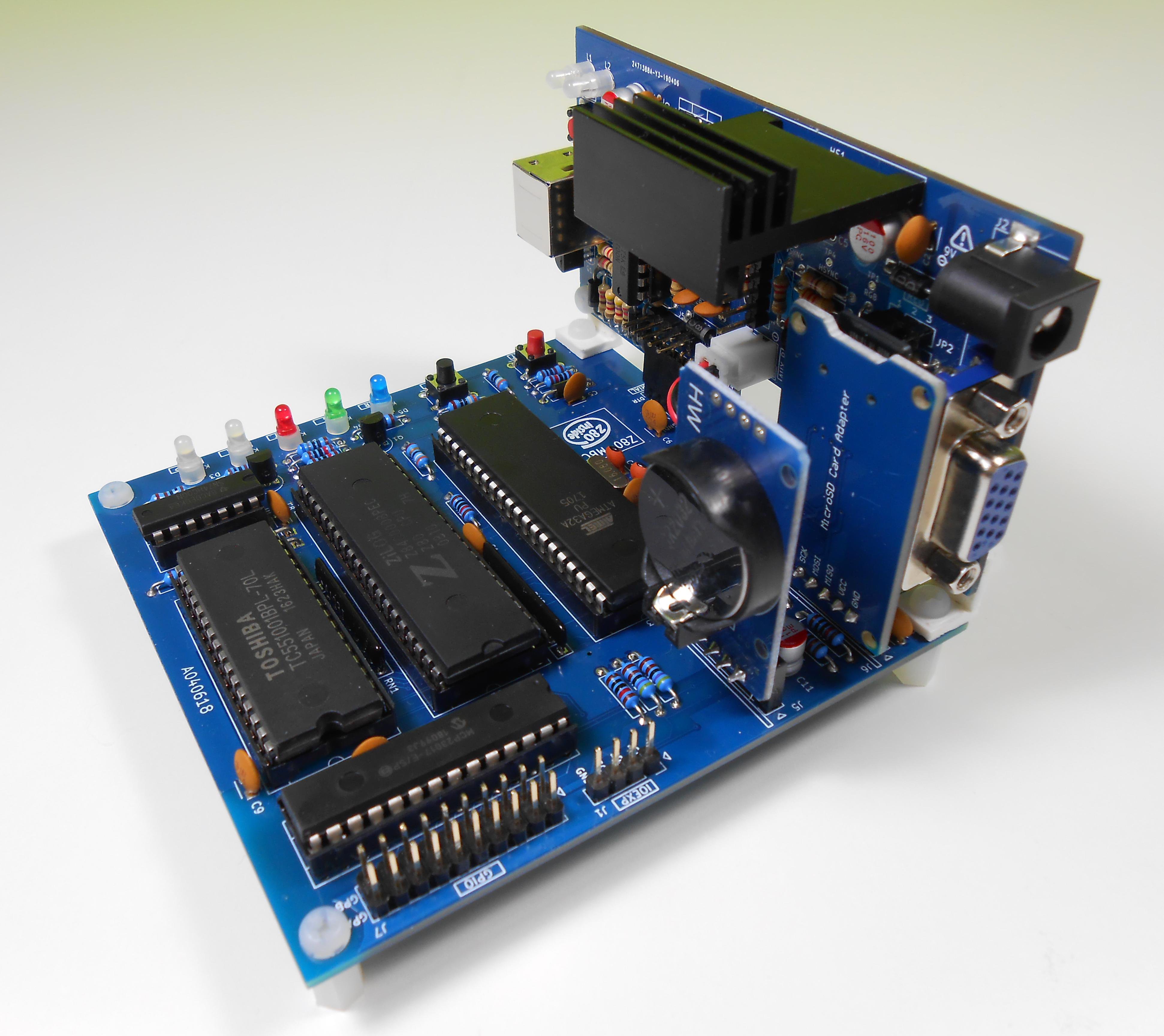
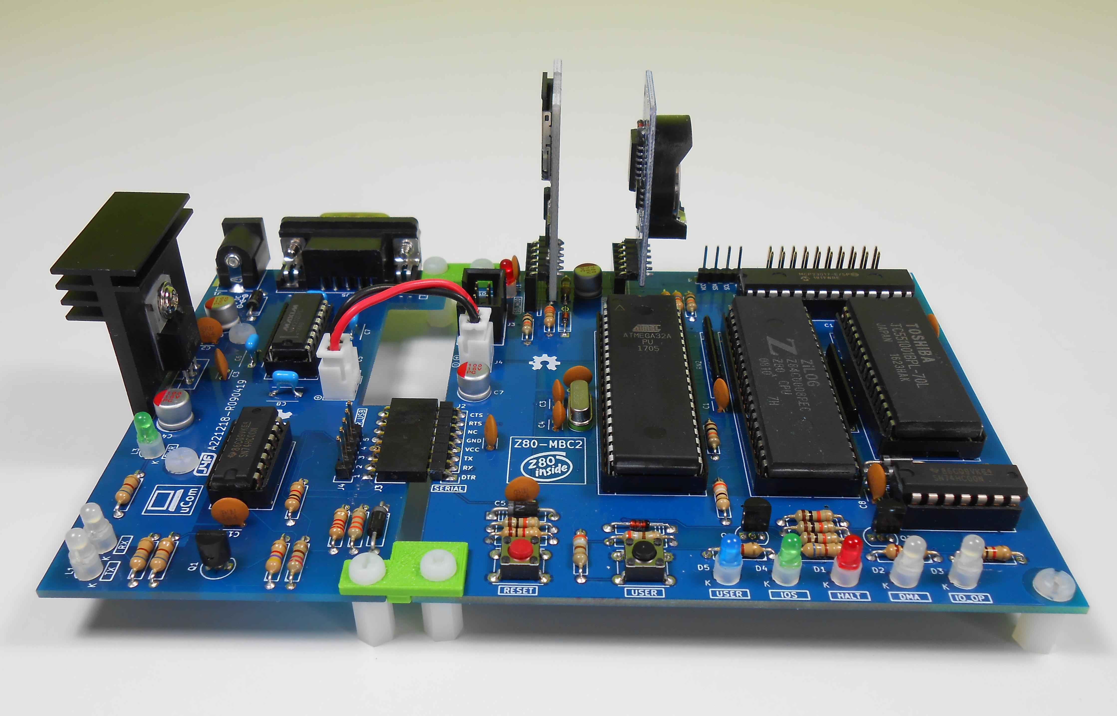
    uCorm can be mounted horizontally or vertically to the Z80-MBC2.

    The 3D printed custom angled brackets .STL files are the same of the uTerm.


    Here connected with a "vintage" RS232 terminal (Ampex 210 relabeled Kyber):

  • uTerm is out!

    Just4Fun05/14/2019 at 07:40 0 comments

    I've done a separate "project page" for uTerm here.

    uTerm can be mounted horizontally or vertically to the Z80-MBC2.

    All the details including the 3D printed custom angled brackets .STL files are there.

    uTerm is a VT100 terminal with VGA out and  PS/2 keyboard with a power supply (for the Z80-MBC2 too). It has a "transparent" USB-TTL adapter connector, so you can upload firmware or load an Intel-Hex file (with iLoad) while the card is inserted. Both the "mixed" power supply scenarios (USB-TTL adapter not powered from USB but Z80-MBC2 powered and vice-versa) are managed. The video terminal is based on the ChibiTerm (https://hw-by-design.blogspot.com/2018/07/low-cost-vga-terminal-module-project.html).


  • New IOS for XMODEM support

    Just4Fun03/10/2019 at 10:54 6 comments

    Because some people requested to use the XMODEM protocol to exchange files through the serial port, I've added the support for this protocol into CP/M 2.2 and CP/M 3 (banked only).

    XMODEM needs a full 8 bit binary data transfer, and this is not possible with the CON port (the CP/M port used for the console) with a "legacy" CP/M system installation because the CP/M Alteration Guide says to strip the eight parity bit when reading a byte from the console input.

    More, because the Z80-MBC2 uses a virtual serial port without handshaking there is also a timing problem when dealing with the 128 bytes packets used by the XMODEM protocol.

    So the support to the XMODEM protocol has requested changes in the IOS and  in the CP/M BIOS, and also in the Arduino core to extend the serial input buffer.

    Please note that with the new IOS the default speed of the serial port is now 115200 bps.

    To have the XMODEM support active, before the update of the new IOS firmware and the new SD image (see in the Files section),  you have to manually create a new "board variant" in the Arduino IDE and then change the default Rx input buffer size to 128 bytes in the "core" of this new variant.

    If you aren't interested into the XMODEM support, you can simply update the IOS and the new SD image as usual  without the need to create the new board variant. In this case the XMODEM will not work in the receive direction, but only in the send direction (from the Z80-MBC2 to a PC with a terminal emulator).


    HOW MANUALLY CREATE A NEW BOARD VARIANT (LINUX)

    In the following I'll assume an Arduino IDE 1.8.5 installation on a linux host and the MightyCore ver. 1.0.8. Anyway I've tried to make the procedure enough general to be used for other versions too.

    The first thing is find the directory where the MightyCore is located.

    If you have installed Arduino IDE 1.8.5 and then installed the MighyCore with the Board Manager with the usual .json "pointer", the MightyCore is located in the "~/.arduino15/packages/MightyCore" directory:

    Now you must locate the "~/.arduino15/packages/MightyCore/hardware/avr/1.0.8/cores" directory (note that the "1.0.8" part of the directory name depends on the MightyCore version, and so can be a different number if you have a different version of the MighyCore):

    ... Read more »

  • Overclocking the Z80-MBC2...

    Just4Fun11/02/2018 at 09:51 4 comments

    Because the Mighty Core gives the chance to choice a 20MHz bootloader, I've decided to try to "overclock" the Atmega32A using a 20MHz quartz:

    You don't need others HW changes, just use a 20MHz quartz instead of a 16MHz one. The Z80 clock speed will be at 10MHz.

    You have to select the "20MHz external" option in the "Toos" menu of Arduino IDE before flashing the 20MHz bootloader:


    Of course you need to load the sketch again (using the "20MHz external" option). IOS will display the new clock speed:


    Remember that using a 20MHz quartz you are out of the Atmega32a specifications (the Atmega32a is rated at 16MHz max.), so you are in a "grey area" where things "may works"...

  • CP/M 3 up and running on the Z80-MBC2!

    Just4Fun10/11/2018 at 06:58 0 comments

    With the latest IOS revision and the corresponding new SD image (see the Files section) there is one more option: the CP/M 3.0!

    With CP/M 3.0 it is possible use the 128KB banked RAM to have a wider user area (TPA) for programs and a more "evoluted" OS.


    TWO VERSIONS

    Just as example of how it is easy with CP/M 3.0 manage multiple configurations, I've done also a "non-banked" 64KB version. The switch from one version to the other can be done simply running a batch from the console itself.

    I've prepared two simple batch files to do that. From drive A: the command:

    submit sys64

    will set the 64KB "non-banked" version and then reboot the system.

    To activate again the 128KB "banked" version give the command (from drive A:):

    submit sys128

    NEW DISKDEFS FILE

    To use cpmtools or cpmtoolsGUI with the virtual disks of the CP/M 3.0 environment, you must update the DISKDEFS definition file (from the SD in the folder <SD>/cpmtools/) and use the "z80mbc2-cpm3" entry for all the 16 disks:

    Please note that for the CP/M 3.0 environment all the 16 virtual disks have the same structure and for this there is only one entry for all the CP/M 3.0 virtual disks.


    AUTOEXEC

    The AUTOEXEC switch for CP/M 3.0 works in a different way from the CP/M 2.2 and QP/M 2.71 implementations.

    Now there is a custom utility (AUTOEXEC) that checks the IOS flag and sets the exit code accordingly (using the BDOS function 108). This allow to use the CP/M 3.0 batch conditional execution (see the CP/M 3 Programmer Guide par. 1.6.3) to run any wanted command or program based on the status of the IOS AUTOEXEC flag.

    I've prepared an example using an other CP/M 3.0 feature, the "PROFILE.SUB" batch that is automatically executed at cold boot (if it exists). To activate it (in the drive A:) rename the file PROFILE.SU as PROFILE.SUB with the command:

    ren profile.sub=profile.su

    Now you can see how it works setting the AUTOEXEC flag on or off with the IOS "Select boot mode or system parameters" menu.

  • QP/M 2.71 up and running (with IOS multi-boot management...)!

    Just4Fun09/17/2018 at 18:26 0 comments

    With the latest IOS revision and the corresponding new SD image (see the Files section) there is an interesting alternative to CP/M developed by MICROCode Consulting that supports also file timestamping, and it is 100% CP/M 2.2 "compatible".
    MICROCode Consulting has released the original installation files and all the documentation in their site with the "restricted usage" condition, that means free for non-commercial use and for personal use only.

    To enable timestamping (see upper screenshot) you need to install the optional RTC module.
    I suggest to read the QP/M documentation for the various commands (see the Downloads section in their site).


    AUTOEXEC

    The QP/M uses for the batch file the .QSB extension. So the AUTOEXEC file is now renamed AUTOEXEC.QSB. To enable the AUTOEXEC execution after the cold boot change the corresponding state to ON from the usual IOS boot selection menu. In the drive A: there is an example of AUTOEXEC.QSB file ready to run.


    IOS MULTI-BOOT MANAGEMENT

    Now the IOS has a new entry (8) in the boot menu to manage the OS multi-boot configuration:

    Each OS is associated with a set of virtual disks called "Disk Set", and changing the "Change Disk Set..." entry (8) will switch all the virtual disks of his "environment".

  • CP/M 2.2 up and running on the Z80-MBC2!

    Just4Fun09/08/2018 at 18:24 0 comments

    The new IOS is out, and the CP/M 2.2 OS with it, and 16 disks are available (from A: to P:), each 8Mbyte large.

    With IOS (not for IOS Lite) the SD module is mandatory to run not only CP/M 2.2 but also for the stand-alone Basic and Forth interpreters. You need a microSD card (FAT16 and FAT32 are both supported) to store the content of the SD image file, retaining the directory structure.

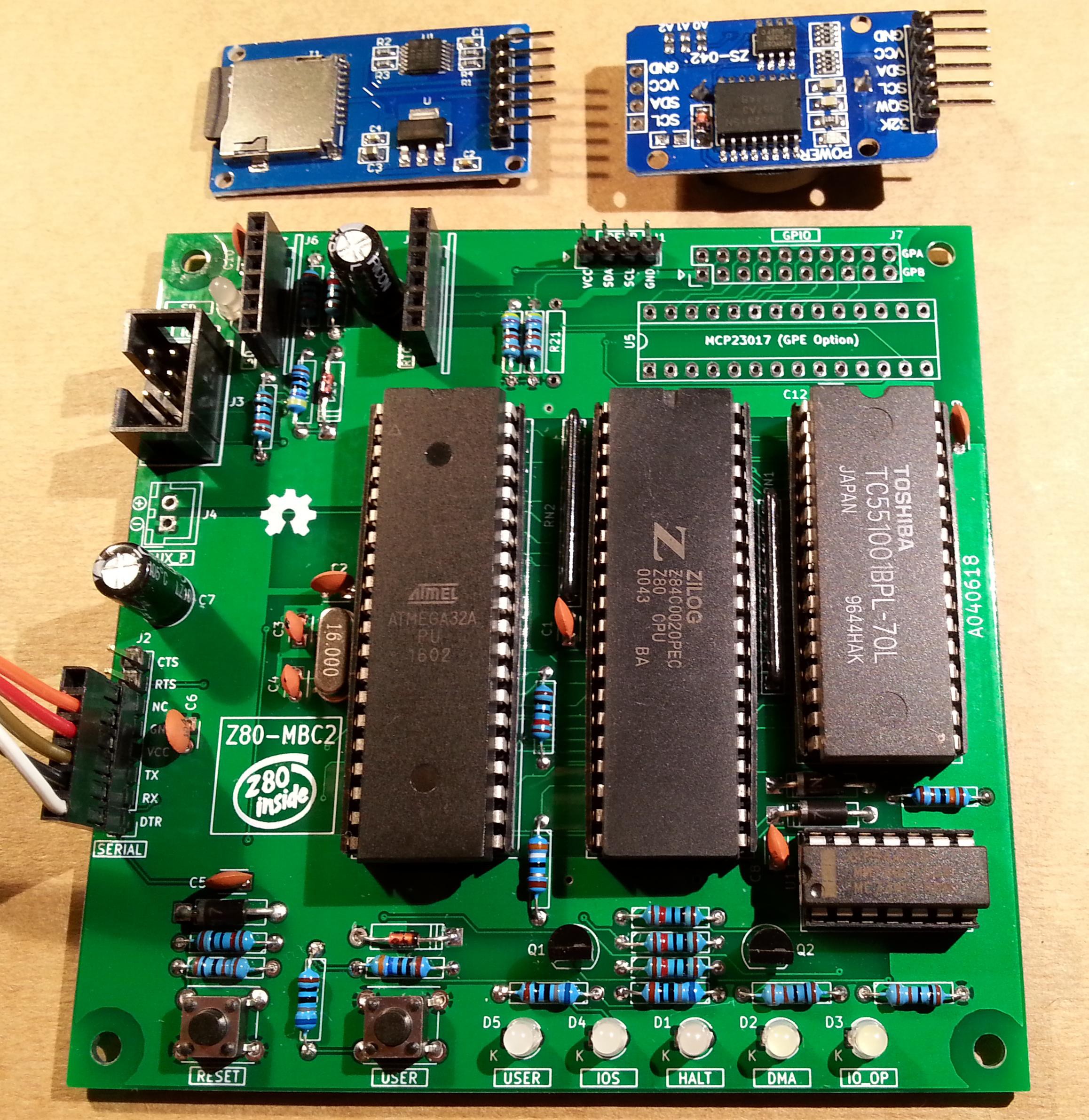
    Pay attention on how the modules are inserted because their positions are fixed and absolutely not swappable (see the upper photo).

    To add, extract or delete files inside a virtual disk (virtual disks filenames on SD are "DS0Nxx.DSK", where "xx" is the disk number) it is possible use the cpmtools or cpmtoolsGUI utilities, with the diskdefs file in the \cpmtools directory of the SD zipped file.

    I suggest to use  cpmtoolsGUI (only for Windows) because is very easy.

    Unzip it into a folder and put the diskdefs file in the same folder.
    Select "z80mbc2-d0" only for disk 0, and "z80mbc2-d1" for the others (disk 1 - 15):

    NOTE: use cpmtoolsGUI only to add, extract or delete files inside a virtual disk. Not try to create new virtual disks files with cpmtools or cpmtoolsGUI because further processing is required for a valid virtual disk file.

  • How use the ICSP port with the USBasp programmer under linux to burn the bootloader

    Just4Fun07/27/2018 at 15:57 0 comments

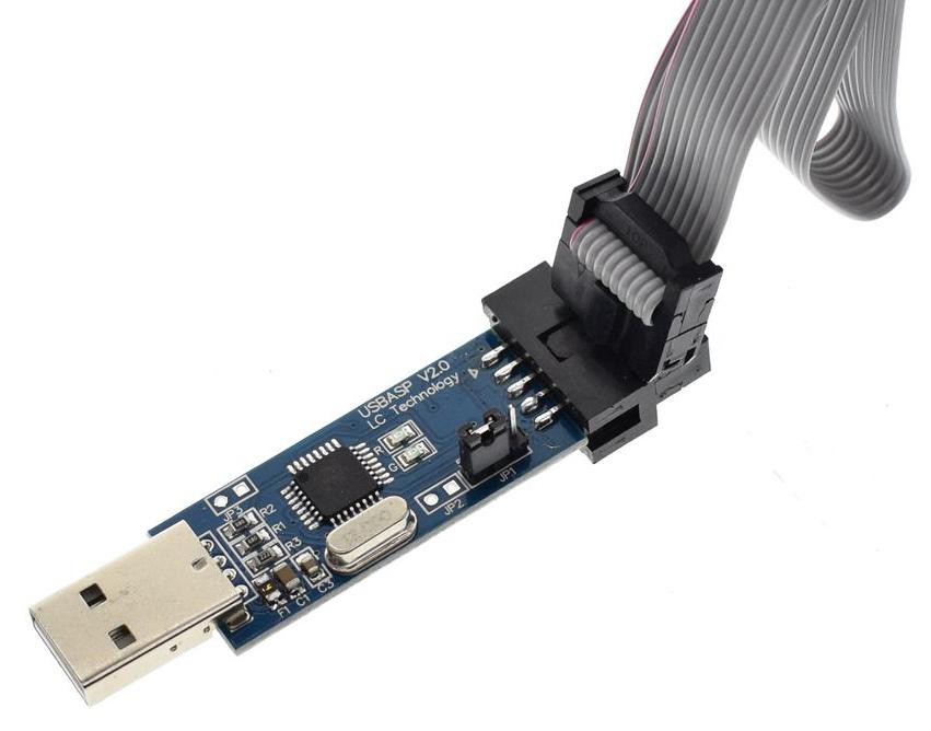
    A cheap and easy way to burn the Arduino bootloader is to use an USBasp programmer that is commonly available:

    The USBasp is also capable to give the power to the "target" using the VCC pin, but remember to check that the JP1 jumper is set to provide 5V to the target (as shown in the photo).

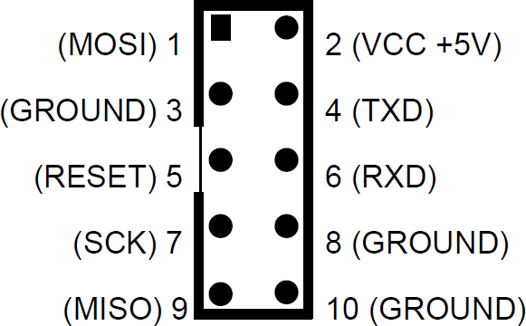
    Please note that the pinout of the USBasp is a little different from the "standard" ICSP (os ISP) pinout:


    In the previous picture it is possible see that pins 4 (TXD) and 6 (RXD) are not at GND as expected  by the standard ICSP port, and pin 3 is not NC.

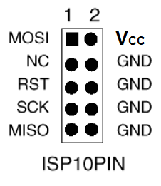
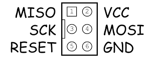
    See the following picture showing the standard 10 pin ICSP pinout:


    So you must consider this when connecting the USBasp to the 6 pins ICSP port (J3) on the Z80-MBC2 (see the schematic):

    To avoid problems I suggest to use as GND pin 10 of the USBasp connector, and connect the other pins (VCC, MISO, MOSI,SCK, RST) accordingly.

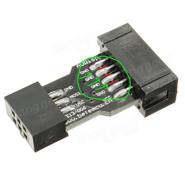
    An handy way to connect the USBasp to the 6 pin ICSP port (J3) of the Z80-MBC2 could be to use a commonly available "10pin to 6pin" adapter like this:


    but I suggest not to use it "as is" because its internal connections are done for a "standard" ICSP port, and we have seen that the USBasp connector differs from the standard one.
    The schematic of the adapter shows that isn't compatible "as is" with the UABasp connector:


    To use it is a good idea isolate the pins 4, 5 and 6 cutting the trace on the PCB of the adapter that connects those pins together, and then check with a tester.
    In the following photo are shown the three cuts (thin red lines inside the green "circle") to do:


    BURNING THE BOOTLOADER FROM ARDUINO IDE:

    To easily burn the bootloader follow these "quick and dirty" steps (tested on a linux Mint OS with Arduino IDE 1.8.5):

    STEP 1: Connect the 10 pins connector of the USBasp programmer to the 6 pins ICSP port (J3) of the Z80-MBC2 (using wires or a modified adapter as discussed before);

    STEP 2: Verify carefully that any other connector of the Z80-MBC2 is not used, and verify that both the SD and RTC modules (if present) are removed from the board;.

    STEP 3: Only at this point connect the USB side of the USBasp programmer to an USB port of your workstation;

    STEP 4: Open a "terminal" window on your workstation and go to the directory where there are the Arduino IDE executables, and get the root privileges with the command:

    sudo su

    then run the Arduino IDE with the command:

    ./arduino

    STEP 5: Because Arduino IDE is running as the root user it is necessary re-install the "core" for the Atmega32. Open the Board Manager as you already did (anyway  the guide is here). Note that you must do this step only the first time you execute the Arduino IDE as root;

    STEP 6: Now from the Tools menu of Arduino IDE select "Atmega32" as "Board", "16 MHz external" as "Clock", and "USBasp" as "Programmer". Then you can burn the right bootloader (without playing with the FUSE setting) selecting "Burn Bootloader" from the same "Tools" menu.

    All done!

View all 9 project logs

Enjoy this project?

Share

Discussions

DarS wrote 09/28/2020 at 20:29 point

Thanks for a plenty of joy with Z80-MBC2 !  I just assembled my copy and spent few evenings trying to understand the details. A kind of a user guide was crafted with all the information I could gather from different sources. If you find it useful, feel free to use/share:

https://github.com/DarS007/Z80-MBC2_guide

  Are you sure? yes | no

ermanno wrote 09/04/2020 at 18:08 point

To format the sd card I have to use fat or fat32 and what size of the allocation unit?

Or it doesn't matter.

  Are you sure? yes | no

Just4Fun wrote 09/05/2020 at 08:42 point

You can use both FAT or FAT32. The micro-SD can be a legacy one (max 2 GB if I remember well) or a SDHC. Nothing more. No others special setting are needed.

  Are you sure? yes | no

Vinicius Monteiro wrote 08/19/2020 at 00:13 point

Hey so i'm kinda noob in those stuffs (besides having a technical degree in eletronics, I never really had time to mess around with them in my spare time) and I have like a very, very limited knowledge in Arduino. How can I import a bootloader to the ATMega? Thanks everyone, and mainly for the chap who post the project.

  Are you sure? yes | no

Peter Tabatt wrote 08/04/2020 at 15:51 point

Hello,

an other day an other question. I use the hex-file S220718-R280819_IOS-Z80-MBC2... on the Atmega 32 and after starting the Z80-MBC2 i got the boot-menu. So far so good! I explored the menu-entries and after choosing Forth, I run into Forth on every reboot. How can I get back to the boot-menu at startup?

  Are you sure? yes | no

villaromba wrote 08/04/2020 at 16:38 point

Easiest way is to press both RESET & USER keys, release the RESET key holding the USER key down until the IOS led starts to blink, or you see the menu on the screen.

  Are you sure? yes | no

Peter Tabatt wrote 07/30/2020 at 17:11 point

What a cool project! It's like time-travelling for me, I feel backsituated to my time as student. My first homecomputer had a Z80-clone but no CP/M. Z80-MBC2 is a very cool project! I assembled two and they are up and running.

Now I have one question: How can I put some programs into the disk-images on the sd-card?

Is there a tool to fill the disk-images on a PC? Under Windows?

  Are you sure? yes | no

villaromba wrote 07/31/2020 at 21:45 point

If you scroll down on the 'Logs' menu you'll find  CPMtools GUI and instructions. on how to use it. (You can of course use XMODEM  to transfer files over to disk directly.)

  Are you sure? yes | no

Jonathan Guthrie wrote 07/29/2020 at 16:30 point

Thank you for this most excellent project!

I built this recently.  It works fine for me, and now I'm trying to figure out what I want to do with it.

  Are you sure? yes | no

Sigmar Roßmann wrote 07/13/2020 at 12:04 point

Hello

I am trying to compile the S220718-R260119_IOS-Z80-MBC2.ino in the Arduino studio.
If I uploaded the HEX file with the Atmel studio on the Z80-MBC2, everything works.
But the serial interface does not print any characters.

Does somebody has any idea.

Excuse my English.

greeting

Sigmar

  Are you sure? yes | no

Sigmar Roßmann wrote 07/13/2020 at 12:32 point

Hello
already solved

I had to change the HardwareSerial.cpp in one place.

  Are you sure? yes | no

Sigmar Roßmann wrote 07/06/2020 at 16:34 point

Hello everybody,


can someone explain to me what in the Arduino * ino
the 

"void serialEvent ()
// Set INT_ to ACTIVE if there are received chars from serial to read and if the interrupt generation is enabled
{ if ((Serial.available ()) && Z80IntEnFlag) digitalWrite (INT_, LOW);
} "

Interupt on Z80 is triggered?

greeting

Sigmar

  Are you sure? yes | no

Just4Fun wrote 07/07/2020 at 13:43 point

As explained in the comment it triggers the INT line when a char is ready to be read by the Z80 CPU and the INT trigger flag is enabled in the IOS firmware.

This mode is used only by the stand-alone ROM Basic.

(Not sure to have understood the question...)

  Are you sure? yes | no

Sigmar Roßmann wrote 07/11/2020 at 16:14 point

Thanks that was exactly the right answer.

  Are you sure? yes | no

ermanno wrote 06/15/2020 at 20:12 point

just4fun you're right I confused it with the pinout of the bc 557 which is inverted.

  Are you sure? yes | no

ermanno wrote 06/15/2020 at 17:20 point

The transistors 2n2907 if inserted as in the serigraphy would have the collector connected to vcc, instead it is the emitter that must be connected to vcc, therefore the flat part of the transistor goes towards the Z80 and not towards the LEDs. However inserted in one way or another they work equally. How should these transistors be inserted ...

  Are you sure? yes | no

Just4Fun wrote 06/15/2020 at 17:38 point

  Are you sure? yes | no

Stephan Kraus wrote 04/12/2020 at 20:57 point

Hi!

Thanks for the great project!

I am wondering if there is the chance to add a second serial port to hook up a printer or paper tape reader?

Best regards

Stephan

  Are you sure? yes | no

Sebastiano Grimaldi wrote 03/29/2020 at 17:51 point

I've just checked the SD card board with an Arduino uno board. I've correctly write and read file in the SD. I understand that the SD card board is working! Thanks a lot to give me some idea for additional debug. 

  Are you sure? yes | no

Just4Fun wrote 03/29/2020 at 18:38 point

If you press and release the RESET key, D11 must do a single very fast blink (also if the SD module is not present) just before the IOS SD error is "printed" on the serial port. If you don't see it there must be an assembling error/fault.

  Are you sure? yes | no

Sebastiano Grimaldi wrote 03/31/2020 at 18:17 point

Thanks for the suggestion, I've fixed the problem. Now my MBC2 is perfectly running! Best regards, Sebastiano 

  Are you sure? yes | no

Sebastiano Grimaldi wrote 03/29/2020 at 13:43 point

Very compliment for this fantastic project!

I build MBC2 everything it's working fine except the SD card!

Using the lite IOS I run BASIC and FORTRAN then the system is working.

Loading on the ATMEGA32 the IOS with SD management I got the following error:

Z80-MBC2 - A040618
IOS - I/O Subsystem - S220718-R280819

IOS: Z80 clock set at 8MHz
IOS: Found RTC DS3231 Module (29/03/20 15:34:36)
IOS: RTC DS3231 temperature sensor: 19C
IOS: CP/M Autoexec is OFF

IOS: Select boot mode or system parameters:

 0: No change (3)
 1: Basic
 2: Forth
 3: Load OS from Disk Set 1
 4: Autoboot
 5: iLoad
 6: Change Z80 clock speed (->4MHz)
 7: Toggle CP/M Autoexec (->ON)
 8: Change Disk Set 1
 9: Change RTC time/date

Enter your choice >1  Ok

IOS: SD error 2 (NOT_READY on MOUNT operation)
IOS: Check SD and press a key to repeat

There is not any activity on the LED D11, I've cheched all the route trace, no error.

Any help, please?


  Are you sure? yes | no

Just4Fun wrote 03/29/2020 at 14:21 point

That error says that there isn't any SD card inserted into the SD module...

BTW: Are you sure to have inserted the SD card module correctly (as shown in the photos)?

  Are you sure? yes | no

Sebastiano Grimaldi wrote 03/29/2020 at 17:05 point

Thanks for fast response! The sd card is correctly installed with the proper contents as per your zip archive. Best regards, Sebastiano

  Are you sure? yes | no

m.uhlmann.zwickau wrote 06/10/2020 at 06:18 point

I have also this error some times. After reconnect the sd-card or the board it works.

  Are you sure? yes | no

mikeh32217 wrote 03/25/2020 at 07:02 point

Awesome project, great fun and perfect for the era of the shutin!

Thanks for the effort!

  Are you sure? yes | no

[deleted]

[this comment has been deleted]

[deleted]

[this comment has been deleted]

Edgar Salgado wrote 06/09/2020 at 19:32 point

Hello! Any chance you are willing to sell me a spare PCB? :)

  Are you sure? yes | no

O.E wrote 02/16/2020 at 17:47 point

Hi,

After i setud circuit i connected to computer using FTDI programmer leds blinking correctly but terminal is not  open in computer when  pressing buttons.

  Are you sure? yes | no

Just4Fun wrote 02/17/2020 at 11:18 point

Hi,

have you set the sw terminal at 115200 8N1 (No HW handshaking)...? Are you sure to have connected RX/TX correctly...? An other "source" of common problems is a wrong fuse setting when flashing the bootloader first time...

  Are you sure? yes | no

wojtek.p wrote 01/13/2020 at 12:20 point

Hi,

Does anyone have 3D models (step format) for Z80-MBC2, uCom and UTerm? I want to design a 3D printing case and it would be helpful. If anyone has, please send to wojtek.p@onet.pl

Thanks

Wojtek

  Are you sure? yes | no

wenij wrote 01/12/2020 at 09:55 point

hi,

have any one knows how to build the Z80-MBC2_figforth130.asm source code?  which tools set to build?


thanks.

wenij

  Are you sure? yes | no

WestfW wrote 01/16/2020 at 23:41 point

For the MBC1, I used the TASM3.2 cross assembler for DOS/Win, which you can apparently download from: https://www.ticalc.org/archives/files/fileinfo/250/25051.html

  Are you sure? yes | no

Tony Nicholson wrote 10/12/2019 at 11:32 point

This is a fantastic little board.  I'm now starting to tinker with things a bit and I'll be attempting to combine the CP/M 3 bios modules with Simeon Cran's ZPR3 replacement BDOS routines (obtainable from the Tesseract RCPM+ archives - volume 93 at http://www.classiccmp.org/cpmarchives/cpm/mirrors/www.triton.vg/TesseractRCPM+Catalog.html#vol93 ).

Before doing this I thought I'd attempt to reconstruct the supplied CPM3-128.SYS system from sources and I'm not having much success - in particular with all the choices when running GENCPM.  Would you be able to share the build procedure and corresponding GENCPM.DAT file?  Thanks.

  Are you sure? yes | no

HerveGZ wrote 07/12/2019 at 17:08 point

Dear All

Thanks again for this wonderfull Z80 board. And sorry to start a question as beginner, but

Is there a link to a startup guide global of this board? (something detailled explain)

Even I use it yet, I  have some problems to understand the I2C (protocol I know):
In examples there are out 1,opcode and out 1, value in general is so. But as I want to add my own I2C systems (from Grove or Seeed firms) I do not understand the relation between those out 0,xxx and out 1,yyy and the I2C address (Each item has a unique one ) of my own components I2C.

Can someone thanks  to enligh me on I2C how to mbasic can i drive any component I2C added please?

Sincerely

Hervé

  Are you sure? yes | no

Just4Fun wrote 07/12/2019 at 17:31 point

Hi, opcodes are used to access to the virtual I/O devices. Read the comments in the .ino sketch about the virtual I/O engine to understand how they work (there are large comment parts in the code that are a sort of manual).

About  accessing your I2C device, this requires  changes in the FW. Some users in the FB users group have already done this to access an I2C LCD module.

You have to create new opcodes to access new I2C HW.

  Are you sure? yes | no

Similar Projects

Does this project spark your interest?

Become a member to follow this project and never miss any updates