 Alexander
Links to the other tutorials in this series:
| ESP8266 SDK Tutorial | Learn how to use the ESP8266 SDK. This is what the pros use! |
| ESP8266 Lua/NodeMCU Tutorial | A look at the NodeMCU Lua interpreter for the ESP8266. Learn how to get to Blinky! |
| ESP8266 Arduino Tutorial (You are here!) | Use the Arduino IDE to simplify development and get up to speed very quickly! |
And here's the links to the other tutorials in Part 2:
| ESP8266 SDK Tutorial | Looking at using the linker to get PWM, and the included I2C libraries |
| ESP8266 Lua/NodeMCU Tutorial | Using PWM and I2C with Lua! |
| ESP8266 Arduino Tutorial | Using the Wire library for I2C, and AnalogWrite for fading! |
Links to Part 3:
| ESP8266 SDK Tutorial | Using MQTT to develop an IoT device |
| ESP8266 Lua/NodeMCU Tutorial | Using the NodeMCU MQTT module to communicate with a cloud data service |
| ESP8266 Arduino Tutorial | We use the simpler, more widely available HTTP protocol to log data to the cloud |
Getting Help
If you run into trouble while following these tutorials, you have a few different options:
- Ask in the discussion area below the article
- Join the ##esp8266 channel on Freenode IRC and ping me (MrAureliusR) or ask anyone who is in there
- Post on the ESP8266 Community Forums (note it can take a while to get a response!)
- Send me a private message here on Hackaday
The ESP8266 has been popular for quite a while now. The low cost of getting a module coupled with its power and reliability has made sales of the chip shoot through the roof. There's a lot of resources out there, but I wanted to combine all that information together into one place. So let's get started!
The ESP8266 was designed by a Chinese fabless semiconductor company called Espressif. Fabless means they just create the chip design, and they get another company to actually manufacture the silicon (Atmel was also a fabless semiconductor company). While having Wi-fi on-chip with a microcontroller was not a new idea, the concept having a simple serial link to control it out of the box was. Hobbyists all over the world started playing with the chip to see what it could do. Without having to program the ESP, complex IoT applications could be developed, using the ESP simply as an external Wi-fi chip. This is the easiest method for those who don't have interest in diving into the ESP itself. You can use AT commands over a serial link to control the chip. This is the only way to control the ESP modules which only have 8 pins. A full list of the AT command set can be found here. This is a perfectly acceptable solution for many hackers, and if that's all you need then great! I built a data-logging module which used the Sparkfun phant server as the backend using only AT commands. Getting it connected to my Wi-fi network and sending data was very easy.
However, many of you are here because you want to dive deep down into the power at the heart of the ESP8266. You want to program the module using Arduino or the SDK. You are interested in playing with Lua and discovering how it can be used in an embedded system like this. I generally recommend that people new to the ESP8266 buy a pre-fabricated module from a company like SparkFun or Adafruit.
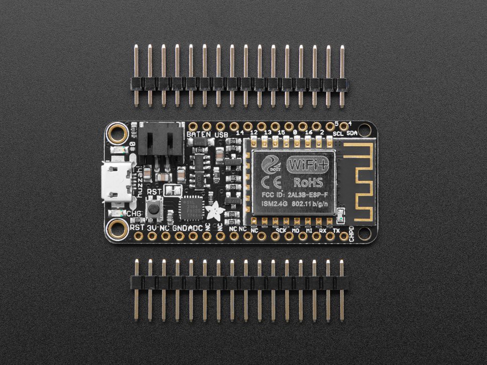
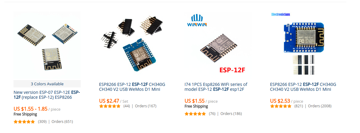
This takes a lot of the difficulty out of spinning your own board. But if you want to spin your own board using, say, an ESP-12F module, here are a few tips (skip to the tutorial section if you bought a HUZZAH Feather or a SparkFun Thing, or similar):
- Decide which module you want to use. The modules were originally designed by a company called AI Thinker, but now have been widely cloned. Some of these have on-board 3.3V regulators, others don't. Take some time to find a reliable source, and take a close look at the requirements for the board. The cheaper boards tend to require more external components, while the more expensive ones have them built-in, so it's up to you to decide what is more important.
- If you are designing your own breakout board, make the pads on your PCB nice and big. This makes soldering the castellated pads much easier to do by hand. Or, if you are using 0.1" headers, which some of the modules support, make sure to think about the outline of the board. How high will it be above the PCB? Do I need to move capacitors/other tall components out of the way?
- There are breakout boards that you can get from the usual suspects for incredibly low prices. These are great for development and testing.
- ESP GPIO pins 6-11 cannot be used, as they are reserved for talking to the flash chip. Be mindful of this, as trying to control those pins will probably just crash the chip! In some modules, pins 9 and 11 are available because the module uses a DIO flash chip, instead of QIO (double data rate instead of quad data rate). Double check before using these pins!
Great, so you've got your modules, and you are designing your PCB. In order to program the ESP, we need to keep a few things in mind. You'll need a USB-to-serial dongle to program it. Make sure to get a 3.3V model, or one that is switchable. 5V will fry the chip. These are a dime a dozen, and can be found at all the major suppliers. FTDI are very reliable, but many hobbyists have avoided them after FTDI-gate. The two cheap alternatives are the CP210X and the CH340. Both work fine, though some users report stability issues at high speeds with the CH340. Connect the TX from the ESP8266 to the RX of the USB-to-serial board, and the RX of the ESP8266 to the TX of the USB-to-serial board. Make sure to also connect the ground, and if the module has a DTR connection, add that if it's available. This will auto-reset the chip after upload.
Additionally, we need a few more resistors to tell the module what to do on power-up. There will be a pin, variously labelled as CH_PD (chip power down) or CH_EN (chip enable). This needs to be connected to VCC via a pull-up resistor (anything in the range 4.7k-22k should be fine). "Normal" boot mode is selected by pulling GPIO0 down to ground with the same value resistor you used for the previous pin. Add a third resistor of the same value to GPIO15, also pulling it to ground, to disable SD-card boot mode (it tells the chip to boot from Flash, which uses slighly different timing and protocols). GPIO2 also contributes to this selection, but that pin's internal pull-up is automatically enabled at boot. Just make sure that none of your external circuitry affects these pins at start up, or you could end up in the wrong boot mode. In my head, I basically just ignore these three I/O pins unless I absolutely need another GPIO. GPIO2 is the easiest to use, as after boot you can safely disable the internal pull-up.
Let's take a look at a chart showing what the different combinations of GPIO at boot will do:
| GPIO0 | GPIO2 | GPIO15 | Mode selected |
| 0V | 3.3V | 0V | Bootloader mode (UART) |
| 3.3V | 3.3V | 0V | Boot from Flash |
| D/C | D/C | 3.3V | Boot from SD card |
D/C: Don't care
So, to get into bootloader mode where we can program over the UART, we must boot with GPIO2 high (which it will do on its own because of the internal pullup), and GPIO0/15 low. This can be accomplished by adding either a button or other circuitry to pull GPIO0 down to ground. When the button is released, it will boot from Flash as normal. To boot from an SD card, which is a feature that hasn't been widely documented and which we won't cover here, pull GPIO15 high at boot (it ignores GPIO0/2 in this state).
How does the Feather HUZZAH reset circuit work?
One of the many reasons for using a development board over the raw modules, especially in the prototype phase, is the little features to speed up your development process. The Adafruit Feather HUZZAH has an automatic reset circuit on it. Two transistors and two resistors make up the circuit. Let's take a look at it:
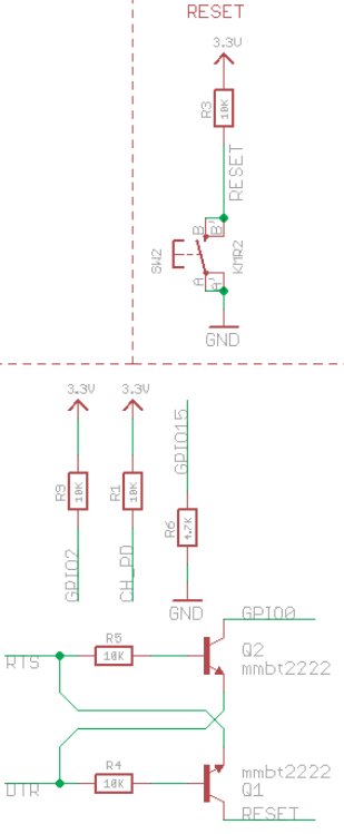
I was baffled by this circuit at first glance. If we assume both RTS and DTR are low, then neither GPIO0 nor RESET are affected. If DTR is brought high, Q1 turns on and pulls RESET low to reset the chip. Alternatively, pulling RTS high will pull GPIO0 to ground. However, I couldn't understand how to get both to happen at the same time. If you were to pull both RTS and DTR high at the same time, you could potentially end up with more than 3.3V on GPIO0 (this is a complicated subject that I won't cover here).
My first clue was in esptool.py. This is the tool that is used to program the ESP8266.
""" Try connecting repeatedly until successful, or giving up """
    def connect(self):
        print 'Connecting...'

        for _ in xrange(4):
            # issue reset-to-bootloader:
            # RTS = either CH_PD or nRESET (both active low = chip in reset)
            # DTR = GPIO0 (active low = boot to flasher)
            self._port.setDTR(False)
            self._port.setRTS(True)
            time.sleep(0.05)
            self._port.setDTR(True)
            self._port.setRTS(False)
            time.sleep(0.05)
            self._port.setDTR(False)
...
So it pulses RTS high (pulling GPIO0 to ground), then pulses DTR high while pulling RTS low, then pulls DTR low as well. What happens is complex, but it comes down to the order of the second two instructions. We pull RTS down after we have started pulling DTR high. So for a brief period of time, the chip will be in reset with GPIO0 low, which is the trigger to enter bootloader mode. Pretty incredible!
Why is the ESP8266 so inexpensive?
What are the three major components of most chip makers? Hardware (silicon development and manufacturing), software (writing drivers, APIs, and example code) and support (engineers and support technicians available to help via phone, email, and forums). If you want to make a chip cheaper, then you need to cut back in all three areas as much as possible without sacrificing usability.
Many other companies, including TI, Cypress/Broadcom, and Realtek, make wi-fi enabled microcontrollers. They are more expensive, and are typically used in consumer devices where reliability and ease of development is needed over cost. This explains why Android phones haven't all switched to using a cheap wi-fi chip like the ESP8266. The SDK is passable, but far from ideal. The documentation is iffy and incomplete. While there has been a huge community effort to close these gaps, many companies don't want to gamble on a relatively unheard-of company like Espressif, and choose instead to go with proven companies like TI, Broadcom, etc. This is why the ESP8266 is so inexpensive: Espressif wanted to compete with cost. They did just enough to make it usable, and not much more. The chip itself also has fewer features, such as no DMA, no hardware crypto module, single-channel ADC instead of multi-channel, etc. There's nothing inherently wrong with this model; on the contrary, ESP8266-based devices are appearing everywhere. But you won't see them in routers, or smartphones, or anything where development speed and reliability is more important than cost.
When you are paying your developers to make a product, you don't want them banging their heads against the wall, trying to figure out the idiosyncrasies of a particular chip. You want them to be able to pick up a phone or send an email, and talk to an applications engineer who knows your application and has likely seen your issue before. You want them to be able to use tested hardware features, instead of trying to implement things like crypto in software. This is what you're getting when you pay the extra $4-8 per chip. Take a look at the datasheet and documentation for, say, the TI CC3200. The datasheet is 71 pages; compare that to the ESP8266's 28. The ESP8266 has a Technical Reference manual of 117 pages; TI's? 572. Some of the links in the ESP document lead to 404 Not Found pages. When you are spending many hours of your life getting to intimately know a chip, you need to have all the info at hand. You don't want to spend hours digging through forums and GitHub comments trying to track down some strange issue.
However, the ESP8266 is a great chip. It has found a niche in the hobbyist market for sure, and we are likely to see more and more IoT devices using it or a derivative. The cost makes it attractive -- almost disposable for prototyping and hobbyist applications. Going back to our comparison with the CC3200: it is $16.26CAD in individual quantity on DigiKey (about $12.50USD), or roughly half that if you buy a reel of 2500. The ESP8266 is $4.13CAD ($3.18USD) and it drops to $1.96CAD ($1.51USD) on a reel of 1000. So it's a quarter of the price in individual quantity, and an eighth of the price in bulk (probably even less once you get to 2500 or 10000). This is Espressif's huge advantage, and why I am sitting here writing this right now! I do have to repeat that the CC3200 has many more features, which drives up the price, but if you don't need to run an RTOS or have critical infrastructure depending on it, then the ESP8266 starts to make more sense.
Even if the official documentation is spotty, a huge network of hobbyists and professionals has sprung up to offer community support, trade hacks, and write completely new firmware for it. NodeMCU and Arduino are the biggest examples of this. Having those two tools available set the hobbyist market on fire. Right when the ESP8266 was starting to spread, I was qualifying a wi-fi chip for a project. I seriously considered using the ESP8266, but when I took a look at the documentation, I knew it was more trouble than it was worth (especially at that stage in the project, and considering at that point documentation was still fairly sparse). I ended up going with the TI chip. Now, however, the decision wouldn't be quite so simple. If you can put in more engineering time and cut your BOM by $6-7USD, it might make sense to use the ESP8266 instead. That choice is, of course, left to the reader. I hope these tutorials help you get started in the wonderful world of ESP!
Summary
| PROS | CONS |
| Cheap, readily available, many dev boards with documentation | Difficult to use interrupts, most user code has to be timer or task-based |
| Compatible with Arduino, NodeMCU (Choice of languages: C, C++, Lua) | Strange ADC input range of 0-1V, and only single channel |
| Lots of libraries available, quick prototyping | I2C done in software, not hardware, so it blocks while communicating |
| Only 3.3v, no crazy voltage requirements | Requirements to enter sleep mode can be confusing |
| Mostly open-source SDK, with GDB | Watchdog timer, so user tasks cannot exceed a certain amount of time |
| Large online community, with lots of tutorials (like these!) | Serious RAM limitations in certain configurations means code needs to be carefully optimized |