Plasma speaker – exploring unusual properties of plasma
During the study of properties of ionized gas, a plasma speaker set is used, which had been built by the author. The original application of plasma recreating music refers to the year 1946 and inventor Siegfried Klein, who patented it in 1946.
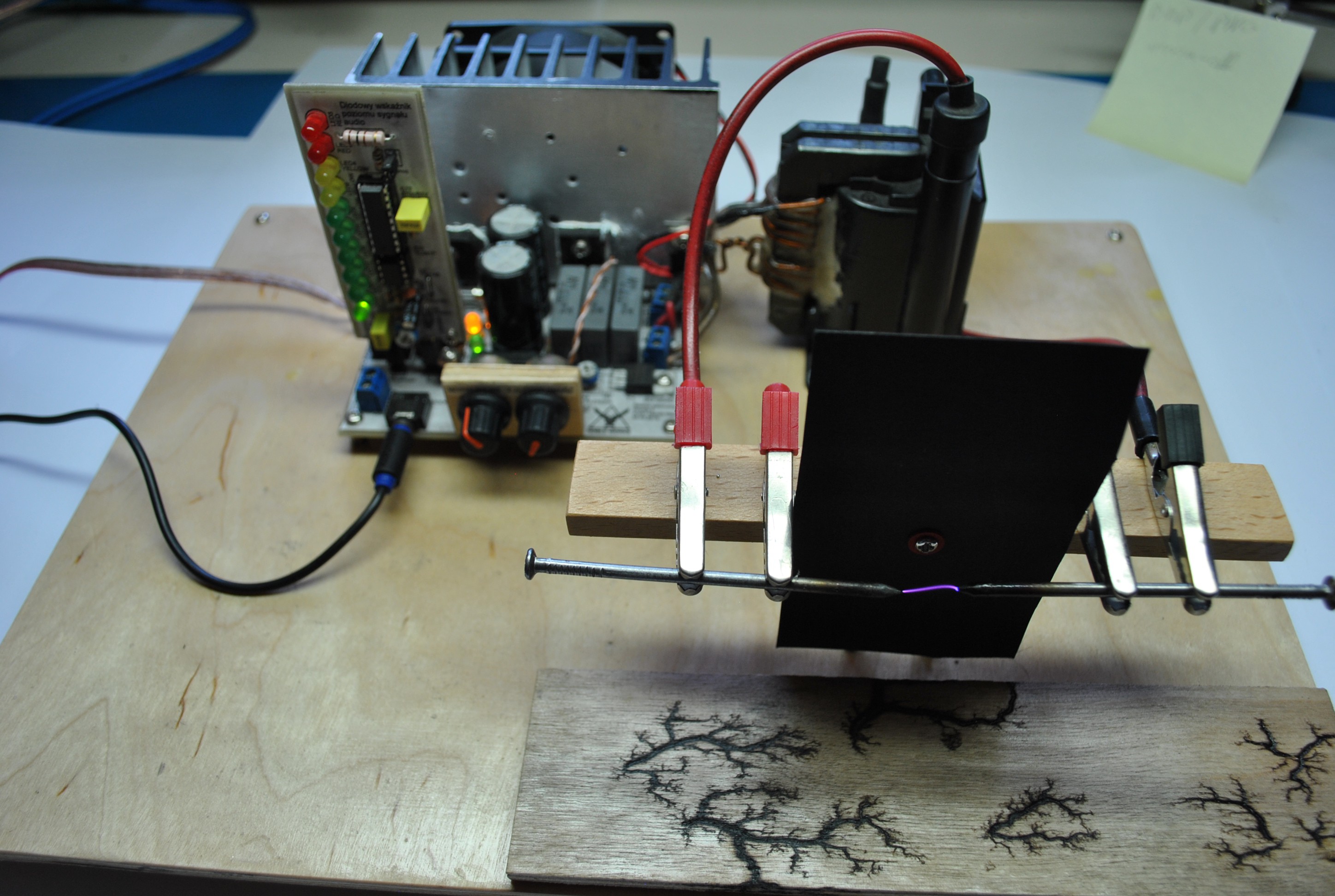
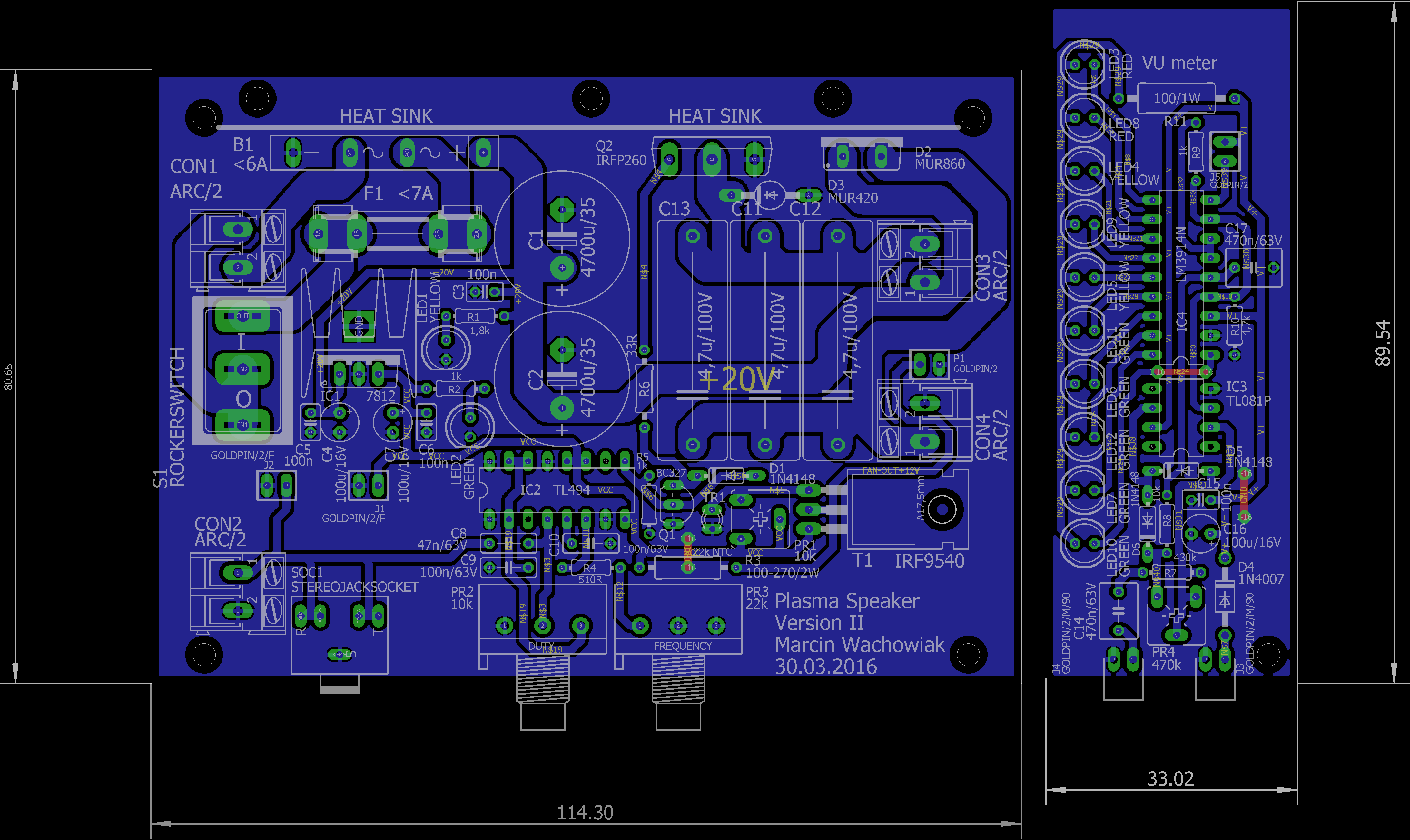
The electronic circuit has been accomplished basing on commonly uploaded projects of this type, without any precisely mentioned author. Before designing the scheme and the circuit board the constructor decided to support himself with the advices and experiences of other designers. This resulted in introducing new solutions improving the performance of the speaker. After the analysis, he designed a schematic and a circuit board in Eagle CadSoft. The last stage was to mount everything on an exposure board, to test it and carry out little repairs. Whole project has been carried out in the home workshop of the creator using collected materials and acquired experience in electronics.
The order of activities examining and describing the properties of plasma came up as a result of observation of different phenomena affecting plasma. In the experiment included were also interactions of everyday objects with plasma which came across as a result of search. Carried out to enrich the form of presentation to deliver as much information about plasma and its forms as possible.
WARNING! During the experiment a device generating high voltage and ozone is used. It may pose a threat to health or life of the users. It must be performed by an experienced or mature physician or student who will avoid any dangers. The user carrying out the experiment must be very cautious.
Before attempting to perform the experiment, we must have the basic knowledge about plasma and physical phenomena concerning it. This will help us understand the processes and physical laws ruling it better.
During the experiment important will be the concepts of:
- Cold plasma - highly ionized gas (conducting current), due to its’ specific properties is called the fourth state of matter. It is a cloud of gas electrically neutral, with a high concentration of electrons and ions. It is present in relative low temperatures and pressures.
- Electrical discharge – flow of current through an isolating environment due to very strong electromagnetic field (very high voltage)
- Electric arc – a continuous electrical discharge in normal conditions
- Fluorescence – a phenomena of emitting light by an excited (mostly by light) atom or particle
Necessary is also the acknowledgement of basic physical phenomena like:
- Creation of an acoustic wave
- Definition of a flame
- Magnetic interactions and magnetic field properties
- Optical spectrum
- Ionization of gas in energy-saving light bulb
- Rule of transformer and it’s ratio
To carry out the experiment is needed:
- Plasma speaker circuit with electrodes - used as plasma source
- Regulated laboratory voltage supply - providing the power needed for the set
- Source of sound signal ex. MP3 player
- A candle, ferrite magnet, probe of tonic containing quinine, whole piece of spiral energy-saving light bulb bubble, simple Jacob ladder made of wire
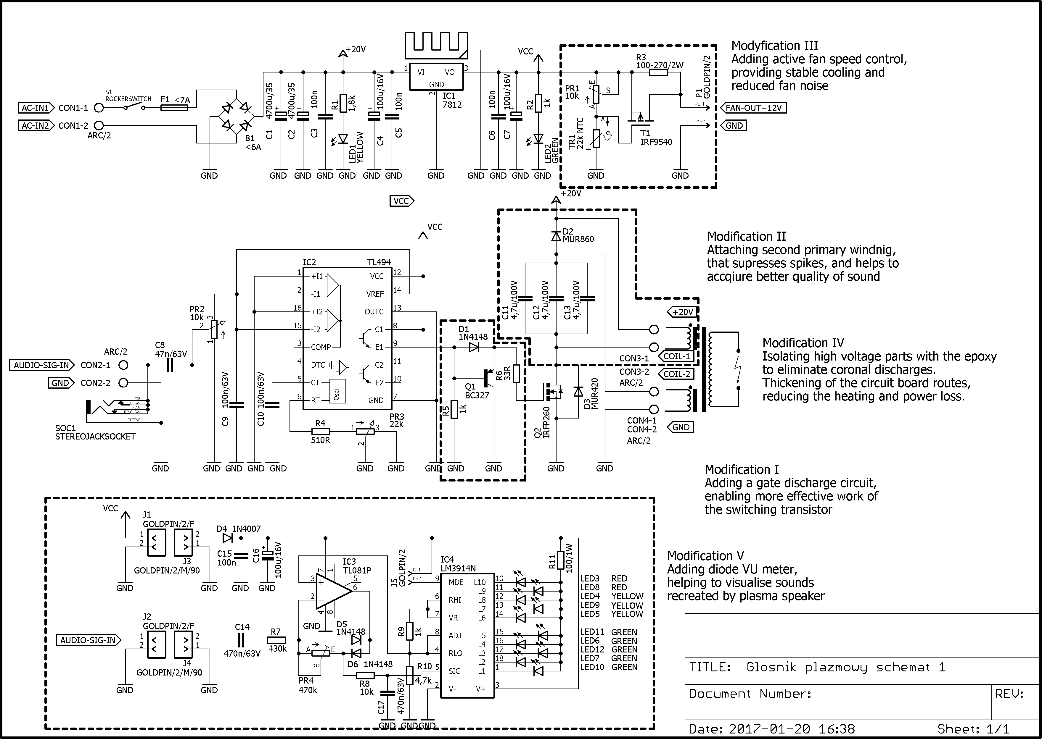
To understand in what way the high voltage appears at the electrodes and electric arc is produced, we need to analyze the circuit and determine the functions of each block. After simplifying, that means omitting the inessential minor circuits like filters or signalization devices the oncoming analysis is much easier.
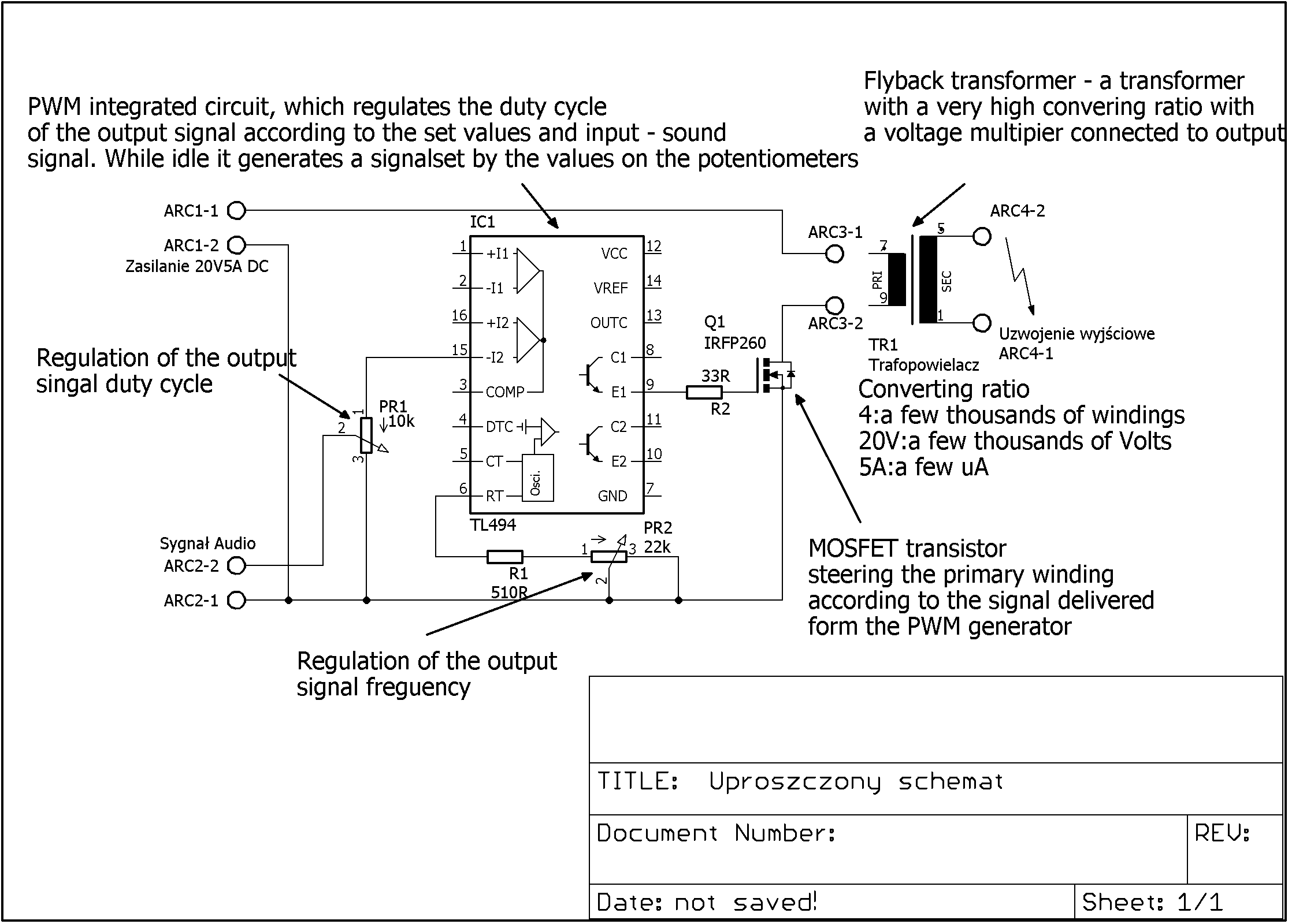
The device works in a a folowing way: in the idle state the PWM generator produces a square wave signal with a defined length time and frequency, which are set by potentiometers. The signal generated by the integrated circuit is delivered to the gate of a switching power MOSFET transistor. At the transistor the small signal is processed into adequate in properties high current pulses, which are provided by the power supply to the primary winding of a modified flyback transformer. As a result at the secondary winding appears very high voltage, mutliplied many times because of the very high flyback transforming ratio. The transformer output is connected to the electrodes. Between them a very strong magnetic field is created. This causes the ionisation of the air between the outputs and allows the current to flow through it creating a stable electric arc – our source of plasma flame.