This project has two main electronic parts: one is an Arduino micro-controller board (pretty much any model will do) and the other one is an optical switch we control by puffing or sucking into a small cavity with a membrane at one end.
For prototyping purposes we used an Arduino Mega 2560 just because it was handy.
If we actually want to emulate a keyboard and a mouse we will likely use a small Arduino Leonardo variant.
We've been wondering for a long time how we could make a switch that's easy to make and use without spending a lot.
We think we got to a pretty good solution that has only one moving part, and some cheap electro-optical components.
The Film Canister
The Cap (We use two of them)
The electro-optical components are an IR (Infra-Red) LED (Light Emitting Diode) and an Opto-Transistor obtained from a cheap "QRD1114" Optical Detector.
Normally the LED and Opto-Transistor are held by a shell and point in the same direction. If they are facing a nearby reflective surface and the LED is powered up, the IR "light" will be reflected onto the Opto-Transistor which will start to conduct.
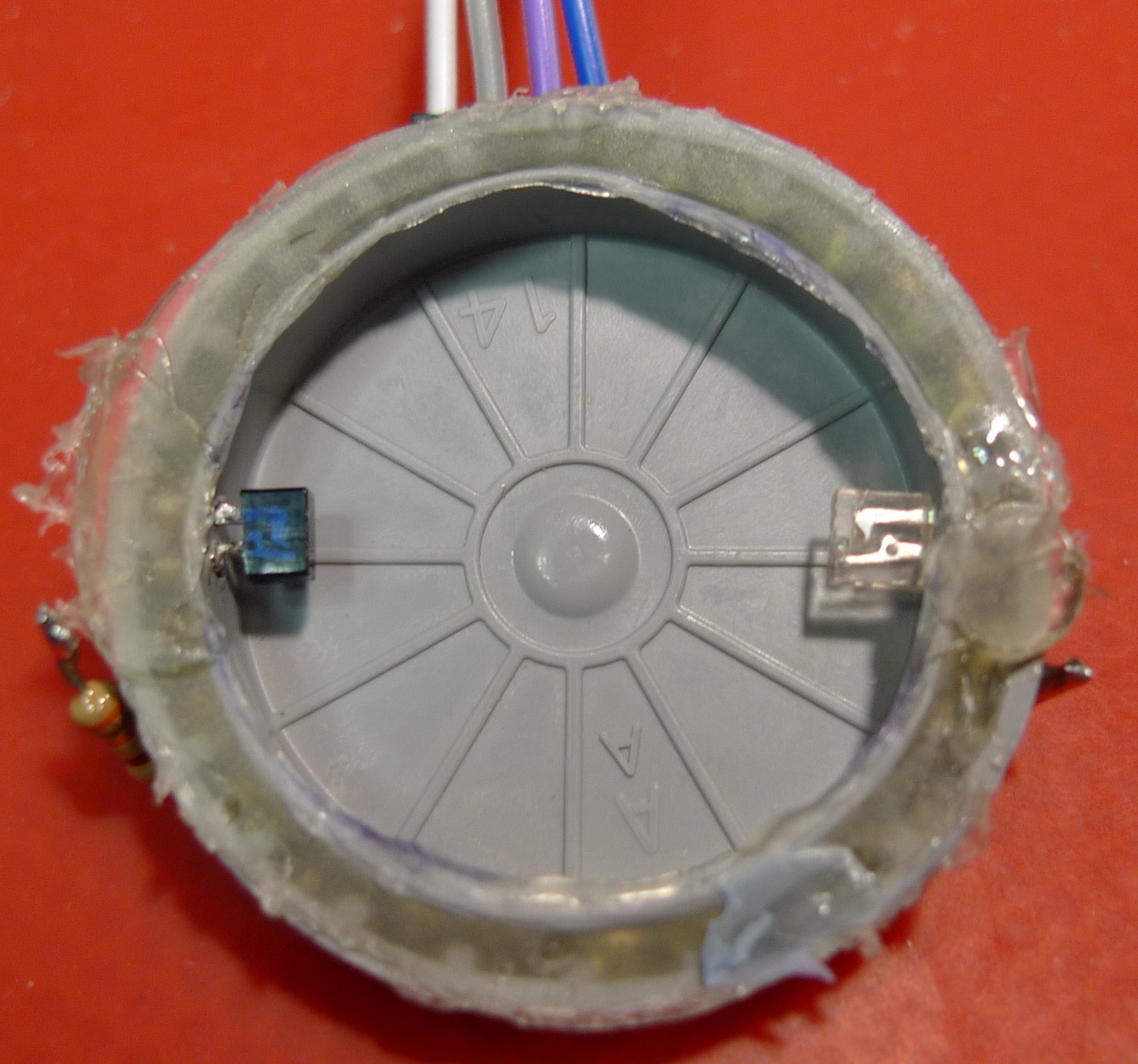
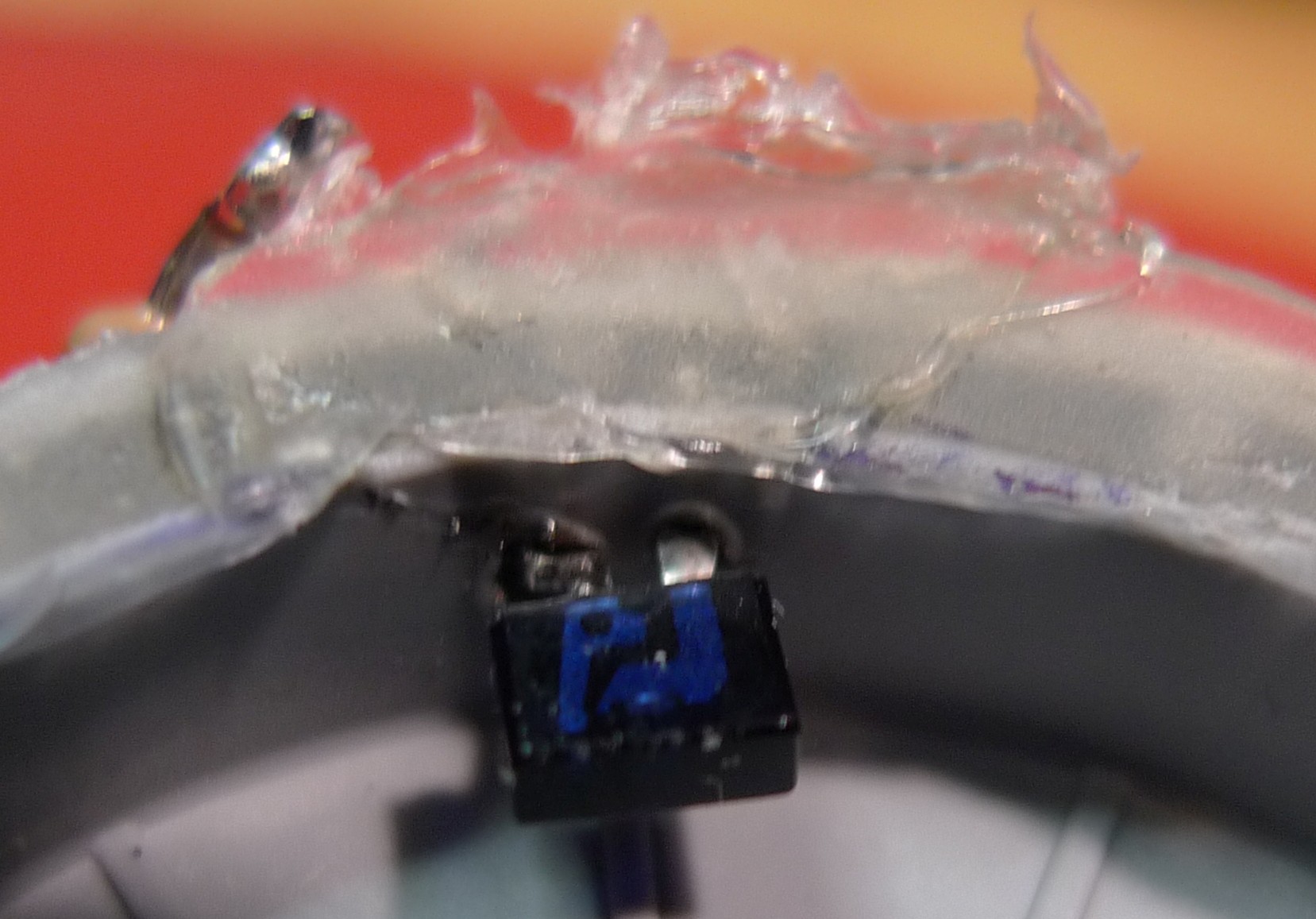
In our case we removed them from the holding shell and we placed them on opposite sides of a film canister cap so that when the LED is powered up the IR "light" shines straight onto the Opto-Transistor, unless the membrane gets in the way.
We place one pair on each side of the membrane so one is blocked when we puff and one when we suck.
The moving part is a membrane cut from a rubber glove (could use a balloon) and is loosely glued onto a the open side of a film canister cap, but not before the LED and the Opto-Transistor are placed inside, pins pushed through the walls of the canister cap, while being heated with the soldering iron.
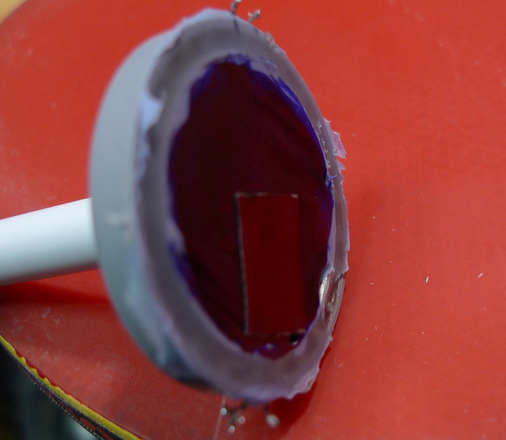
One of the caps has a hole and a tube connected to it with hot-glue. The tube is from a pen, but some arrangement that gets rid of saliva should be connected to it (this is a prototype for testing feasibility :-)
This didn't work at first because the membrane wasn't opaque enough to the IR, but two pieces of duct tape fixed that (the black permanent pen we tried first wasn't enough).
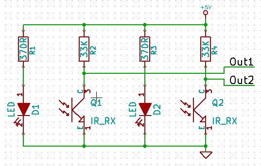
The schematics for the switch also contain some resistors to get the right current through the LEDs (we chose just above 10mA) and pull-ups for the Opto-Transistors' collectors.
Out1 and Out2 are normally Low because the IR "light" can get to the Opto-Transistors therefore keeping them "open" so they pull the outputs to ground.
When we suck or puff through the tube, the membrane is pulled or pushed and blocks one or the other light paths therefore closing one of the Opto-Transistors so that output will go High.
The outputs get connected to two digital inputs of the Arduino.
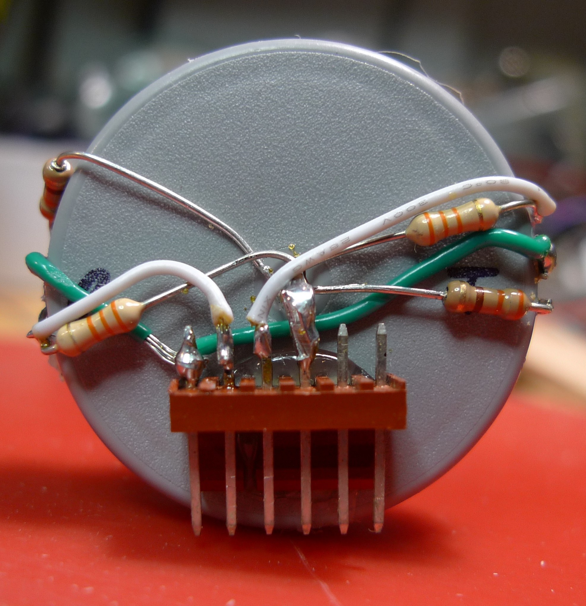
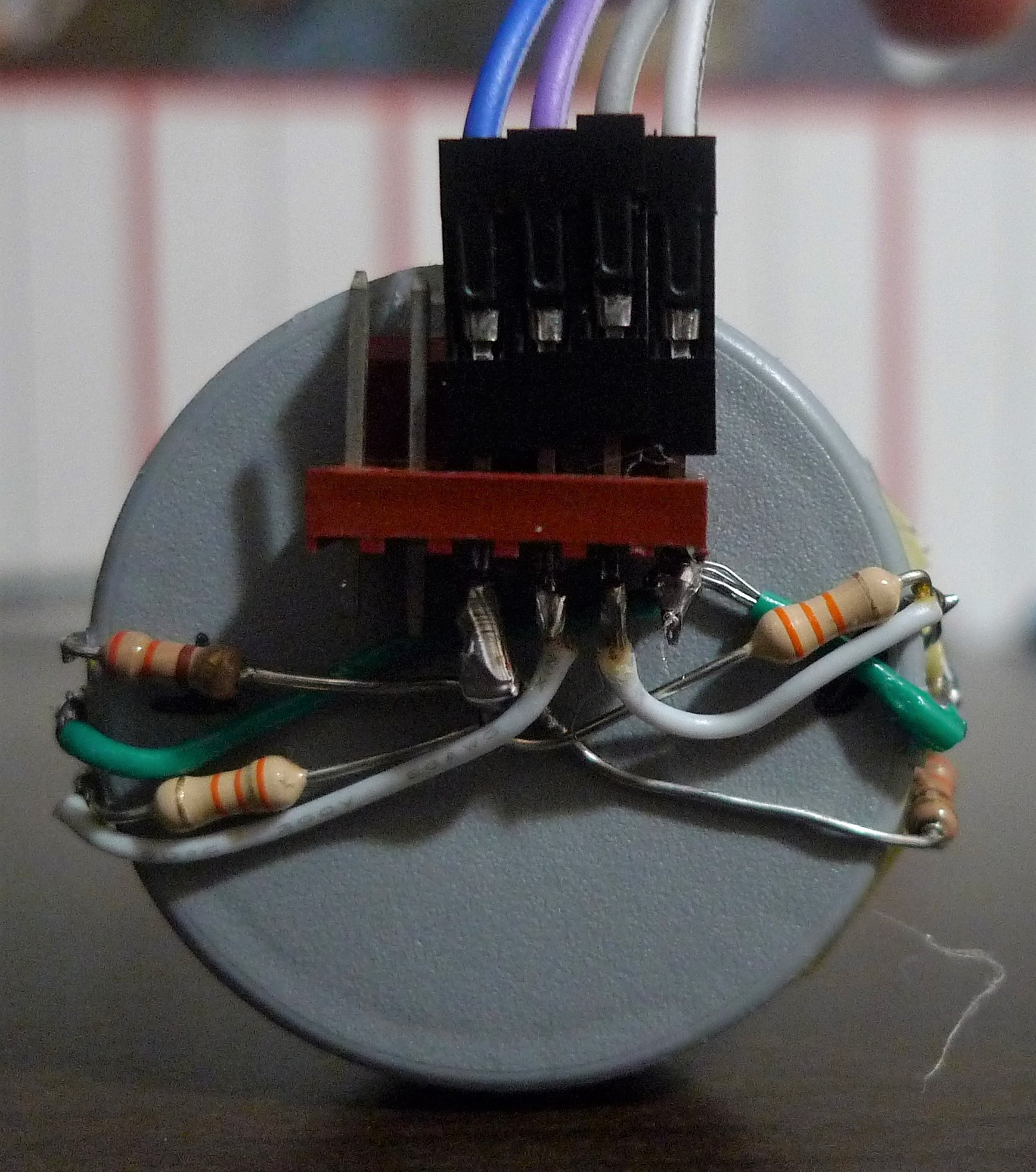
Here you see a very ugly but functional implementation of the above schematics (with 330ohm resistors instead of the 370 shown in the schematics):
Enough for today eh?
2
Get the Code
You can get the code at our GitHub repo, and alter anything to your content.
The method we used to translate Morse to text was taken from this website.
For each character, we have a start bit (1) and add 0s for dashes and 1s for dots. Let's take Q for example.
dash dash dot dash
becomes
10010, which when translated into base 10 becomes 18, which is why in our array
the letter Q appears at index 18. Lower down in the code we also have some punctuation detection for numbers larger than 63.
You may edit the code to your heart's content! Just remember to copy the licenses if you want to redistribute it :)
3
Connections
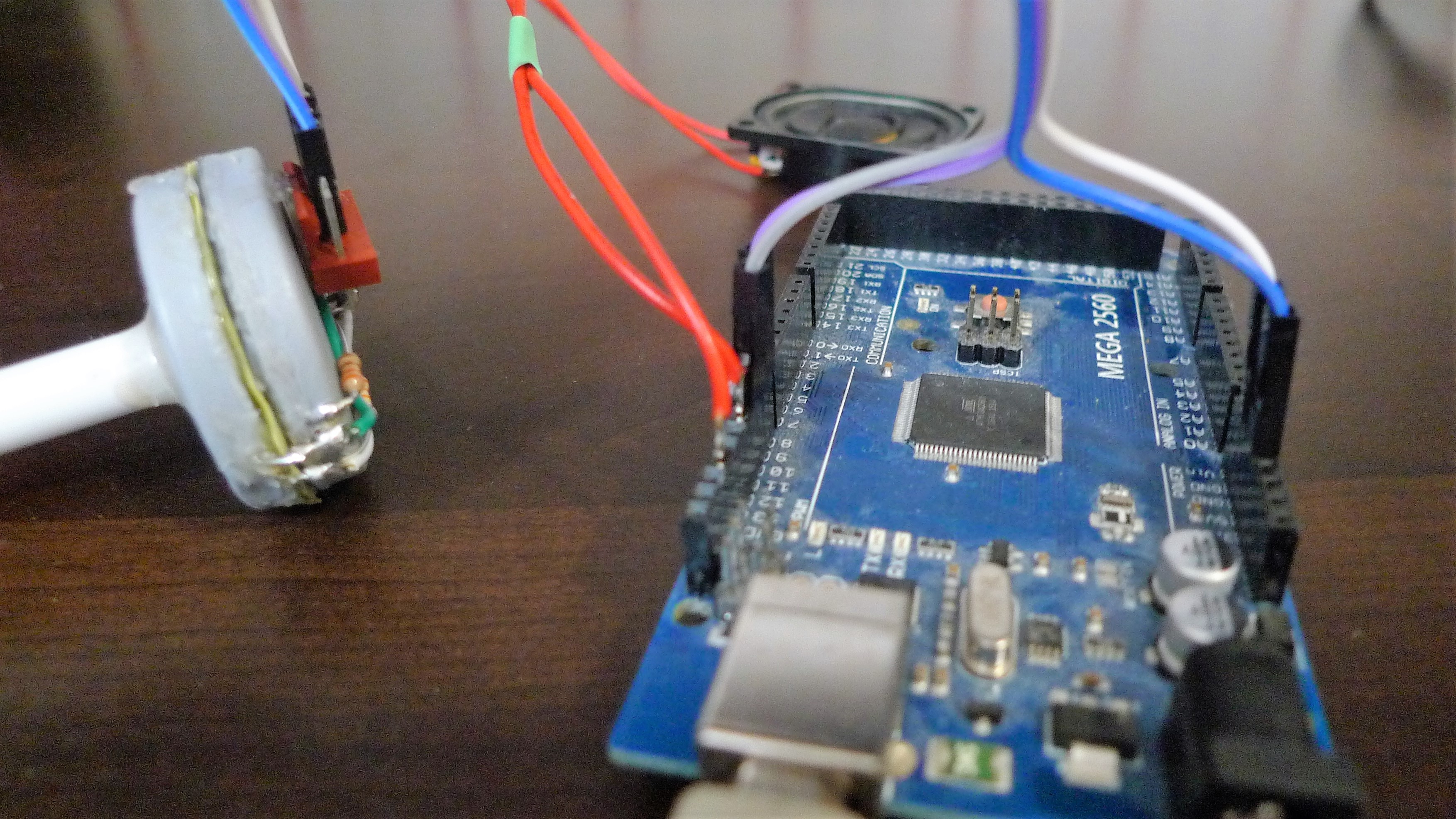
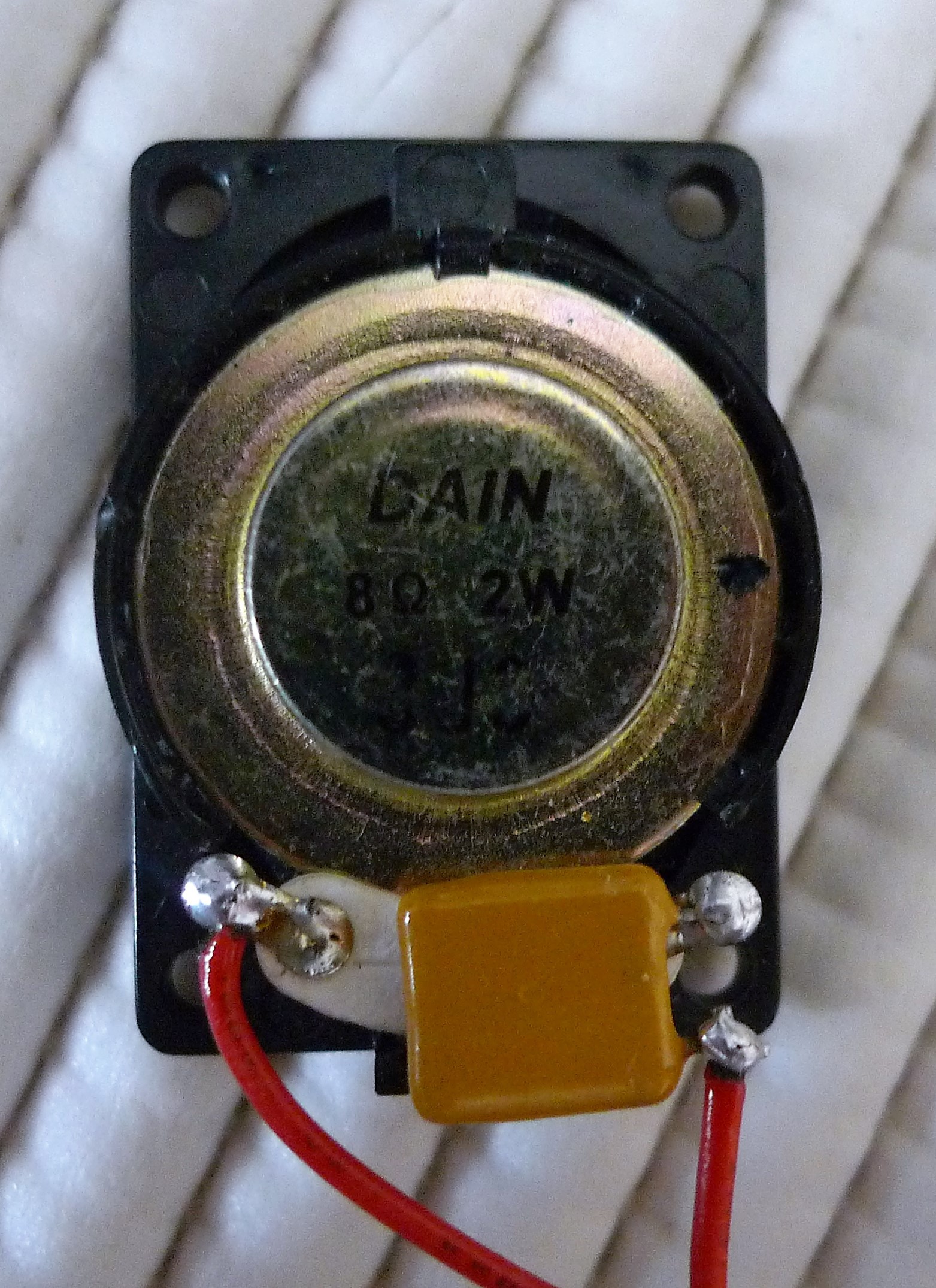
Finally, it's time to connect the Puff-Suck tube to the Arduino. We're also connecting a speaker since it's pretty difficult to Morse without hearing the signal.
This is our current (very rough, but working) setup:
Here are the connections to the tube:
Cat soldered a capacitor onto the speaker to prevent the speaker from getting the full 5 Volts and perhaps breaking..
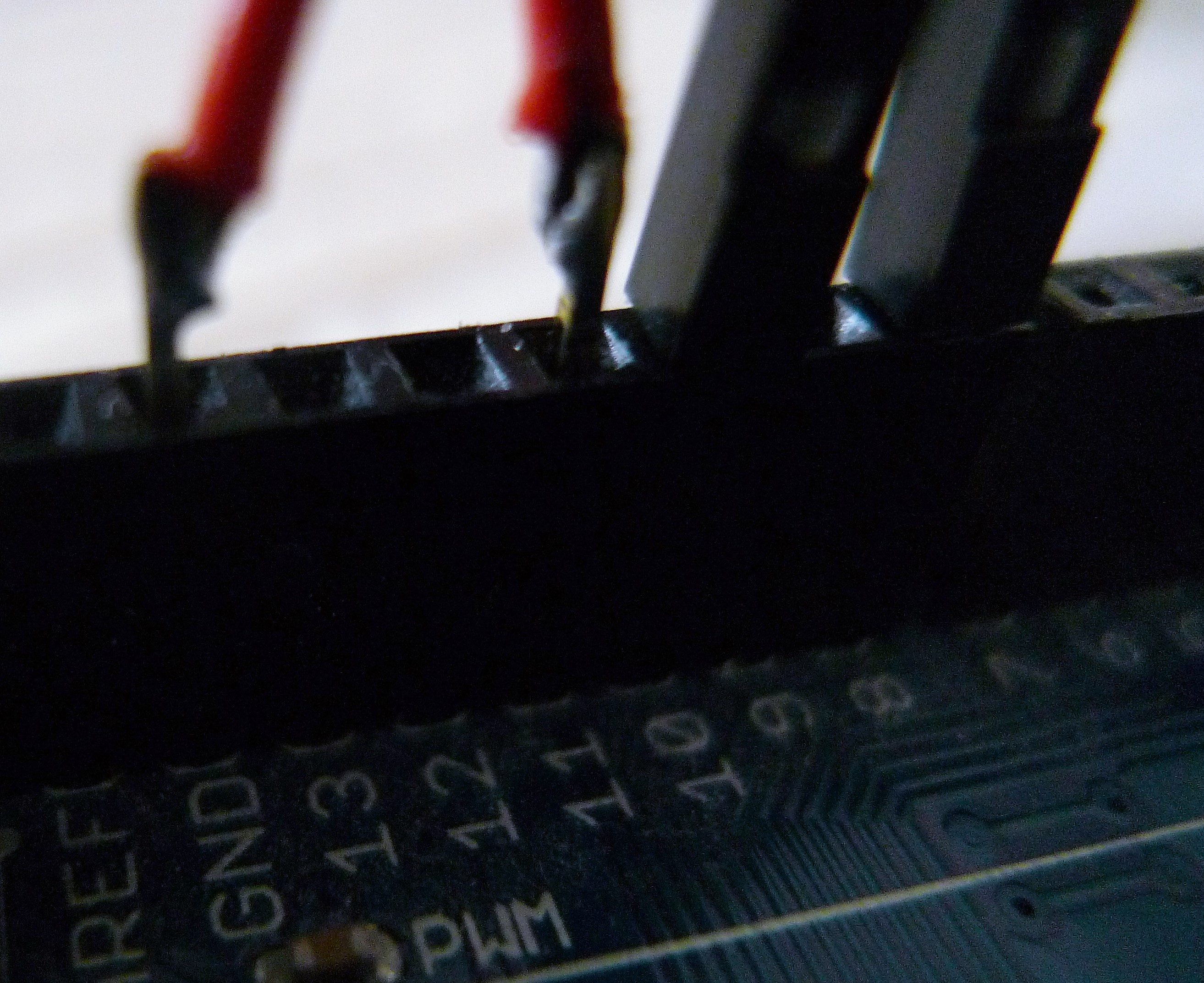
The speaker is connected to pin 11 and ground on the Arduino, and the Opto-Transistor outputs (grey and purple wires) you saw in step 2 are connected to pins 8 and 10 (you can switch them to switch what each signals).
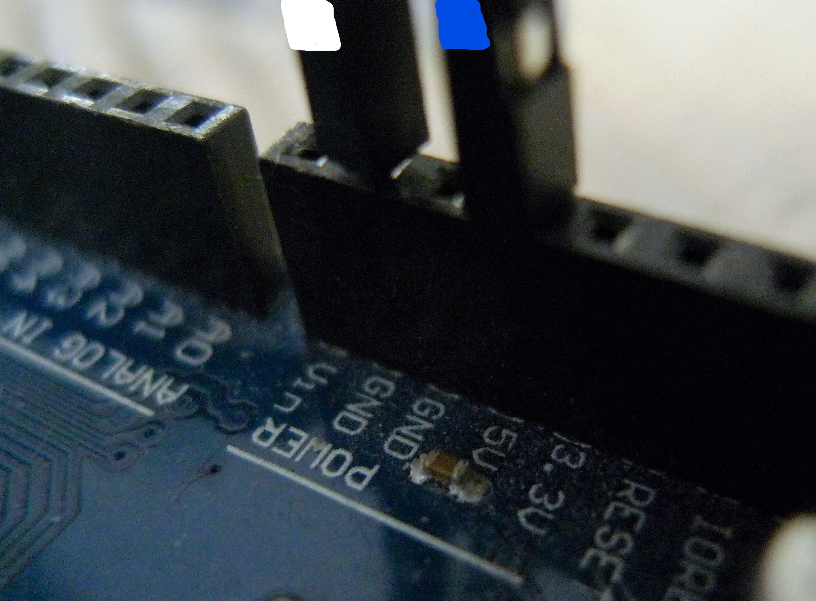
And the power to the tube is provided by 5V (blue wire) and ground (white wire) on the Arduino:
If you would like further detail on the instructions (or anything else for that matter), don't hesitate to ask in the discussion.
 Ana
Ana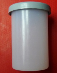
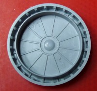 The Cap (We use two of them)
Discussions
Become a Hackaday.io Member
Create an account to leave a comment. Already have an account? Log In.