 Stephen Tranovich
Okay, let's get this chat started!
 Yay!
Yay!
 A big welcome to @Carl Bugeja for joining us on the chat today to talk about their PCB Motor designs!
 Thanks for having me
@Carl Bugeja , kick us off by telling us a little bit about yourself!
So my name is Carl Bugeja. I'm a 23yr old electronics engineer, graduated from uni 2 yrs ago and since then i've been trying to build cool robots
Sounds like the dream to me.
Our first question comes from @Lutetium : Where did the inspiration for your PCB Motor design come from?
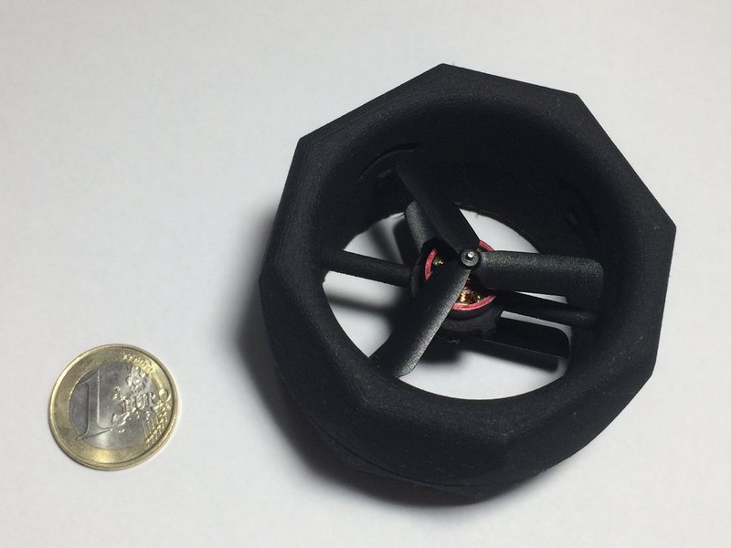
I had this drone startup were we were trying to design a very tiny coaxial drone.. we have failed because we were trying to use off-the-shelve parts to integrate it into our drone.. after this i had come up with the brsuhless pcb motor concept were i was aiming to combine the prop, stator and electronics driver into one unit
Haha i guess that answers the question
Hehahe It totally looked like you were the fastest typer on the planet!
this is the drone
Wow, awesome! I see the PCB Motor in there. Any videos of it flying?
 doesn't look like it can fly stable with only 2 rotors, e.g. the Tiny Whooper has 4
this was actually before i came up with the idea of the pcb motor.. so this robot has an off-the-shelve brushless motor.. It had four tiny flaps that control the roll and pitch axes but that's were we failed as the flaps were too small to create a strong enough force to move the drone
![]() You just very precisely identified the design problem, so isn't that fixable ?
You just very precisely identified the design problem, so isn't that fixable ?
at that time we had given up.. this robot weight under 30 grams and it was very hard to go lower than that
only one prop? the whole thing must spin like crazy :-)
 the duct has a second fan in it
if you look closely
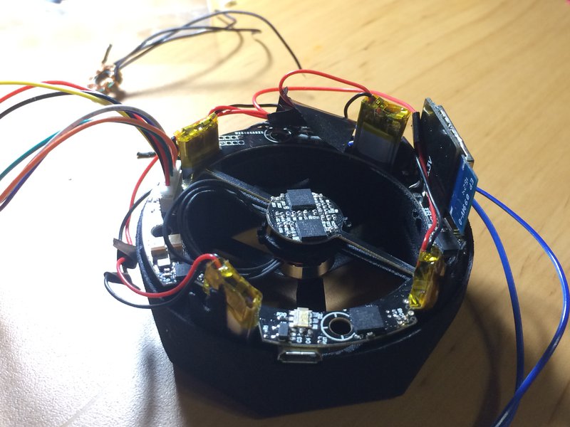
no it has two props rotating in opp direction to control the yaw.. this is the pcb as you can see it is really packed and that dual brushless motor driver in the middle inspired me to try and design the pcb motor
 Are pcb motors more efficient than off-the-shelf brushless motors?
 the magnetic fields of the 2 solenoids will not interfere when they are so closely packed?
I mean on the PCB dial motor design
my current prototype of the pcb motor is coreless so you cannot actually compare it with the off-the-shelved ones as they have an iron core.. so efficiency-wise it is not but it is much smaller and cheaper to assemble and manufacture
Where has the design of the PCB Motor left this tiny drone project?
And then we'll hop into some more community questions, because we have some juicy ones waiting.
Please show us what a pcb motor looks like and describe how it works...
@Kris Winer here is the project page for the PCB motor: https://hackaday.io/project/39494-pcb-motor
Thanks!
You're welcome!
Okay, the next question is by @Jarrett : Ever consider doing a multi-pcb stackup? Or aluminum substrate?
So in this startup drone project, i was not alone.. but i was responsible for the hardware design. After this drone project has ended, i started working alone on the pcb motor which is made for 4/4mil 4-layered pcb coil traces! After seeing that it actually worked (i had no idea if it was going to) i started working on seeing the feasibility of adding a propeller to the rotor.. but with the prototype that i have now the dynamic torque is not strong enough to go at higher speeds
Hi @Jarrett my pcb motor is actually made from 4-layers and i have also tested some ferite matterial to try and improve the static torque.. it was almost doubled
@Jarred also asks: What software do you use? How do you easily draw the coils?
maybe use higher voltage for a stronger field, but could be difficult without a core
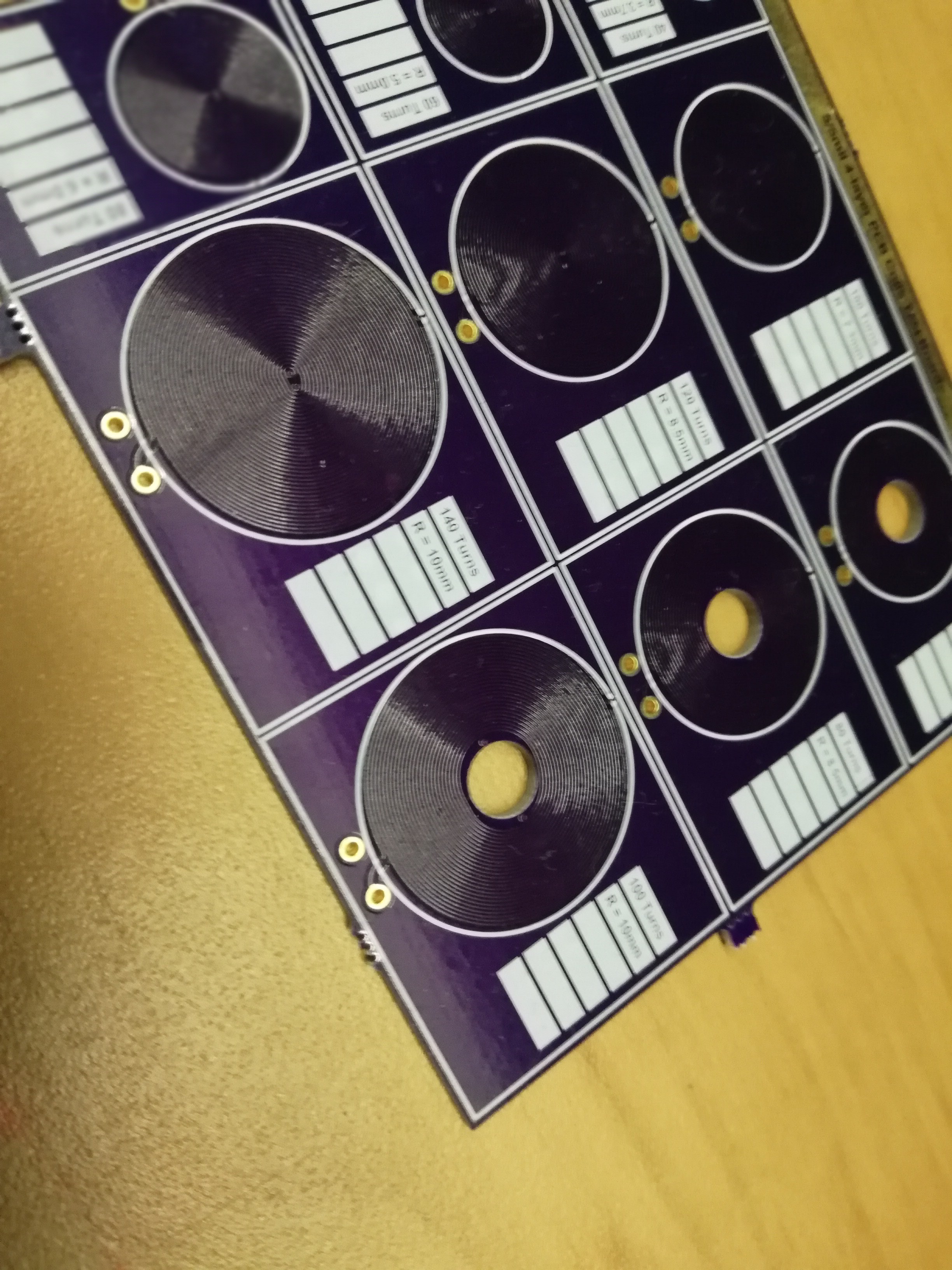
Ok so this is one of the questions i get asked alot. So when starting designing this thing i limited my design to 16mm diamter (because this was this smallest off-the-shelve brushless motor avaible) . To do that eahc coil only had a 5mm diameter area so i had to use the smallest clearances that the manufacturer could support to fit as many turns as possible. Keep in mind that i had two vias in the middle. So I traced around them by drawing a dxf file and then exported each layer drawn into my pcb software
@Frank Buss delta configurations can also be used rather than a start
.oO( have a small metal core sunken into the PCB in the middle... )
to put a piece of metal in the middle the coils need to be substantially larger which increases the overall size of the motor, but i am going to test it out
Nice! EXPERIMENTS!
this is just for testing the coils and their magnetic fields
Project fodder is from @Jarrett : You could draw coils with a hole in the centre, and then use many PCBs stacked up with a tube through them as a coilgun, yeah?
Do the coils extend through all four layers? I mean do you have 4x the apparent coil length/area?
How many layers are those boards (I mean the layers with coils on them)
Once I wrote a library to calculate magnetic fields with CUDA ( http://www.frank-buss.de/magnetfeld/ , the client for which I wrote it, allowed me to release the library as open source), maybe would be useful to simulate different configurations. My library can't emulate a metal core, but I guess there are good programs out there already which can do this, with finite element analysis etc,, so you could even predict the torque before building it.
![]() @Carl Bugeja Have you looked at using/know about planar transformers?
@Carl Bugeja Have you looked at using/know about planar transformers?
@Jarrett Yes you can see the picture above.. not sure about the coilgun though (it was defintly the number one thing requested with my linear pcb motor)
@Kris Winer Their is only one coil which current goes through one layer after the other
@Boian Mitov 4-layers
More layers should improve it right ? ;-)
So in effect, you have 4x the coil area then? You could then try 6- and 8-layer pcbs to increase the field strength...
or you could just stack multiple 4 layer PCBs
yes more layers and thinner pcbs should make it better
![]() I would imagine heat dissipation starts becomeing an issue tho, right?
I would imagine heat dissipation starts becomeing an issue tho, right?
6-layer pcbs are far more expensive though (not ideal for prototype testing)
I think the field strength increases with area and decrease with volume.
@cruz.monrreal my current prototype is going up to 70degrees celsius @ 5v which is not that bad
 yup, 6 layer = crazy expensive ... when you're used to OSH Park ;)
@Carl Bugeja can you tell us about your linear PCB motors and flexible actuators?
2 layers, 0.6 mm thick, are not too expensive, couldn't you just stack like 10 of it?
the thickness will weaken the magnetic field
you want the coils packed as close to the magnet as possible
another option is 2 boards on both sides of the magnet :-D
@Stephen Tranovich so after designing my brushless pcb motor (and getting over the idea that i cannot use it for my drone project) i started looking into coil actuator and thought it would be interesting to make an coil array to actuate some small magnets on it. My first try was the linear pcb motor which was pretty cool. BUT then i decided to try to get the same design but on a flexible pcb. I was not sure if this was going to work because i had to reduce to two layer (because 4 layers flex pcbs are to expensive) so i was afraid that the coils would heat up to much given that the number of turns was reduced by half
But the thinner dielectric had helped in improving the coupling that luckyly enough the flex pcb actuator only goes up to 76 deg celsius @ 5v. So its smaller resistance can be at lower voltages, like a 1 cell lipo
@Boian Mitov I have tried testing two-pcb-one-rotor and one-pcb-two-rotors but it barely had any effect
@Boian Mitov is asking everyone's favorite question: What is the coolest Robot that you have built?
Haha
this was actually my final-year engineering project
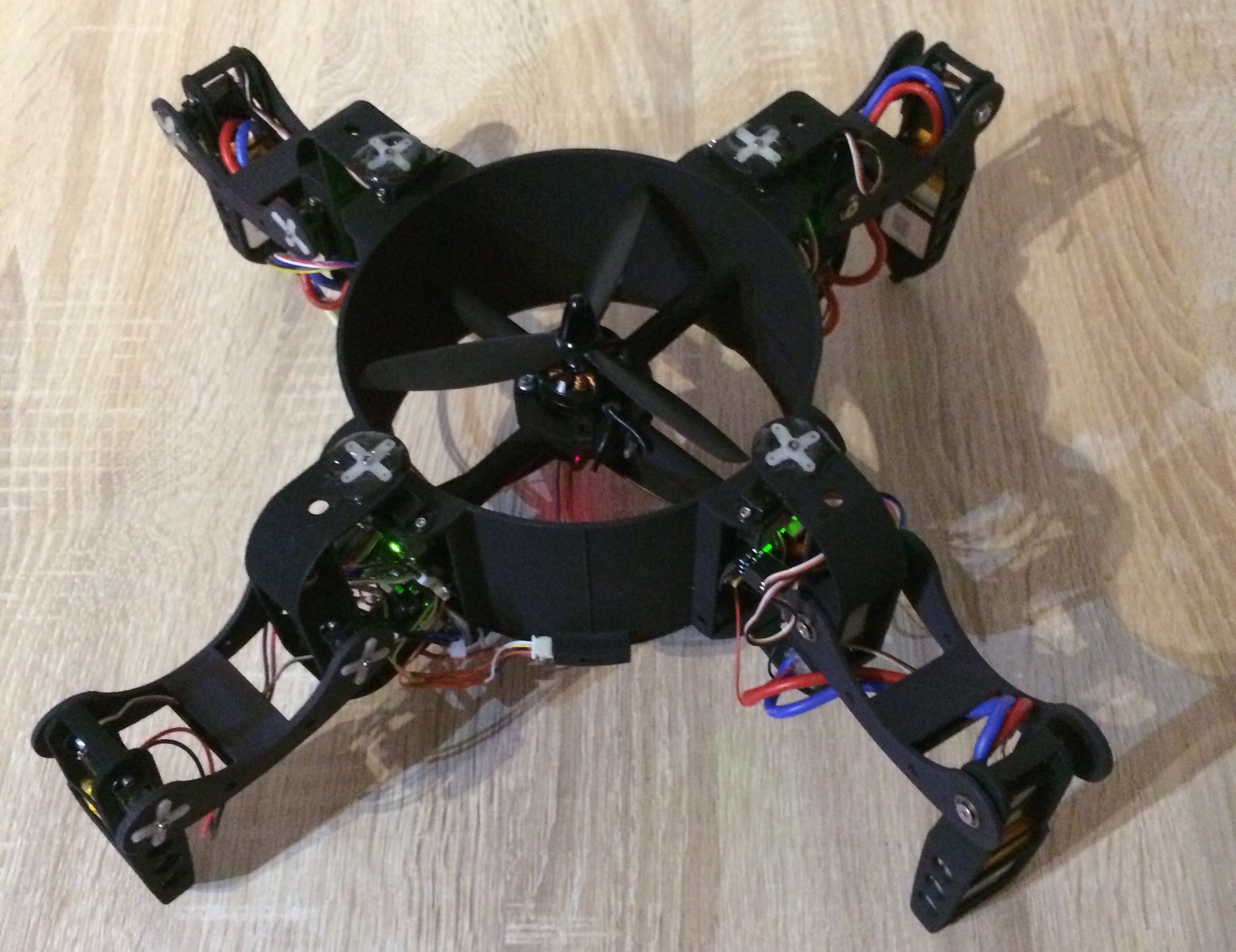
a four-legged hybrid coaxial drone
Wow... Did this thing really fly? Or just for better traction on vertical surfaces?
https://hackaday.io/project/39427-flypod

FlyPod
Back in 2015, I pitched this concept for my final year engineering project. My goal was to design a four-legged robot which can both walk and hover. It has a coaxial ducted rotor in the middle and the rest of its weight is in the legs.
Wow, that's a really cool robot.
It could generate enough trust for hovering. For my project I needed to design the electronics and 3d printed parts to have the first prototype platform. I was planning on continuing this project after my thesis but then ended up shelving the idea because the battery life was too poor. I have tried redesigning it but the battery still is a problem so it not worth investing so much time in the flight controller, as it is very complex to control the robot (also with the legs) in flight - at least that was the concept.
What a fun note to end on!
With that
We've reached the end of this week's Hack Chat
Thanks Carl and Stephen!
A BIG thank you to @Carl Bugeja for coming on and sharing your great projects with us!
Thanks for having me! Its been really fun
Discussions
Become a Hackaday.io Member
Create an account to leave a comment. Already have an account? Log In.