 Victor Joo
Aug. 6th
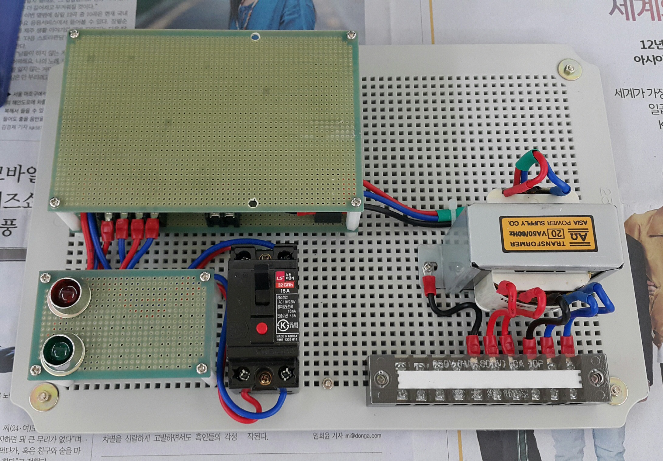
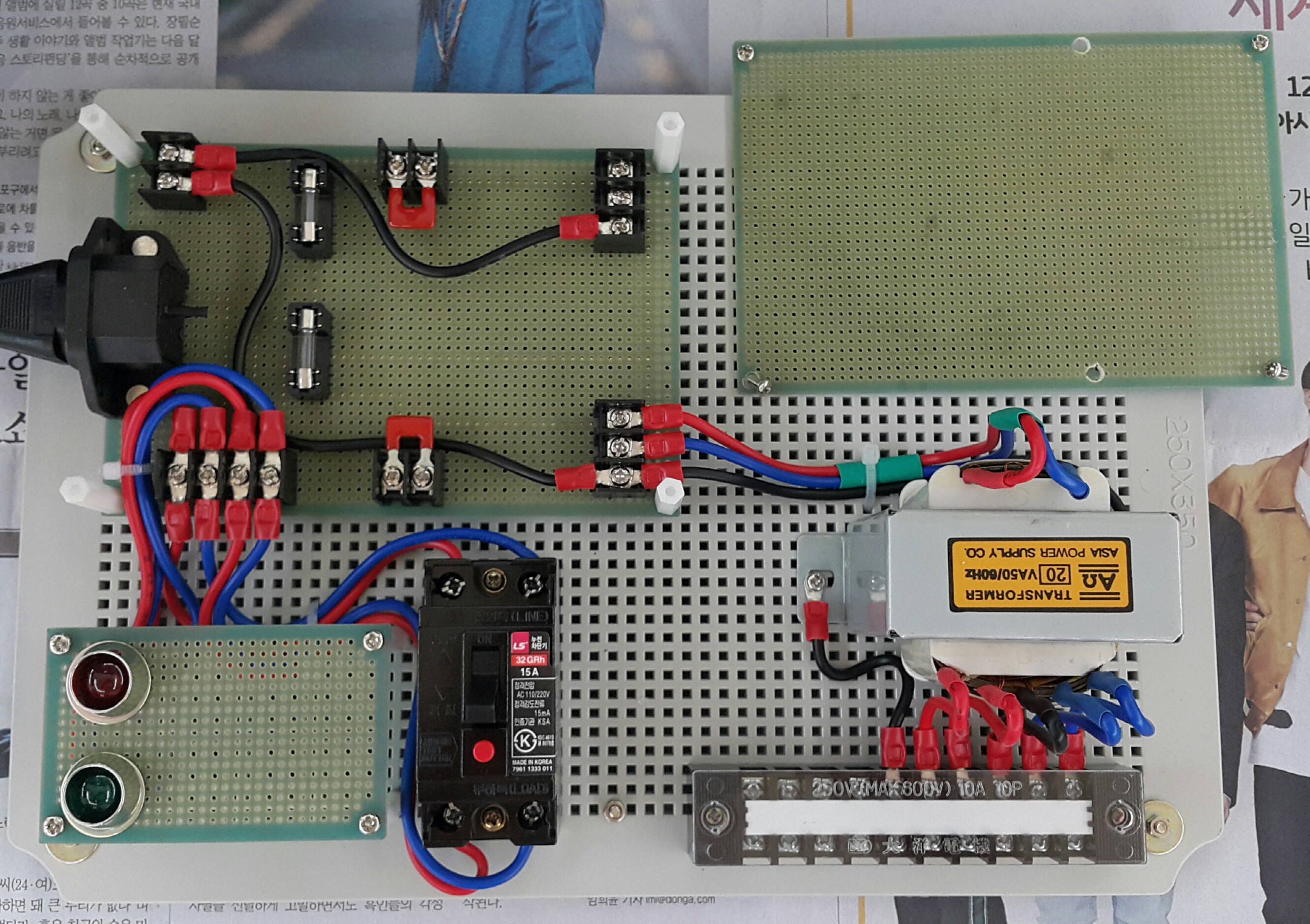
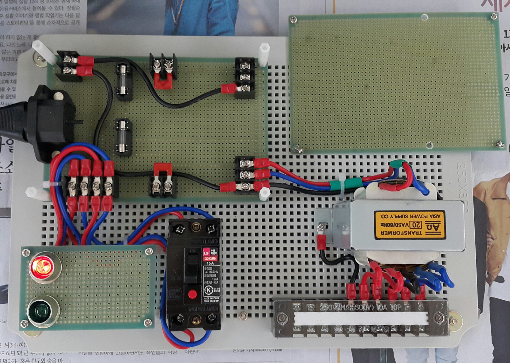
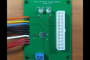
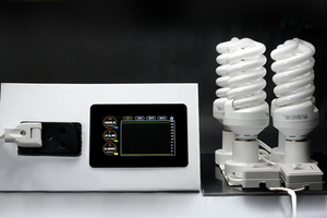
For now, about 40% of the project is completed. What is shown in the picture below is the main connection board and AC mains power input control part.
AC mains power is simply supplied by a 3-pronged AC power cord including ground line.
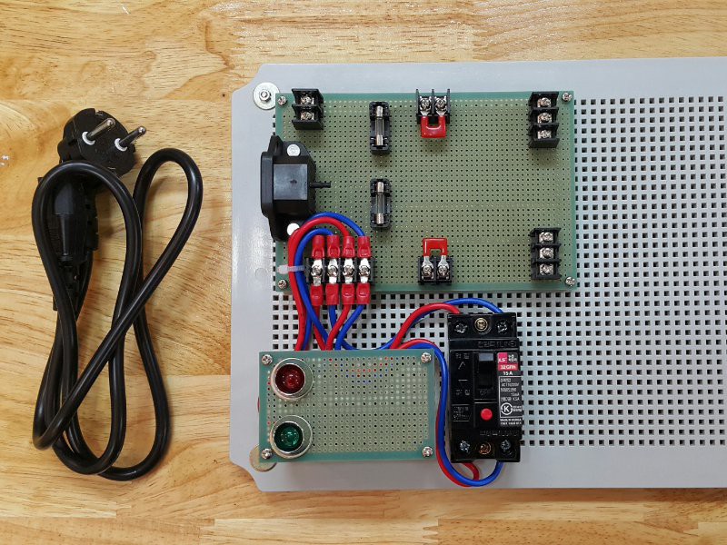
When no AC mains power is applied, none of the pilot lamps turn on. But once the power cord is plugged in, Red light is on as it tells users that AC main power is standby.
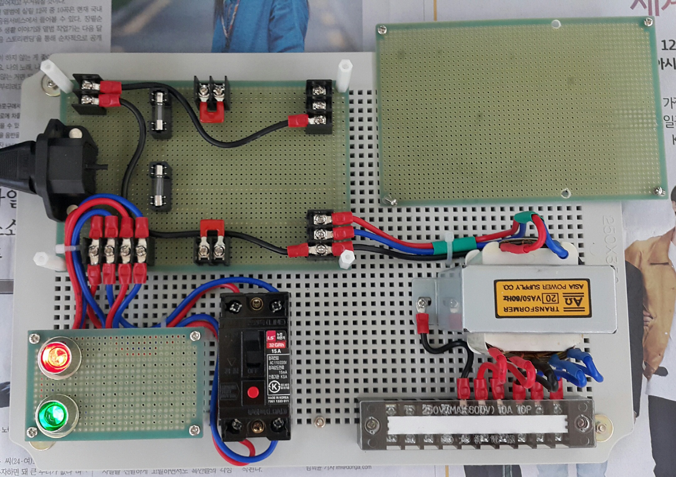
And finally, when the circuit breaker is on, Green light is on as AC power is now applied on the main circuit.
And that's it. That's all I did for the project for now. :-)
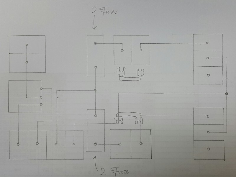
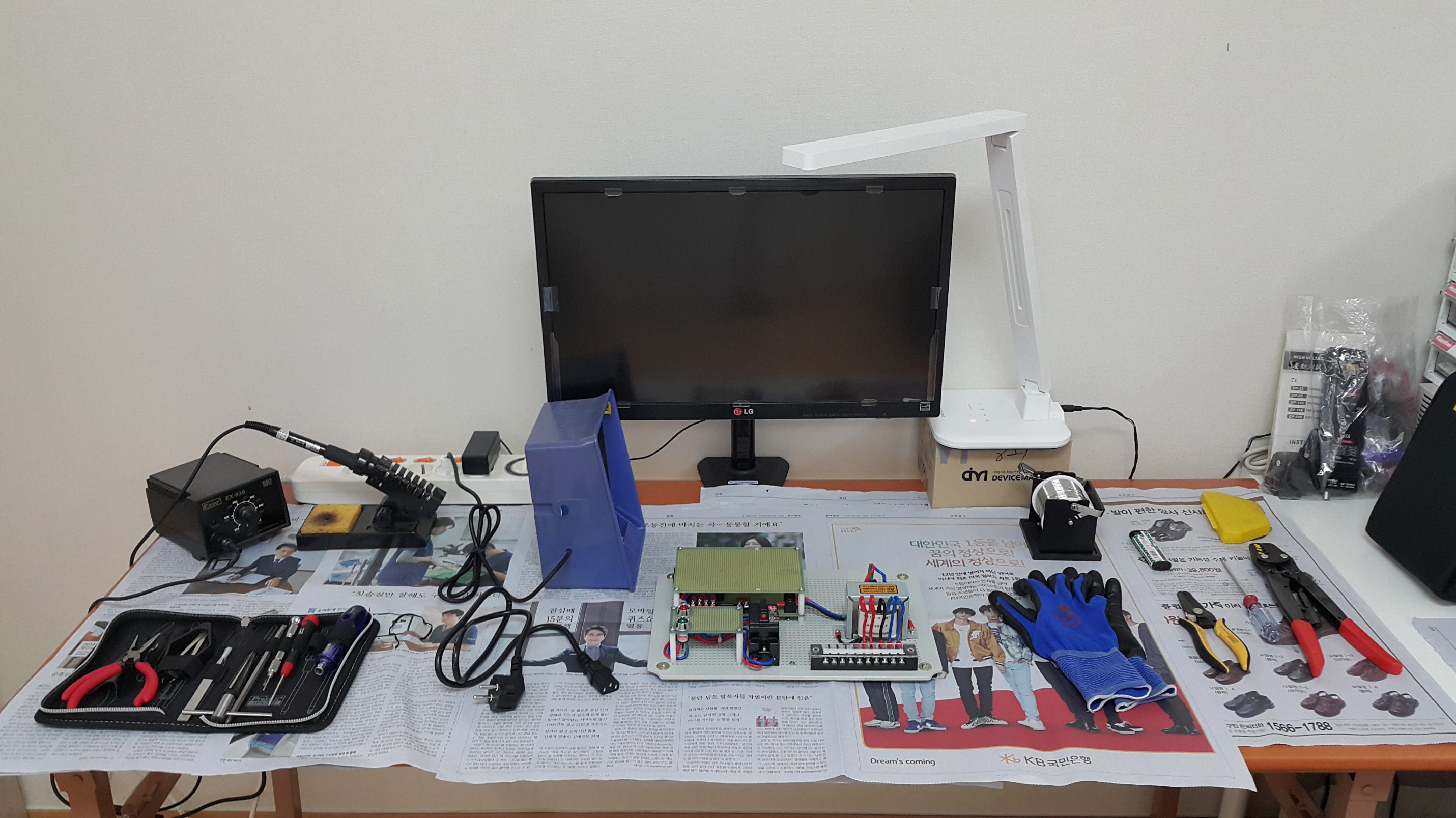
But here's some more, I'd like to tell you how I begin this project from scratches.
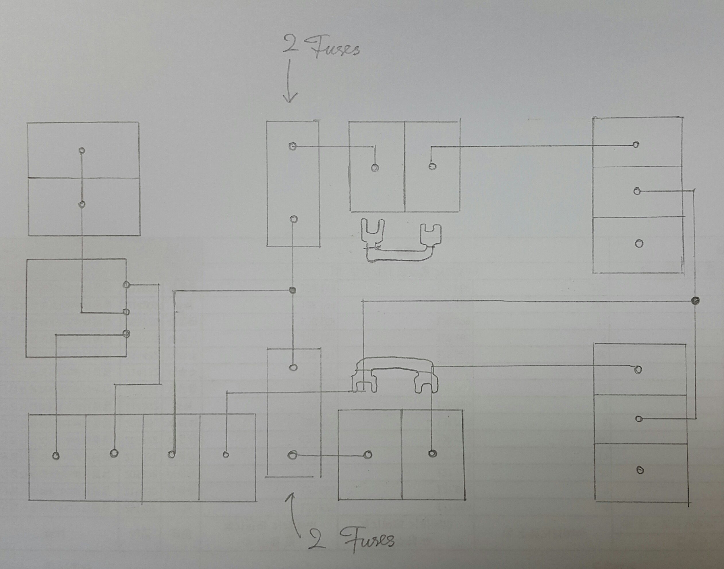
This is my design sketch roughly catched on what I had in my mind. Boxes drawn are representing terminal tables and lines drawn are circuits connecting between them.
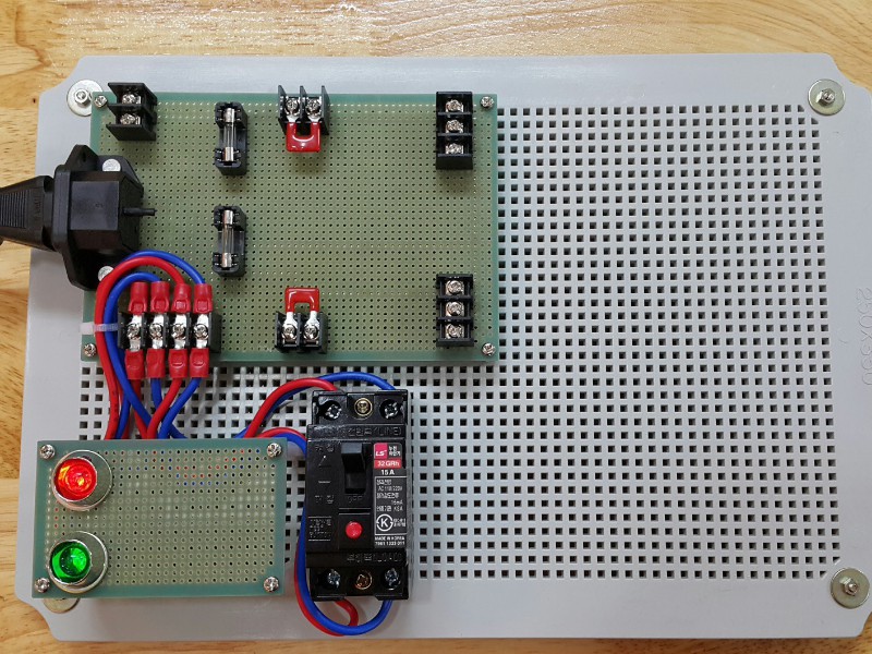
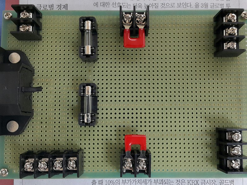
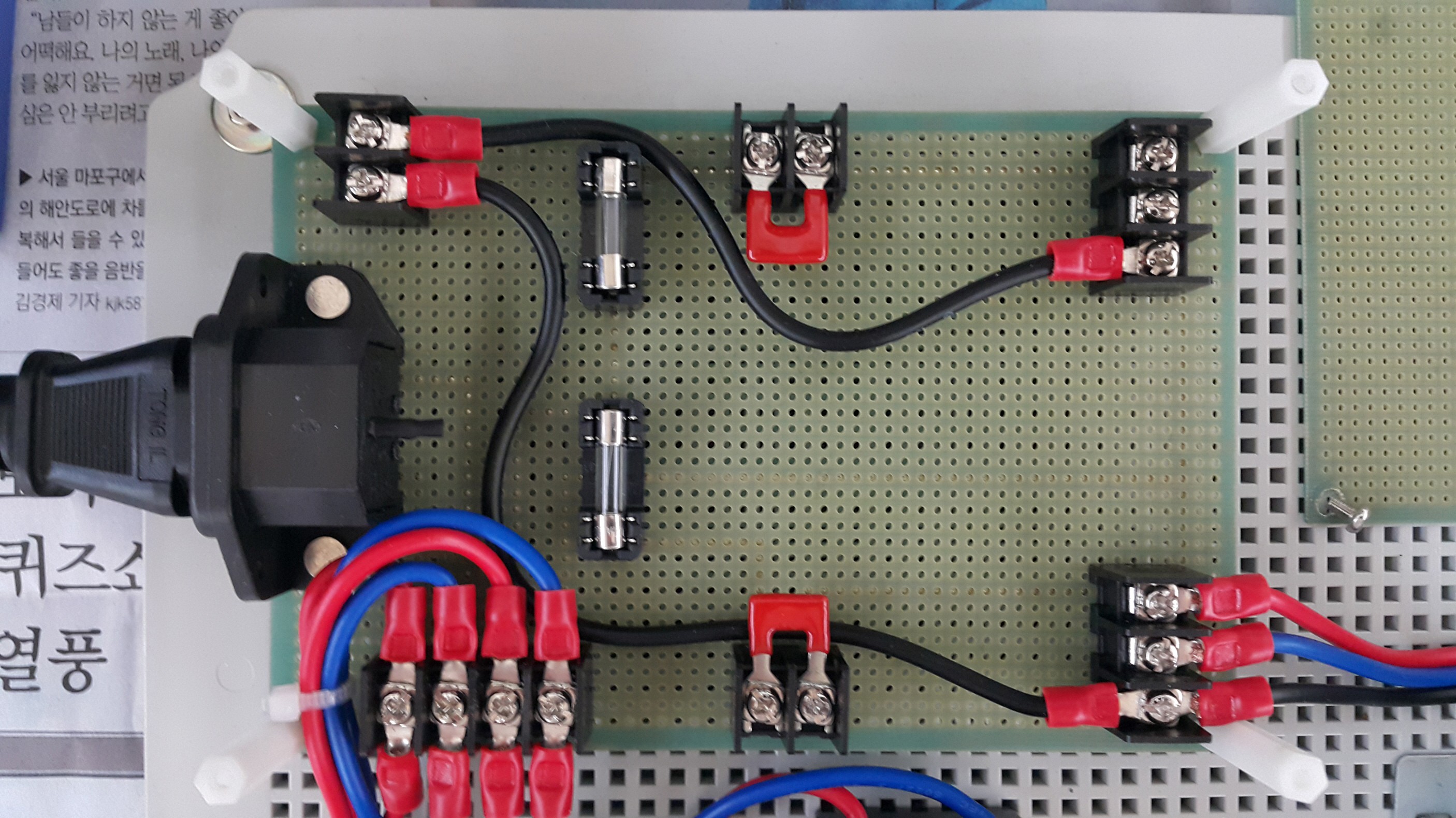
A close look at the main connection board. AC power socket, Terminals, Fuses in holders, and shortbars can be seen here.
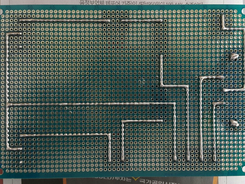
Bottom side of the main connection board. I used tin plated wires to connect leads when soldering.
To make sure for the safety, I used an empty prototype board to cover the main connection board.
And also, I'm going to determine the best position to mount the transformer near the terminal table. And that's for the tomorrow.
Thank you for reading and keep watching me going on the project.
Have a nice day!
Aug. 10th
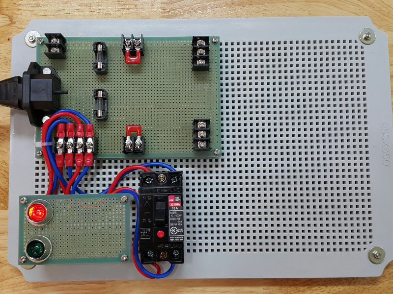
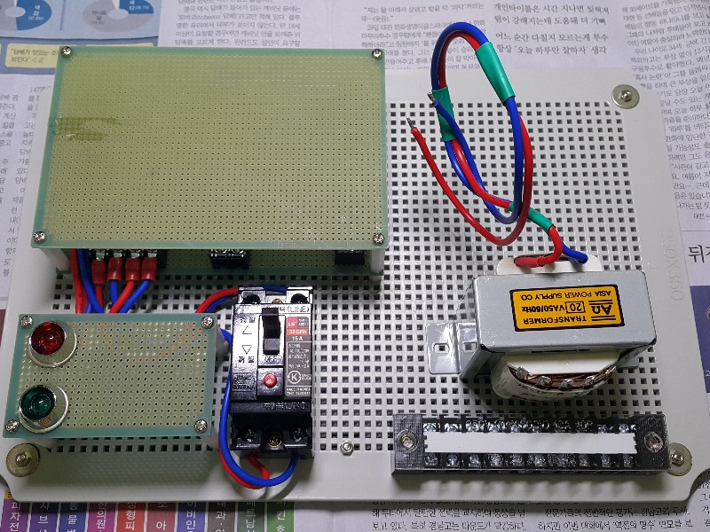
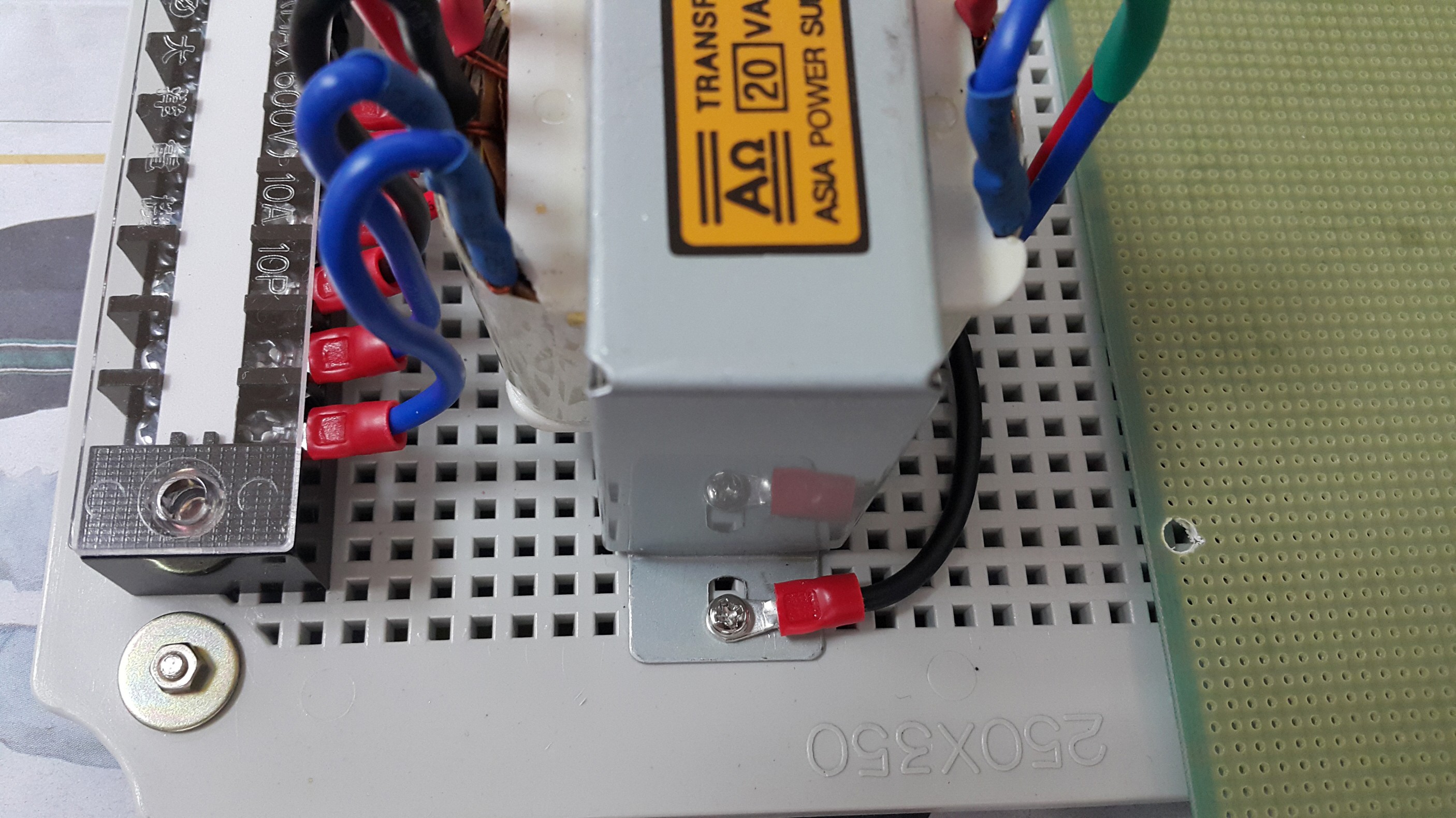
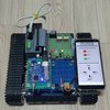
This is what it looks like when I mounted the transformer near the main connection board with the safety cover on .
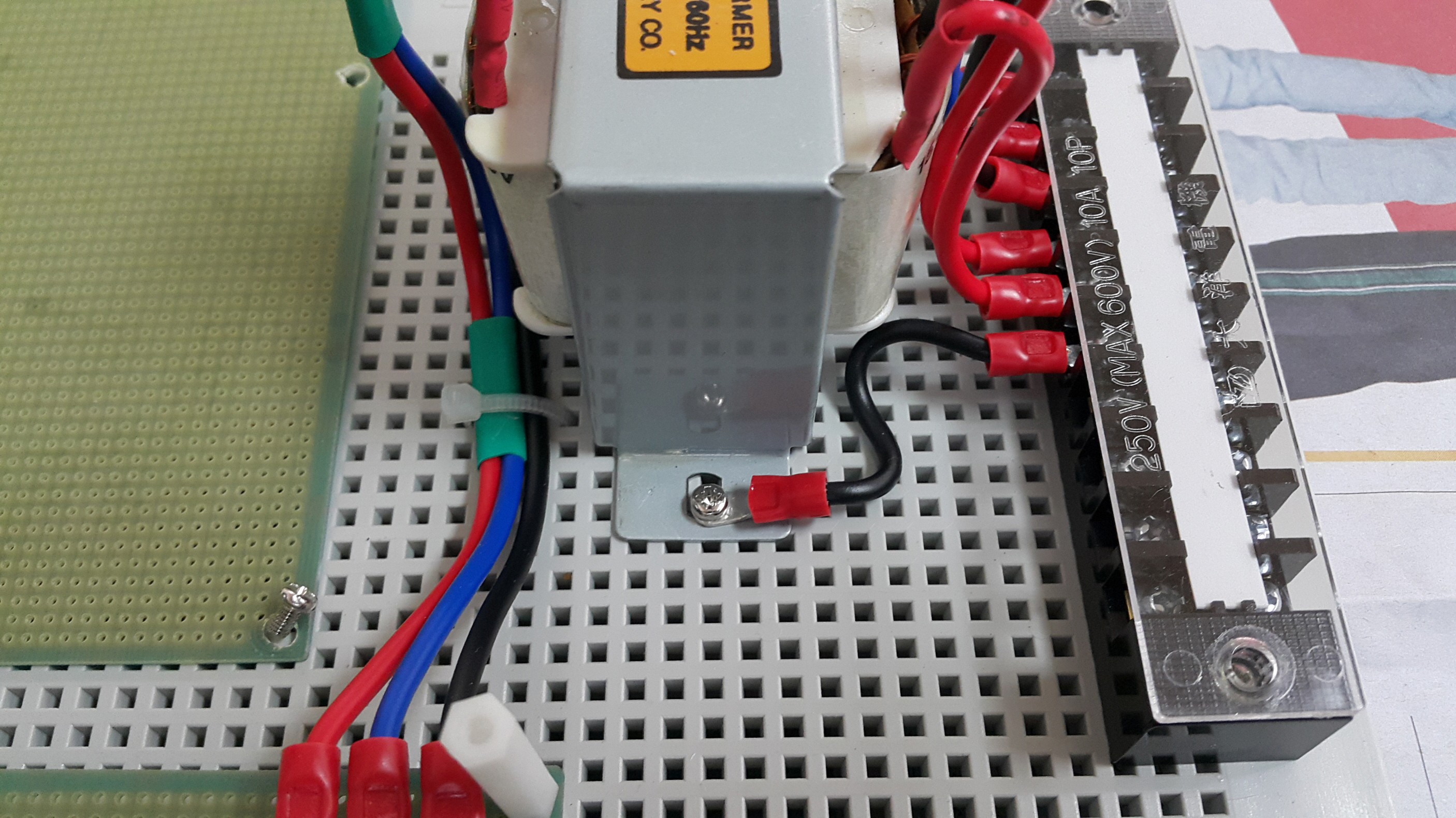
Terminal block is also mounted to hold output wires firmly on output terminals.
OK, let me show you what I've done under the safety cover. I've also wired the ground networks which is connected to AC mains for the safety.
This ground line is connected to the transformer chassis and the ground terminal of the terminal block.
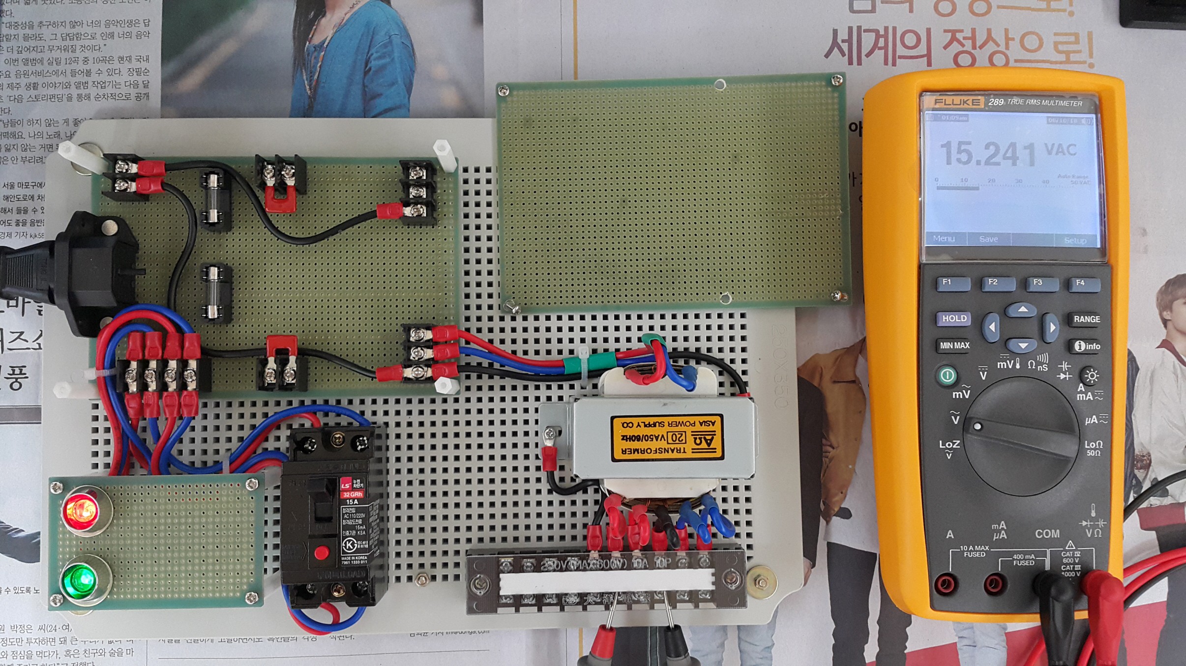
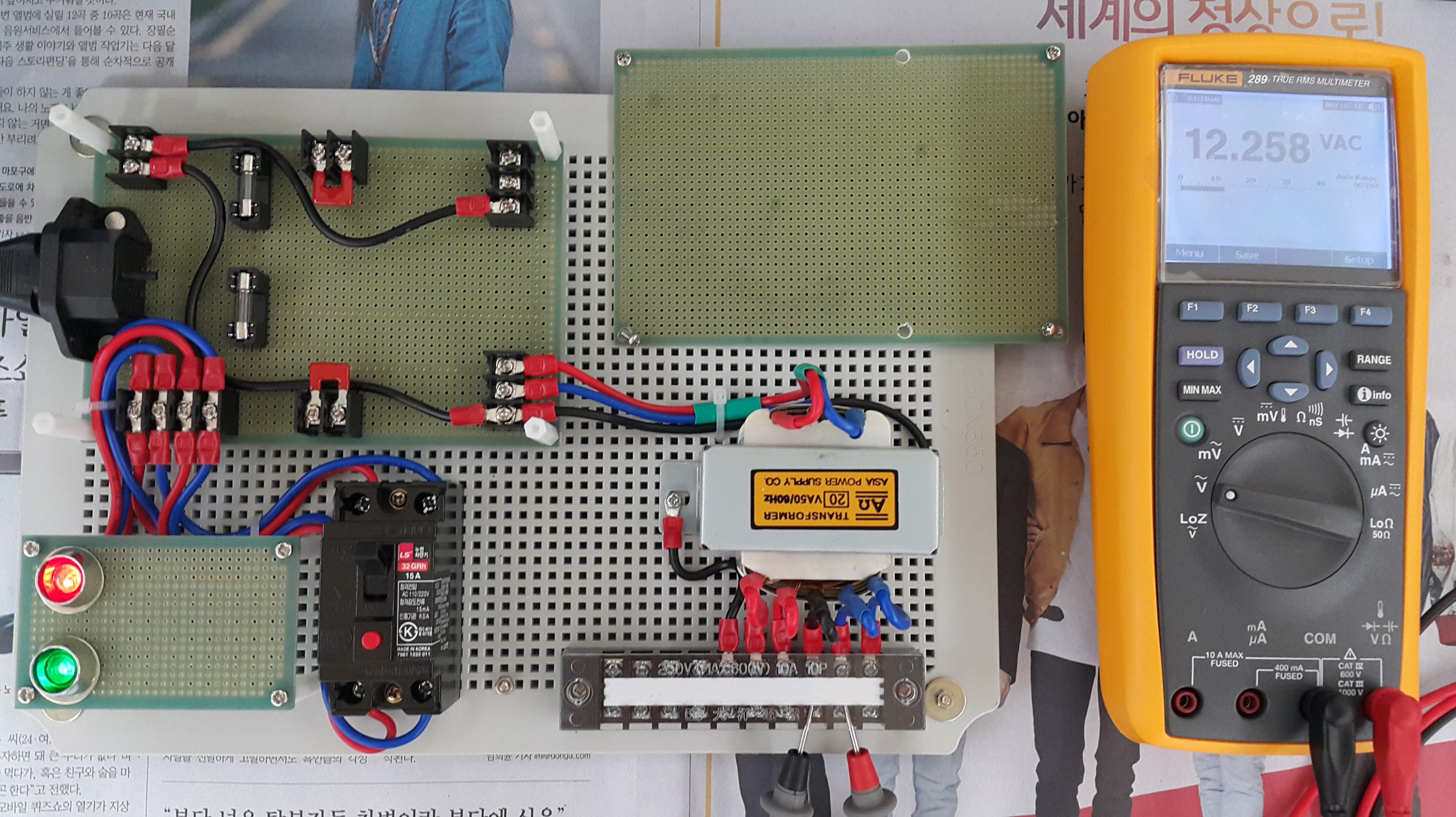
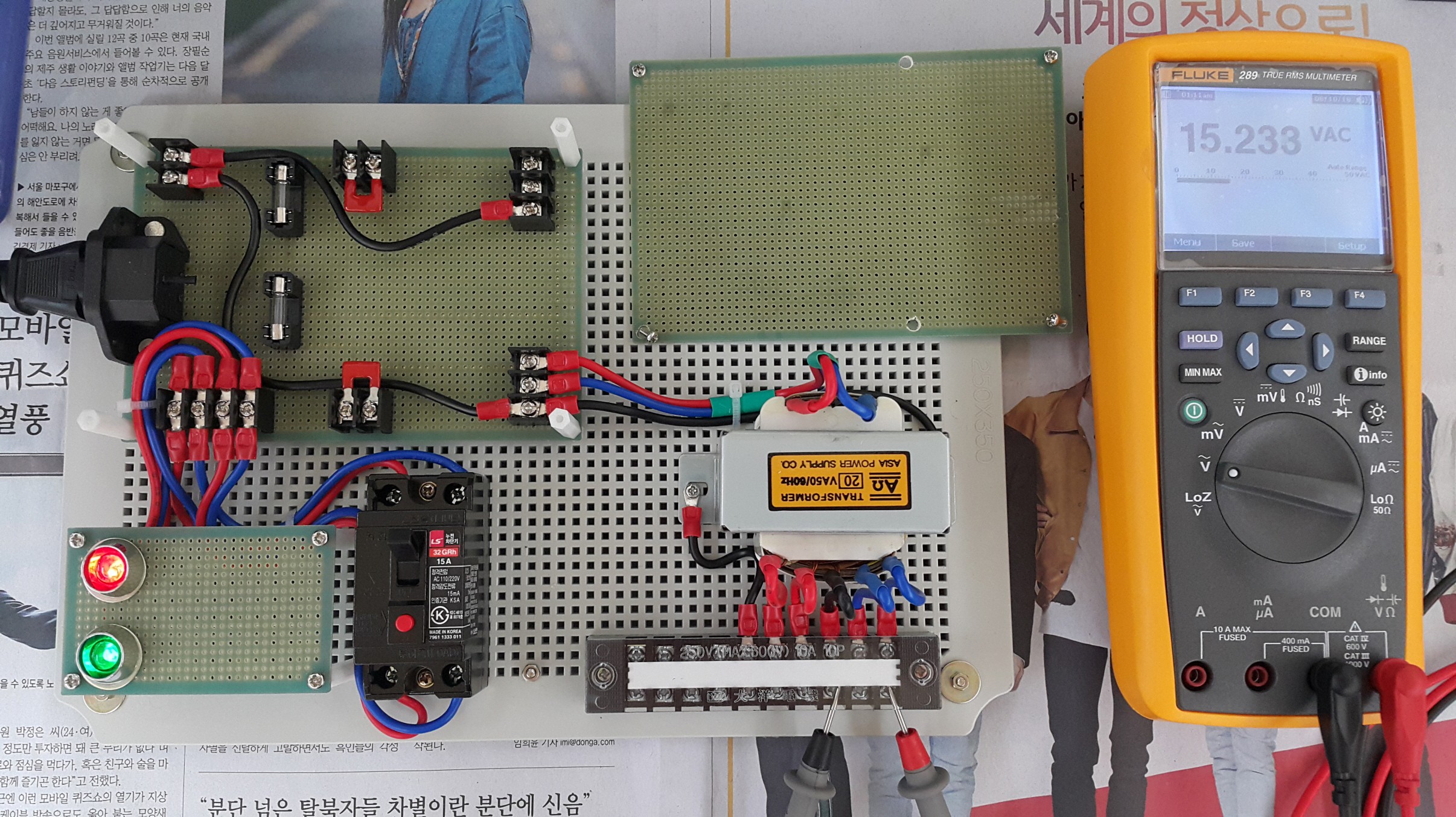
Now, powering up the system for some voltage measurements.
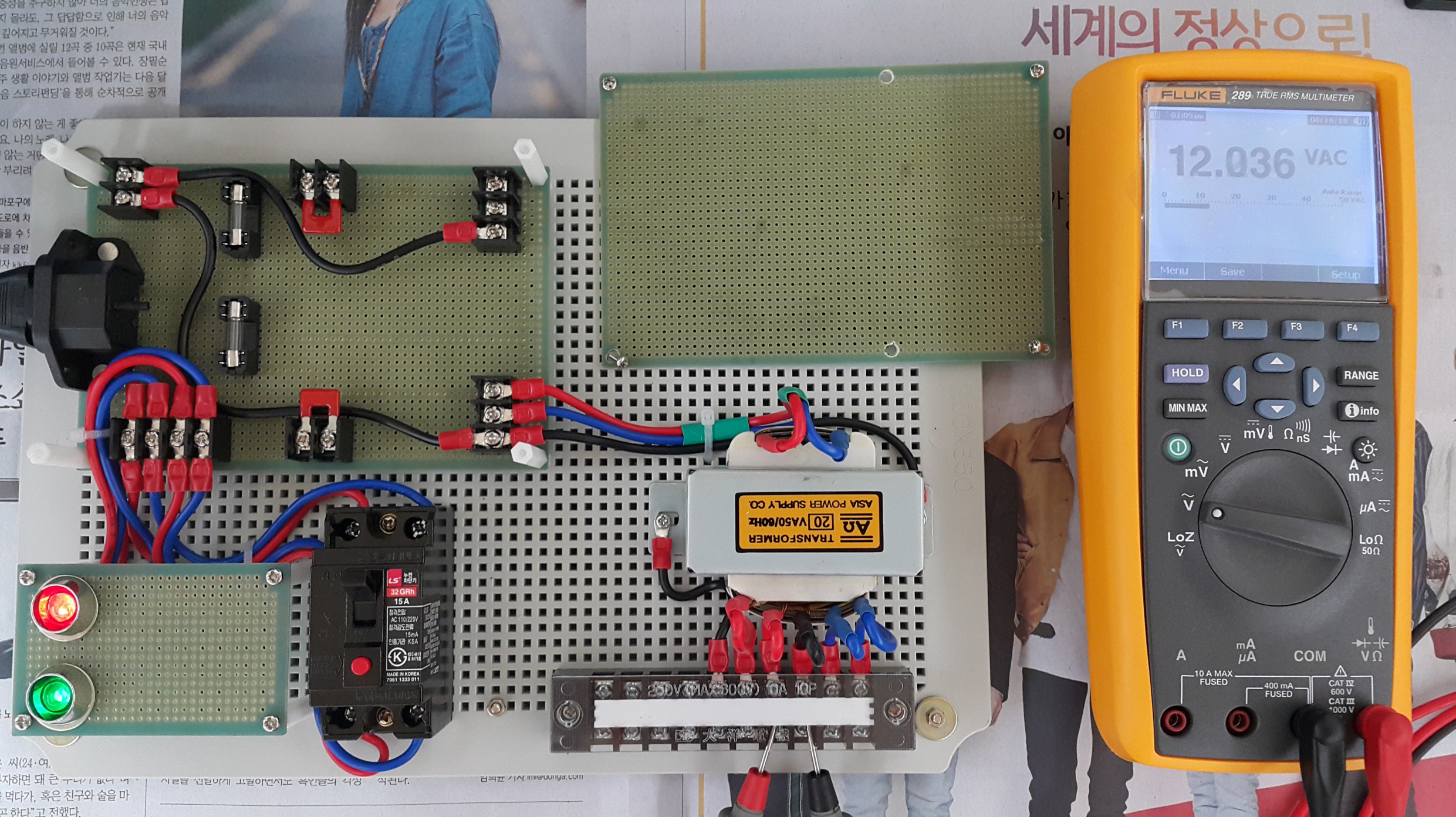
Measuring output voltages of low voltage AC power supply part. The output transformer has 5 voltage output terminals: 15V - 12V - 0V - 12V - 15
Voltage reading was quite satisfying, all the outputs were showing almost correct voltages with no loads on.
And that's all for today. Thank you for reading and keep watching me going on the project.
I'll come up with the next progress.
Have a nice day!
 Dave's Dev Lab
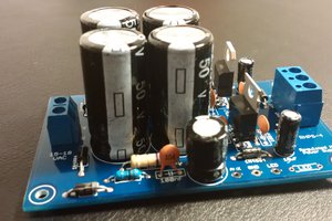
 4D Makers
 Ryan Karl
This might be the cleanest proto-board wiring job i have ever seen.