Got it up and running! After a good day's work fixing my soldering, writing some test software, debugging, scoping, etc. I have a working circuit board and very basic firmware.
And...it looks like this now:
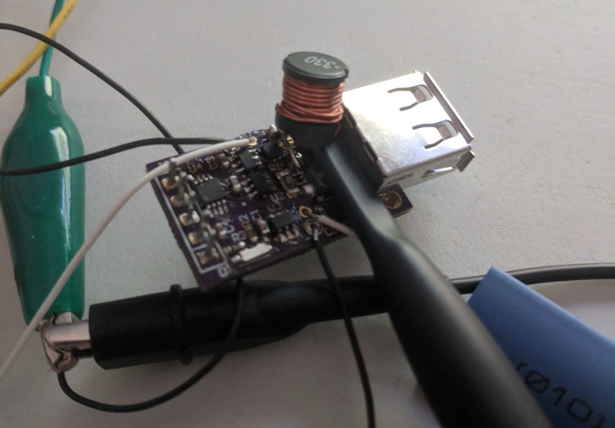
So... the inductor. Obviously this isn't what I had in mind. I guess I was too excited to get a board ordered to actually calculate the inductance I needed in the buck converter. My original was a 1 uH inductor. This is what was called out for the boost module, so I figured the buck had similar needs and could use the same inductor.
Which is obviously wrong. The boost module has a switching frequency in the megahertz, where the highest I can get the microcontroller to do is 320 kHz (160 kHz if I need 100 steps of PWM).
So I scrounged and found the big through-hole inductor shown, and got that to work.
In other news, turns out I misinterpreted the rules for the one-square-inch challenge (or they changed the rules all the sudden?). They want the entire board to fit, including the components. This doesn't fare well for my big USB-A connector hanging off the edge of the board.
The USB connector needs to be there; it'd be stupid to not have it, given the board's intent is to be a USB charger. I could move it off the board, but that's not a clean solution. I have enough flying leads already.
So how to fit the connector within my square inch? My first thought was a vertical connector, but that makes the positioning awkward. So I think the solution is to switch to a surface-mount connector and put it on the back of the board. This makes the board thicker, but I think it'll work if I keep all the big parts on the bottom.
I'm a little upset that I have to redo much of the layout to make this work, but I guess they call it a "challenge" for a reason. And I have to redo a good chunk of it to fix my footprints and get a bigger inductor on there. Maybe I'll even have space for some more input capacitance.
Anyway, I should have enough time for a respin. Next step is finishing up the firmware, doing some testing, then I can respin and get a nice final product.
And speaking of firmware:
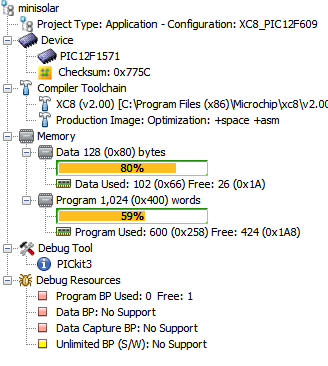
80% data memory usage already? (tugs collar nervously) I can safely say I've never pushed a microcontroller this close to its limits.
Discussions
Become a Hackaday.io Member
Create an account to leave a comment. Already have an account? Log In.