If you don't feel like reading this: 90% efficiency, with some unfortunately large error bars.
I finished putting together the Rev 2 prototype, tweaked the firmware a little, and it works! Both the input and output converters are doing their job, power points are tracked, the LED does exactly what I want it to.
I wanted to put together the whole thing and mark the project as complete, but there's one more thing I need to test:
Was all of this worth it?
I added a buck converter with MPPT to this circuit on the belief that I would get more energy from that than simply connecting the solar panel to the battery. And while I picked out efficient parts, I didn't have a good way of estimating the efficiency of the build before putting it together.
Therefore, today's lesson: How to measure efficiency.
Recipe for Power Efficiency Measurement
Ingredients:
- A 4-channel oscilloscope
- 2 Precision low-value resistors
- An appropriate power supply
- An appropriate load
- A converter to test
Step 1: Preparing the ingrediants
- A 4-channel oscilloscope
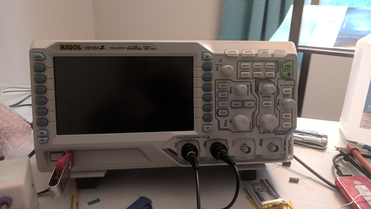
Rigol. No surprises there. First time I've gotten to use all four channels though.
- 2 Precision low-value resistors
I dug around my parts bin and found these bad boys:
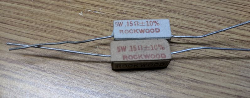
Oops, did you say precision? I thought you said +/- 10%.
We can fix this. Power supply + DMM + Scope = Precision resistance measurement.
Input current resistor: 5.06 Amps of current generates 0.988 V -> 0.195 Ohm. Well outside even the loose tolerance specified. I double-check all my connections; either my instruments are way off or this resistor is. I'd like to trust my instruments, while these resistors are many decades old. I'll take the measurement as fact.
Output current resistor: 5.06 Amps generates 0.946 V -> 0.187 Ohm.
- An appropriate power supply
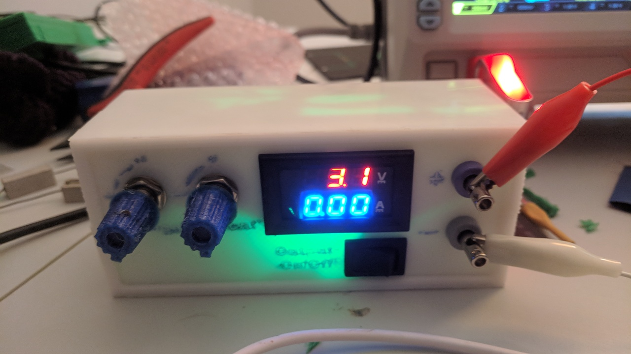
Home made! And crappy! But it does the job, even if I can't really control the current and the current measurement is off by nearly a factor of 2. I built it based on this: https://www.thingiverse.com/thing:2085223
Since my converter expects a solar panel as an input, I add a 33 ohm series resistor out of the power supply. That way, it has a well-defined maximum power point at 1/2 the source voltage.
- An appropriate load
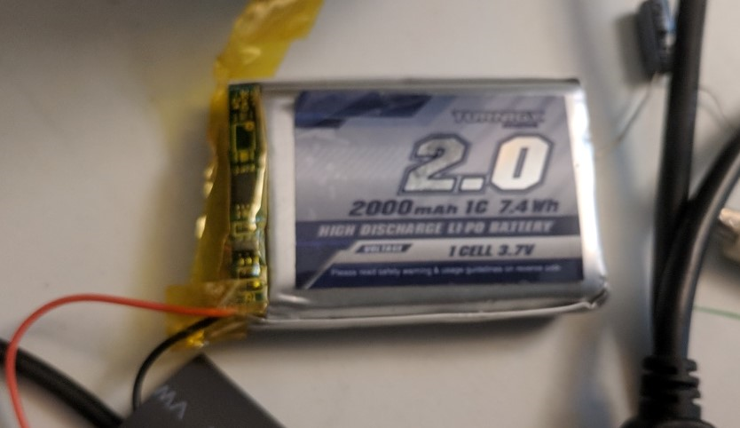
My converter expects to charge a battery, so this little lithium cell is my load. It's different from what I intend to use in the final device, but it has some on-board protection, which will be good when I accidentally short this thing out.
- A converter to test
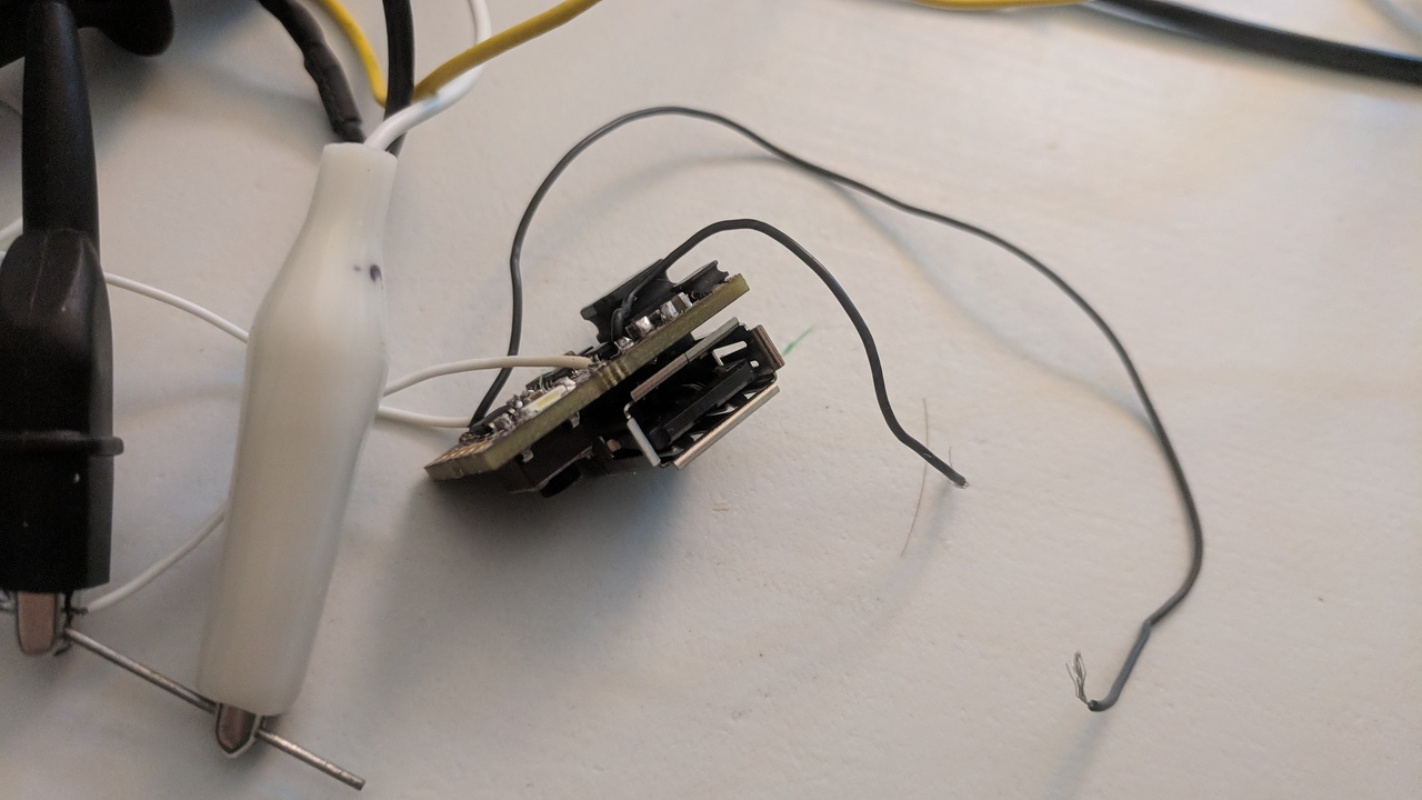
Right here on my desk. Did I mention it's small?
Step 2: Setup
In order to measure efficiency, we need to measure the input power and output power, as your standard efficiency formula shows:
To get electrical power, we need voltage and current, according to P = V * I. So our formula is:
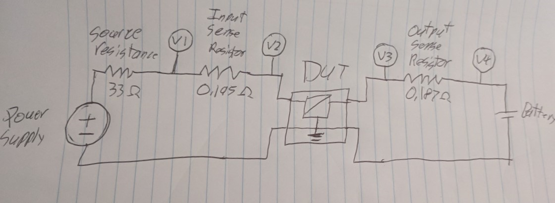
Problem with this is that I can't measure current with my oscilloscope. I can with the DMM, but I only have one of those. This is where the "precision" resistors come in. By measuring voltage on each side of a known-value resistor, I can calculate the current running through it. Therefore, I want to set up my circuit like this:
Note from the future: This won't work; don't do this. I'll find that out later.
By substituting my voltages and currents with the values I measure and calculate, I arrive at the following:
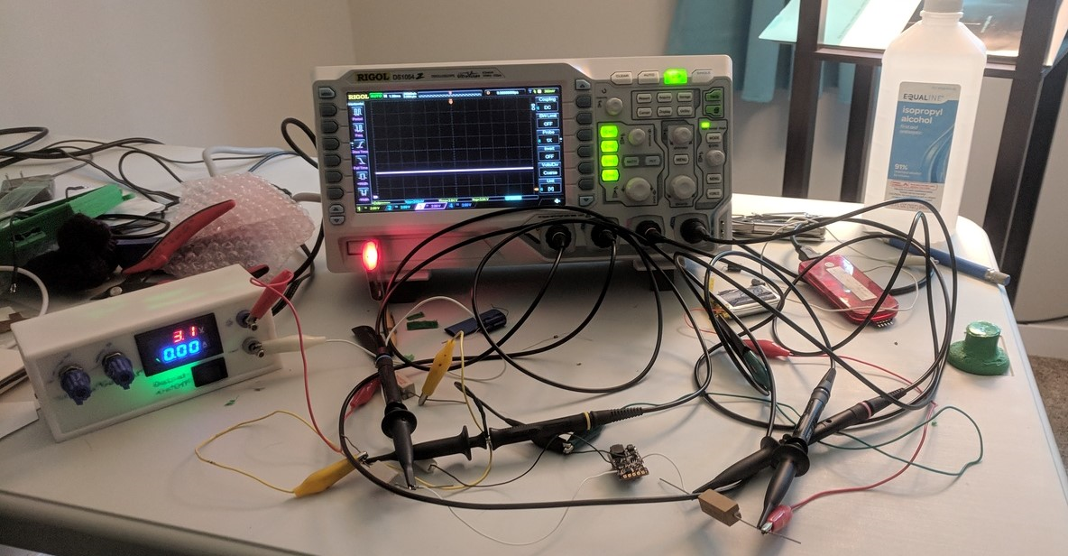
It's not the prettiest thing wired up:
Step 3: Run (away)
For this test I'm going to use my standard code. Battery level is 3.8 Volts, switching frequency 40 kHz. I'll shoot for about 100 mA input current. We'll fire up the power supply, wait for things to level out, and take a capture of the data. The math functions on this scope aren't sufficient to carry out the formula above, so I'll import the raw data to MATLAB.
I take the data onto a USB drive, load it up in MATLAB, and do a little this:
>> mean((CH3 .* (CH3-CH4)/0.187)./(CH2 .* (CH1-CH2)/0.195))

ans =

    0.1336
...What? I know for a fact this is more than 13% efficient.
I tried again, this time ground every individual scope probe, and tweaking my function to average each value before inserting them into the equation...
>> (mean(CH3) * (mean(CH3)-mean(CH4))/.187/(mean(CH2) * (mean(CH1)-mean(CH2))/.195))

ans =

    1.1277
Well, that's... better?
Step 4: Hang head in shame
I was so antsy to do this test, I forgot something: Oscilloscopes aren't super precise with DC values. So my method of measuring current is flawed; I can't get a reasonably precise reading by subtracting two probes. Let's try again:
Another note from the future: this only works if your power supply has an isolated output. Oops.
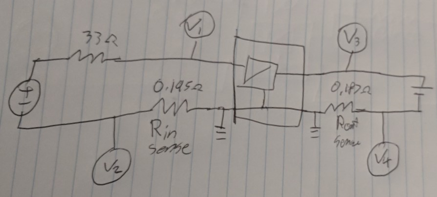
This time, I measure each current with a single probe, and I can turn up the gain to measure much more accurately.
So I tried that, and discovered that my power supply isn't isolated, which means current could bypass the input sense resistor through ground. So this scheme isn't any good either.
So I'm going to have to do this the old fashion way: Probe voltage 1, probe voltage 2, break circuit and probe current 1, same with current 2. Write them all down, pull out the calculator.
Here it goes...
Vin: 4.62 V
Vout: 3.92 V
Iin: 165 mA
Iout: 170 mA
That gives me 3.92*170 / (4.62*165) = 0.87
If that's right, my circuit's efficiency is about 87%. I'm sure there's a great deal of error bars in there, and maybe I'll have to come back to this experiment. My main concern is that my circuit isn't operating exactly the same during all 4 measurements. But for now, I have a number, and it's in the range I expected.
But that brings back the question: is it worth it? This experiment shows my output current only slightly higher than the input current, so it's a very slight gain. However, the input voltage is pretty low; my solar cell's MPPT voltage should be closer to 6 volts. What if I increase my supply's voltage?
Vin: 5.20
Vout: 3.95
Iin: 166
Iout: 200
3.95*200/(5.2*166) = 92%
Not bad, and a pretty big boost. A linear converter in this instance would only get me 3.95/5.2 V = 76% efficiency.
One could extrapolate from this. Imagine my solar panel at its average of 6 V, and battery cell at its average of 3.6 V. A linear converter would get me 60%, where mine seems to average around 90%. That's 50% more power I'm getting out of the solar panel!
Step 5: Act all confident
So yeah, I think that answers my question. My tiny boost converter is getting me a good deal more power out of my solar panel, optimistically 50% more power. And if anyone asks, I totally measured that exactly on my first try and didn't have any issues at all!
At least, now when I see 4 high-precision DMMs stacked up, I'll understand they needed that many.
Discussions
Become a Hackaday.io Member
Create an account to leave a comment. Already have an account? Log In.