 Audrey Robinel
In order to be able to make tracks, i must be able to avoid slipping. Iv the track slips on the wheel, then i'ts wasted power. In order to solve that, i decided to add cogs to the wheels. Then it got me thinking : what about using the same system as gearings?
So let's see how our wheels and cogs are made.
First of all, we define the central hub, with a hole for the central axle, and holes for a user definable number of screws hole around it. Each can be countersunk or not.
When we have the central hub, we decide the number of arms connecting the central hub to the exterior part of the wheel. The lenght of the arm is not set, but calculated : we set the user definable overall wheel radius, the rim thickness, and thus other variables are calculated.
However, you don't get to set the radius directly, but rather the number of cogs wanted on the wheel. Thus, the radius is calculated as a function of cogs sizes.
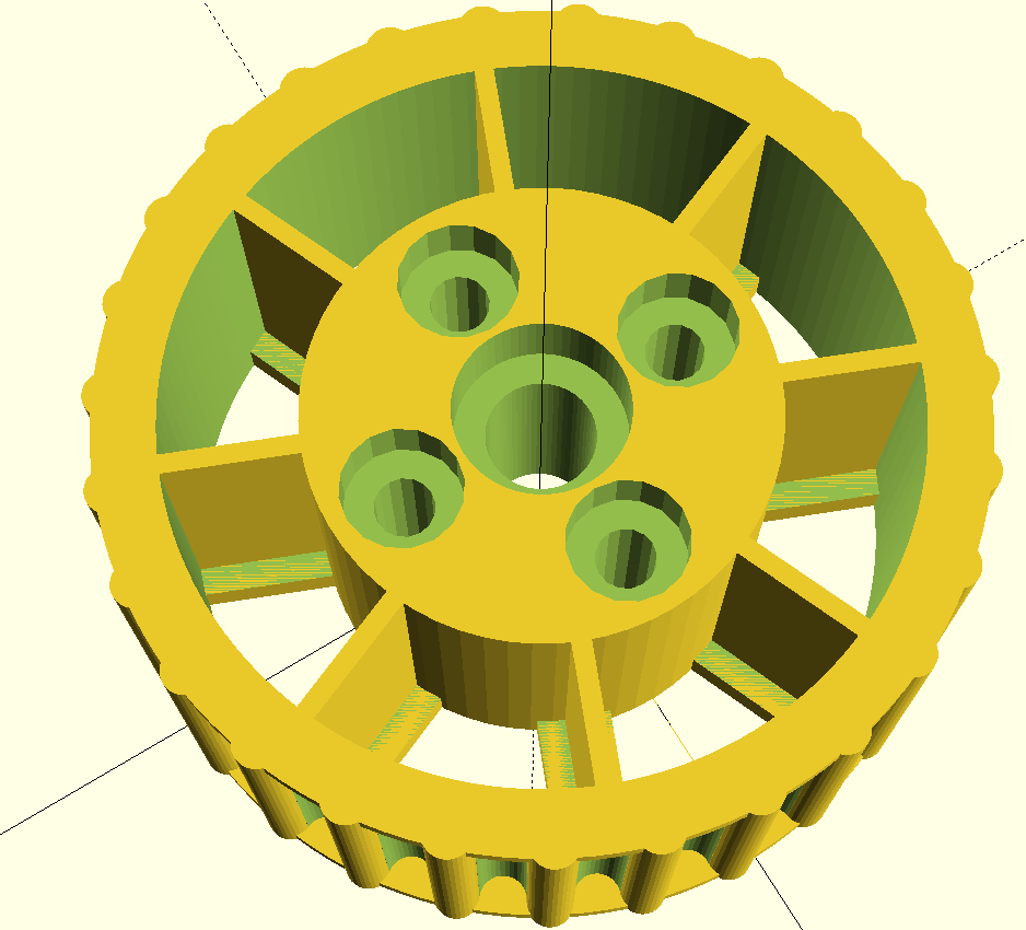
On the render above, you can see a wheel with the lip, 8 arms, counterunk holes, and 27 cogs (thus causing the wheel to be slightly over 20mm radius).
The exact radius of the wheel is printed in the openscad output box.
This makes it so that unless you change the cogs size, all wheels are compatible and can be used as cogs. On normal wheels, a lip is generally added. Not thick, but just to keep the track or tyre from slipping on the sides. On a cog, you simply set the lip thickness to 0.
Now, we can use a cog to turn the previous wheel. However, when a track or a tyre is installed, the cogs are not accessible anymore. The solution here is to use a cog secured at the back of the wheel, using a chosen amount of screws, and a second cog secured to the motor axle.
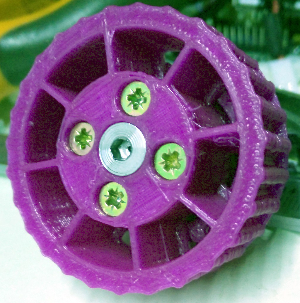
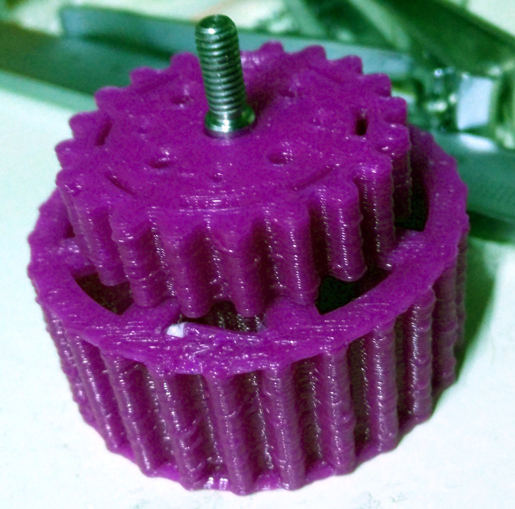 On the picture above, you can see a 22 cogs gearing on a 27 cogs wheel, using the same axle. On the picture below, you can see how it is secured with 4 screws. Note that all screws are countersunk, and thus the side of the wheel has nothing sticking out to block the robot on an obstacle.
For this assembly, i simply used the same hub for both the wheel and the cog, but different thicknesses.
The next step is to print another cog of the same size for a 1:1 ratio, but whose hub will match the motor fixation. For my first tests i'll simply use a continuous rotation servo, so my motor gearing matches the horn holes pattern.
Then in order to have the gearing functional, we have to have the motor axle properly placed so that both gearing interlocks well. This is also taken care of by the library, but we'll come back to this in a later post.
In the next post, we'll stay focused on the wheels for now and talk about the tyres that goes along with it.
Discussions
Become a Hackaday.io Member
Create an account to leave a comment. Already have an account? Log In.