 greg
gregThe goal of this project is to bring FPGA development one step closer to Adafruit easy.
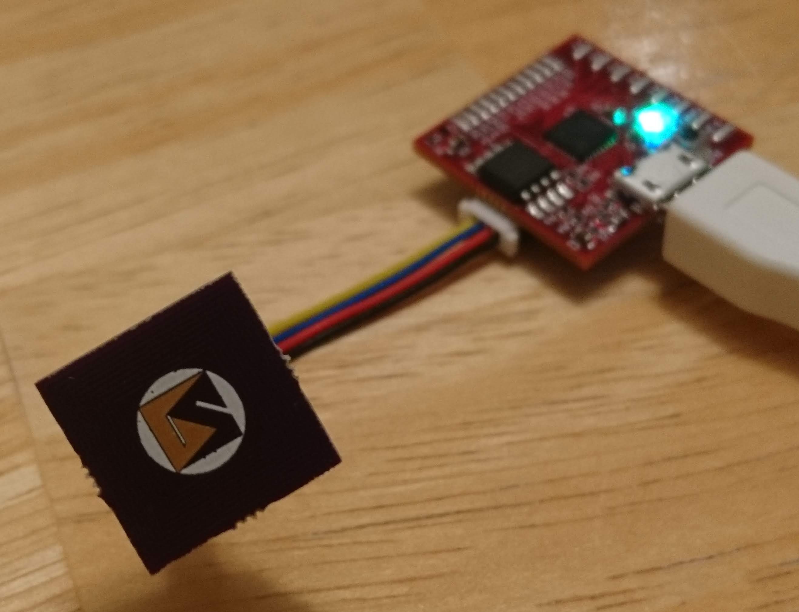
This project is a combination of open source hardware and software that provide features commonly needed in FPGA designs, primarily: programming interface, USB communication, and analog signals. This project is being designed to run on any operating system and being an open source project, the features of this project can be expanded over time to add additional utilities and support for more targets.
Targets:
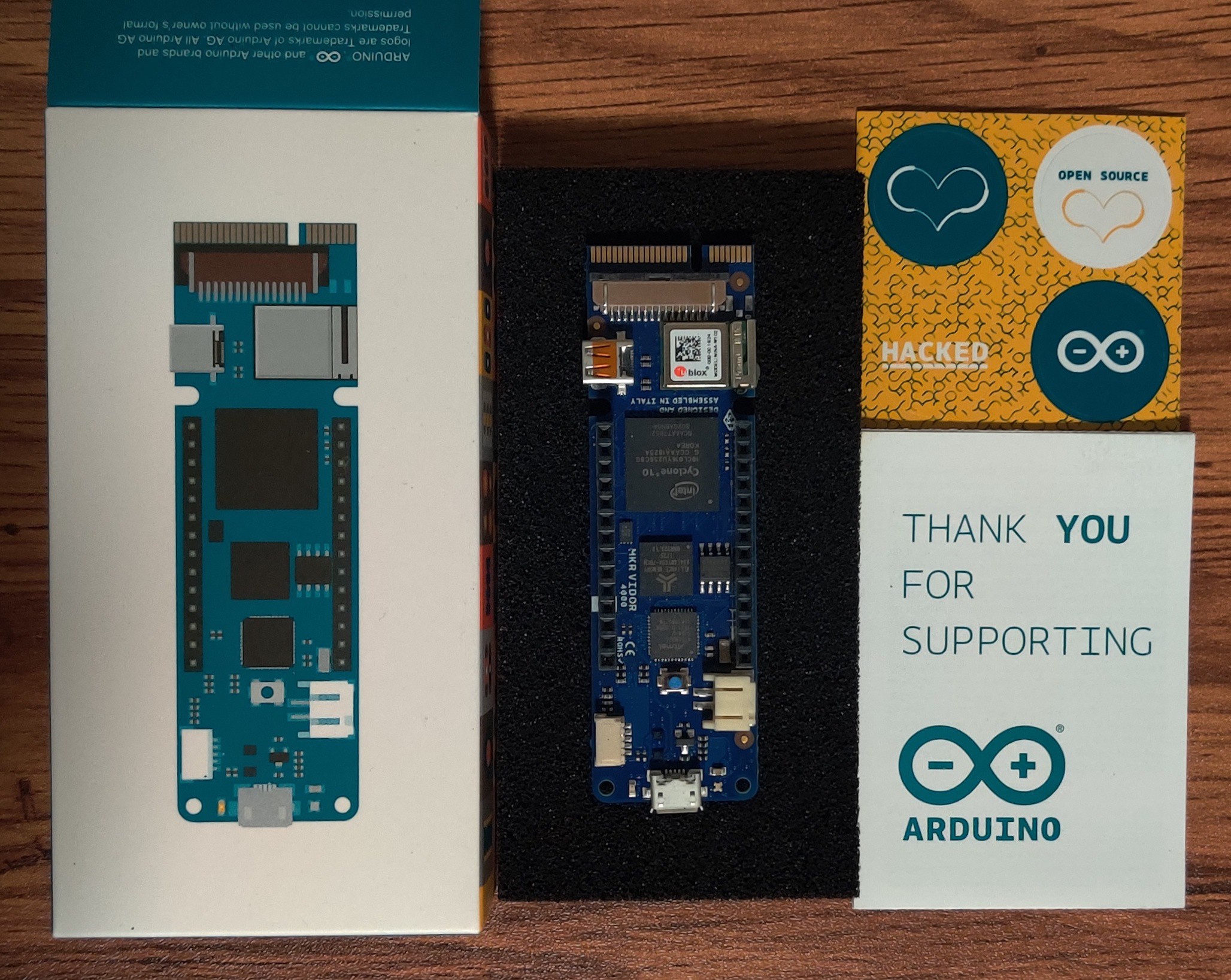
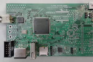
Since this project is intended to be used with any operating system, the initial target will be the Lattice iCE40 series since Project IceStorm is the only tool that runs on multiple operating systems. IceStorm currently supports the iCE40 HX1K, HX8K, and UltraPlus. The initial version of the FPGA-Helper board will be able to connect directly to the following boards:
Programming (SPI):
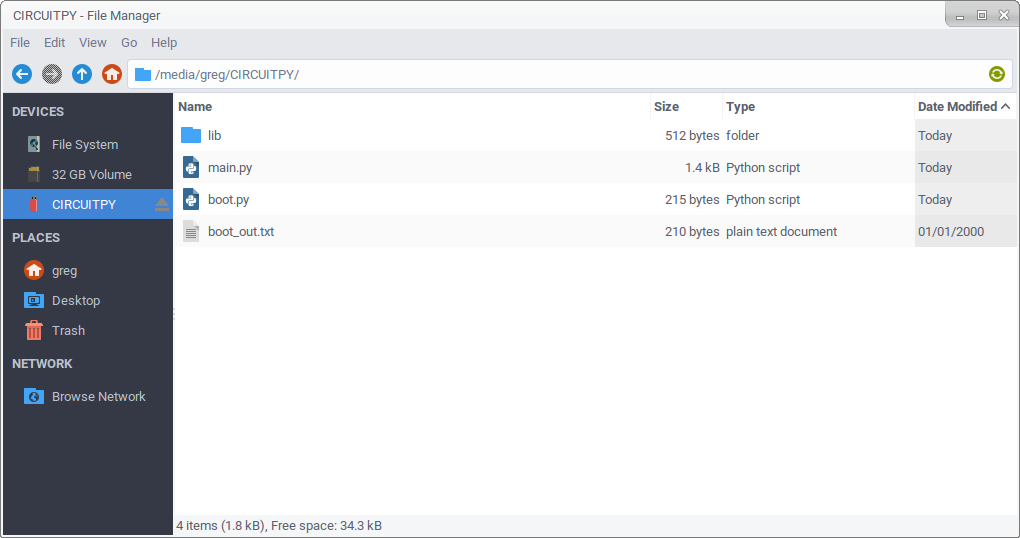
In order to provide "Adafruit easy" programming on multiple operating systems, the FPGA-Helper will allow for drag-n-drop programming using USB Flashing Format (UF2). The initial version of the board has an SOIC 8 location that can be loaded with a larger flash device to allow for upgrading the size of the flash provided on the target board.
USB Communication (UART):
The FPGA-Helper will implement a standard USB-CDC virtual serial port that can be used for communication between the FPGA and a computer.
Analog I/O (I2C):
The FPGA-Helper will implement the seesaw protocol to give the FPGA access to additional peripherals in the programmer MCU.

 Martin Cejp
 Alex
Alex
 Luke Valenty
 Chance Reimer