Close
0%
0%

micropower micrologger [mPmL]

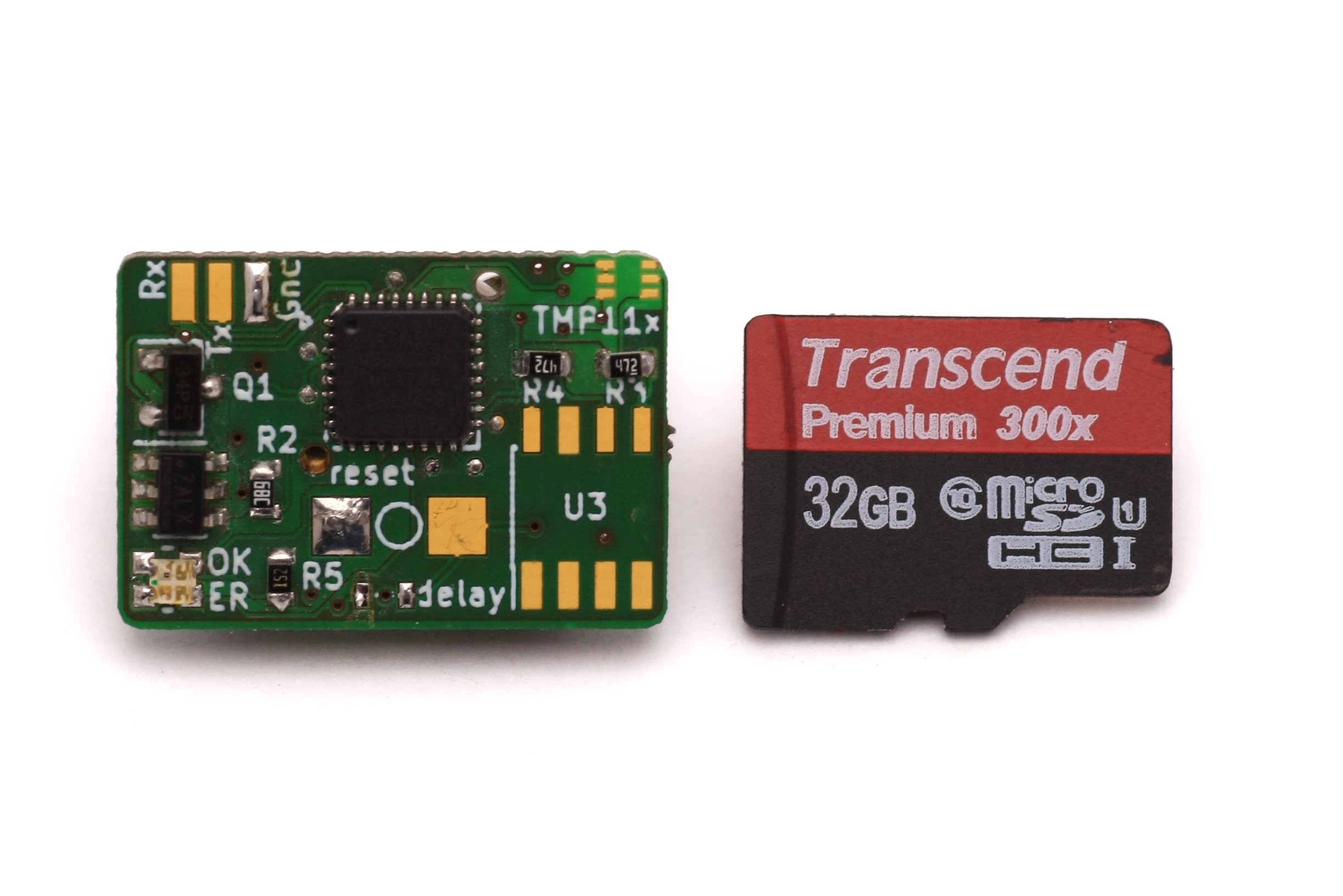
A set-and-forget I2C/digital datalogger. Size: 25.3x 18x 10mm incl. battery. Runtime: > 1year

janJan
Similar projects worth following
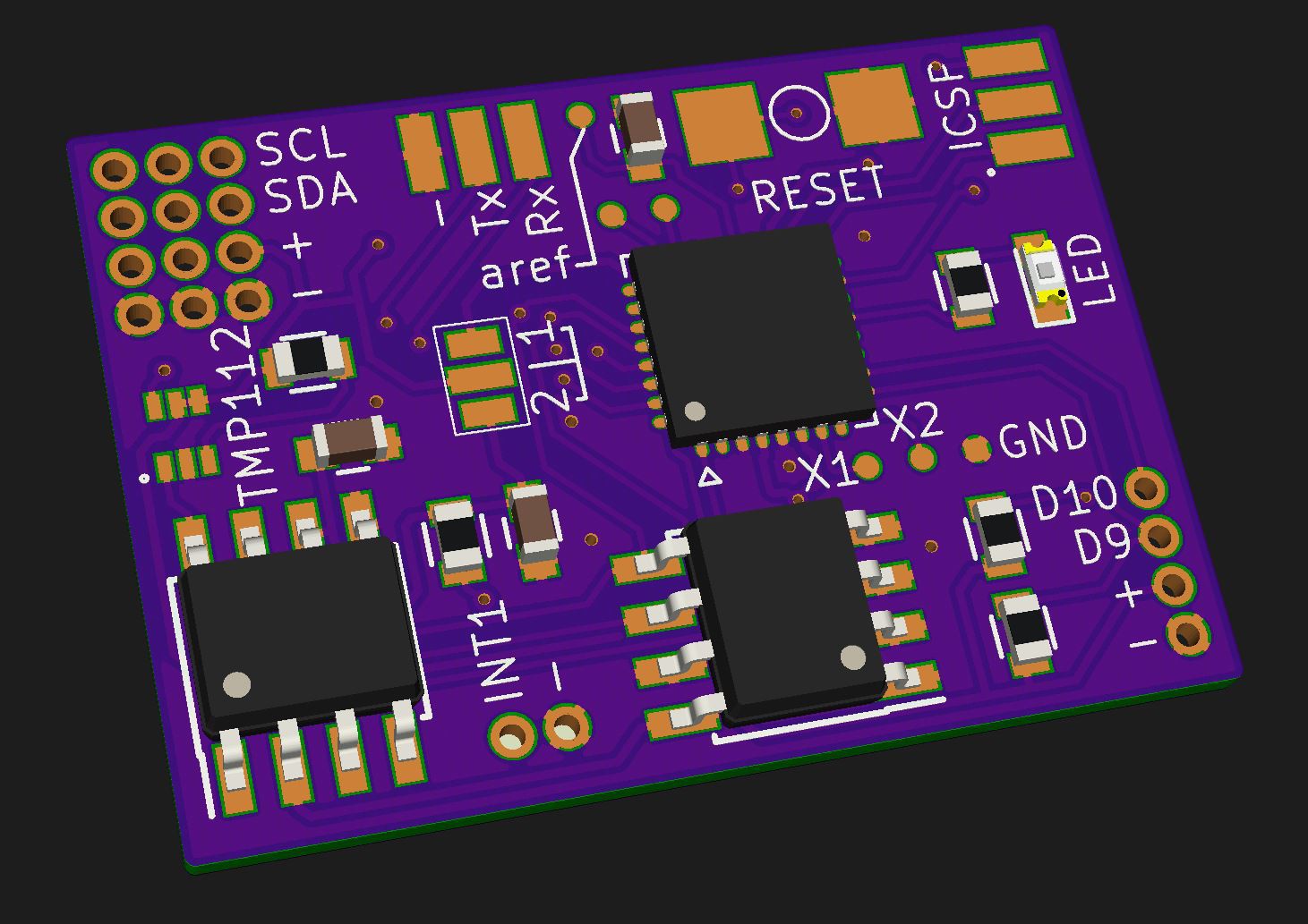
This is a logical development from my first and second logger projects. The idea is simple: The logger needs to be small enough to fit inside small spaces, e.g. a bee hive.
With the press off a button it starts/stops logging. The casing can be as simple as shrink tubing!

You can find the original project here.

Features at a glance

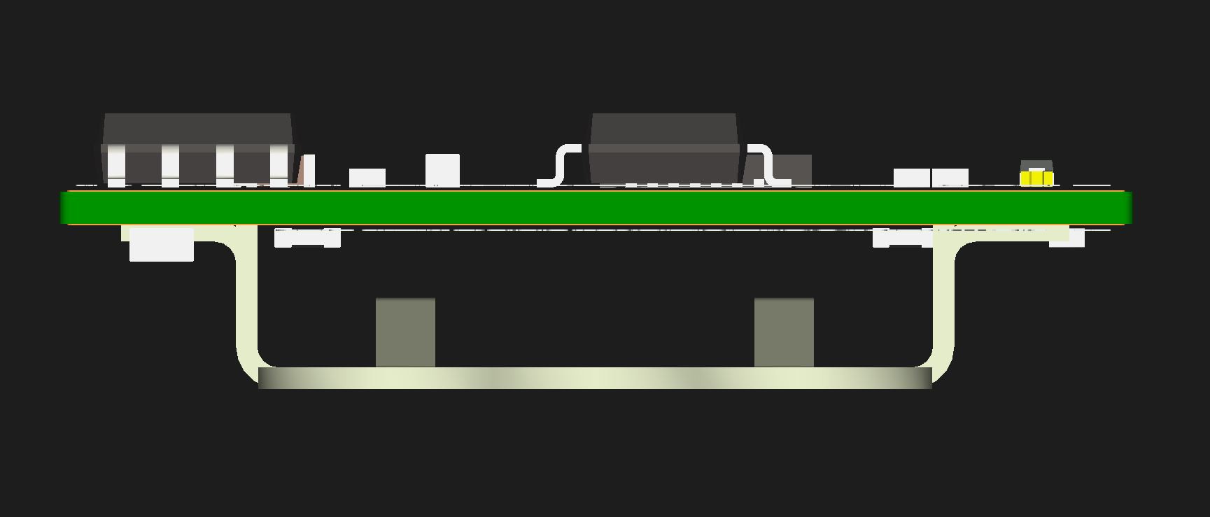
  • small: only 25.3x18x8mm incl. battery holder
  • low power: runtime 2 years (with a CR1632 120mAh coin cell, 4 logs/hr)
  • versatile: use I2C or digital sensors (board runs from 3.3 to 1.8V)
  • 1x temperature sensor on-board, accuracy ± 0.5°C (TMP112, NIST-traceable)
  • data retention > 200 years (depends on EEPROM manufacturer)
  • data transfer via standard 9600 baud serial protocol (or faster, you decide!)

Functional specification

The following table shows the most important features I expect from my logger. There are of course more (e.g. LED for signaling, reset button, ...) but those will make it into the final design anyway!

PARAMETERVALUE/DATAIMPORTANCESTATUS
size
≤25.4x25.4mm (1 square inch)
(preferably 25x20mm)
height < 10mm
REQUIRED
DESIRED
DESIRED


operational life
> 1 year on a CR1225 button cell (48mAh)
> 2 years on a CR1632 button cell (120mAh)
REQUIRED
DESIRED

RTCtemp. compensated RTC (DS3231MZ+)
REQUIRED
accuracyT ± 0.5°C
REQUIRED
ext. sensor size
small for hive "in cell" measurement
DESIRED
memory(timestamp + 4x temperature) * 1 year
REQUIRED(✔)
easy data transfer
3 wire interface (RX, TX, GND)
REQUIRED

Here's a quick jump-to to all of my log entries (latest changes are bold):

ENTRYLAST CHANGED
01 – choice of components
Tuesday, Oct. 2nd, 2018
02 – data storage
calendar week 39
03 – test placement of componentsWednesday, Oct. 10th, 2018
04 – logger and sensor positionSaturday, Aug. 18th, 2018
05 – PCB finalizedSunday, Aug. 19th, 2018
06 – PCB finalized again and orderedMonday, Aug. 20th, 2018
07 – shitty TMP11x breakout boardsMonday, Aug. 20th, 2018
08 – my own deadline + thoughts on suppliersThursday, Aug. 23rd, 2018
09 – it's alive!Saturday, Sept. 22nd, 2018
10 – usagecalendar week 39
11 – final picturesSaturday, Sept. 29th, 2018
12 – soldering 1.6x1.6mm (SOT-563) sensors to leadsMonday, Oct. 8th, 2018

mPmL_basicLogger_works_2018-10-03_2055.zip

Just a first version of the logger-code which works. Its far from perfect and even more far from done. But hey, it works for now. Nev revisions coming soon!

x-zip-compressed - 9.21 kB - 10/03/2018 at 19:16

Download

FirstDemo.mp4

Quick demo showing an early stage of the logger.

MPEG-4 Video - 31.69 MB - 10/01/2018 at 12:59

Download

mPmL_EEPROM_test.zip

code to read temperatures from the TMP11x sensor and write three blocks to the EEPROM. It reads them back over serial to verify your data

x-zip-compressed - 2.47 kB - 09/29/2018 at 10:37

Download

mPmL_setRTC_over_Serial.zip

code to set the DS3231M RTC. Uses https://github.com/JChristensen/DS3232RTC. See examples from that library to use/set the alarms etc as well!

x-zip-compressed - 2.13 kB - 09/23/2018 at 08:13

Download

mPmL_BlinkPowerDown.zip

code to test the onboard LED. features rocketscreams low power library to save precious power while doing nothing between LED flashes :)

x-zip-compressed - 1.06 kB - 09/22/2018 at 15:04

Download

View all 7 files

  • 1 × Atmega328P-MU Microprocessors, Microcontrollers, DSPs / ARM, RISC-Based Microcontrollers
  • 1 × TMP112 0,5°C onboard temperature sensor
  • 1 × DS3231M (SOIC8 package) Clock and Timer ICs / Real-Time Clocks
  • 1 × M24M02 Memory ICs / EEPROMs, alternatives are e.g. 24LC512, 24AA512, ...
  • 1 × Keystone 3012 button cell holder for CR16XX cells

View all 10 components

  • Next stop: 18x13x6mm. 35nA (0.000035mA) sleep current.

    Jan02/25/2019 at 18:12 0 comments

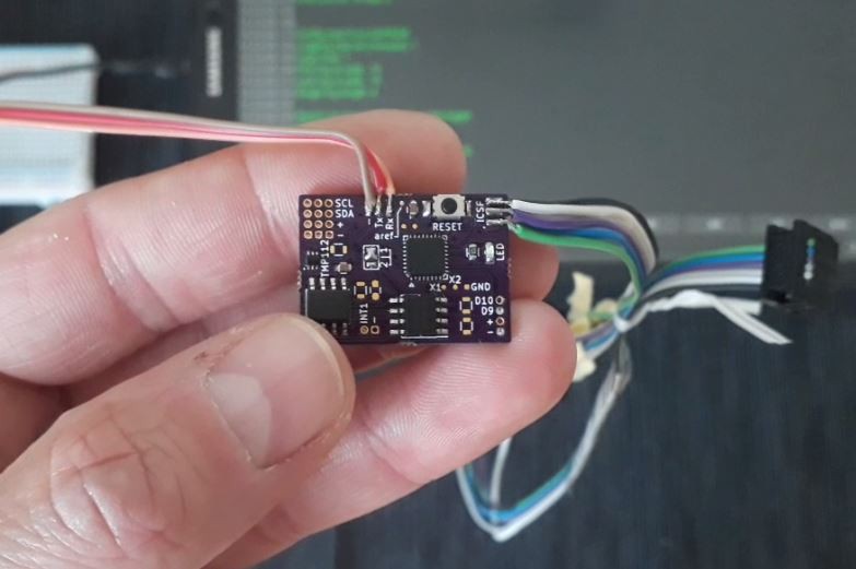
    The micropower micrologger project is not dead. Quite the contrary is true. I've been testing this even smaller logger for a while now, in a basic (not fully assembled) variant:

    It is working well. Power source is a CR1225 (on the back of the PCB). The timing is not done with an RTC but an TPL5110 nanopower timer. The next version will be even smaller, as I found a smaller battery holder from Linx Technology. The reset button will be removed as well.

    The board uses 35nA in shutdown mode. The TPL5110 is activated at a set intervall and powers up the whole board. The Atmega does its job and sends an signal to turn off to the TPL5110 chip, when done.

    Timing is only accurate to a few seconds (details see the datasheet!) due to being set by a resistor. But for this type of logger, the exact time is not critical.

    The EEPROM will be a 2Mbit one, the sensor is the really small TMP112. Just recently @Edward Mallon posted a guide to use an onboard crystal/oscillator to measure temperatures. For this small logger this looks like an cool approach to save some money on the sensor (around 90 cents). But it needs per-logger adjustments, so I am not sure yet...

  • 12 – soldering 1.6x1.6mm (SOT-563) sensors to leads

    Jan10/08/2018 at 18:23 4 comments

    TL;DR it is possible by hand

    HOW TO

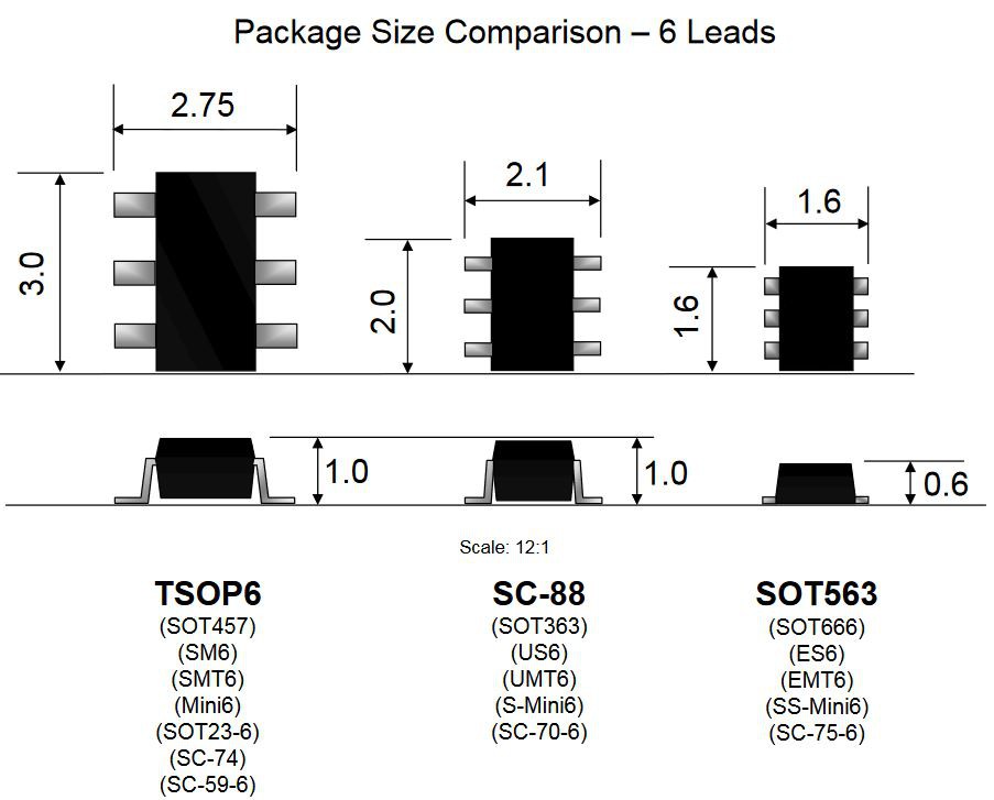
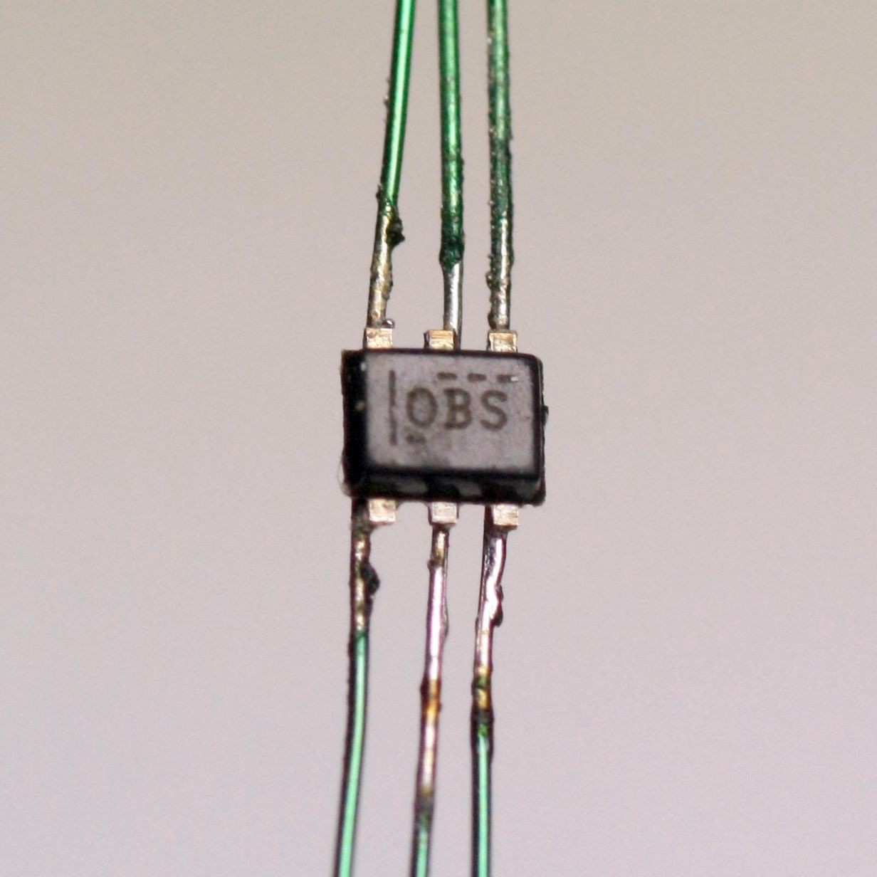
    Here is my first try soldering 0.15mm (0,0059") wire to a TMP112 sensor. These come in an SOT-563 package with 0.5mm pitch.

    Copyright ON-Semi


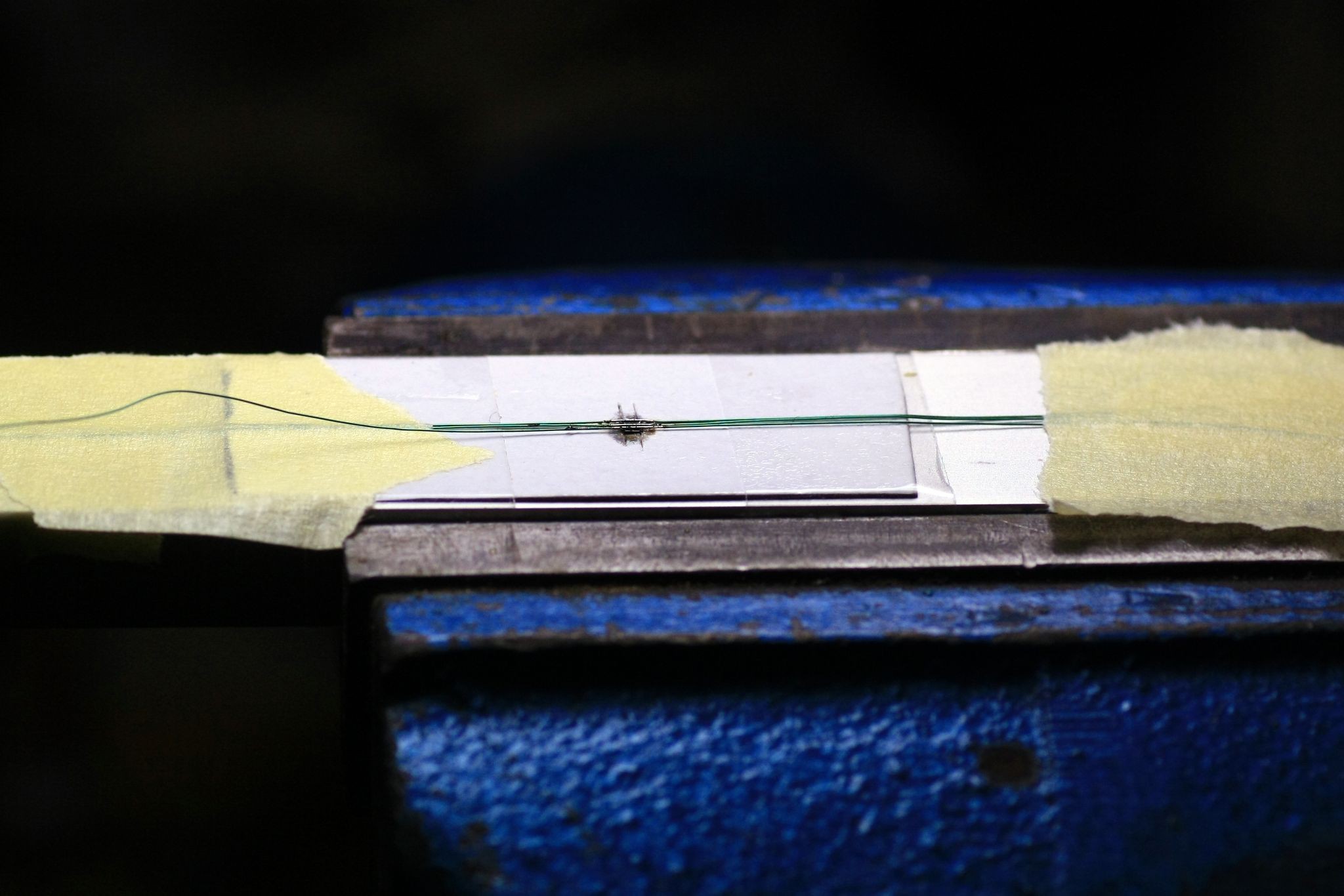
    I made a cutout in a piece of cardboard, glued it to a piece of aluminum (we know it's aluminium, right?) and tried soldering wires to it. Worked OK, though I had to use a really fine tip for that. Took me around 10 minutes.

    sketchy setup but it worked

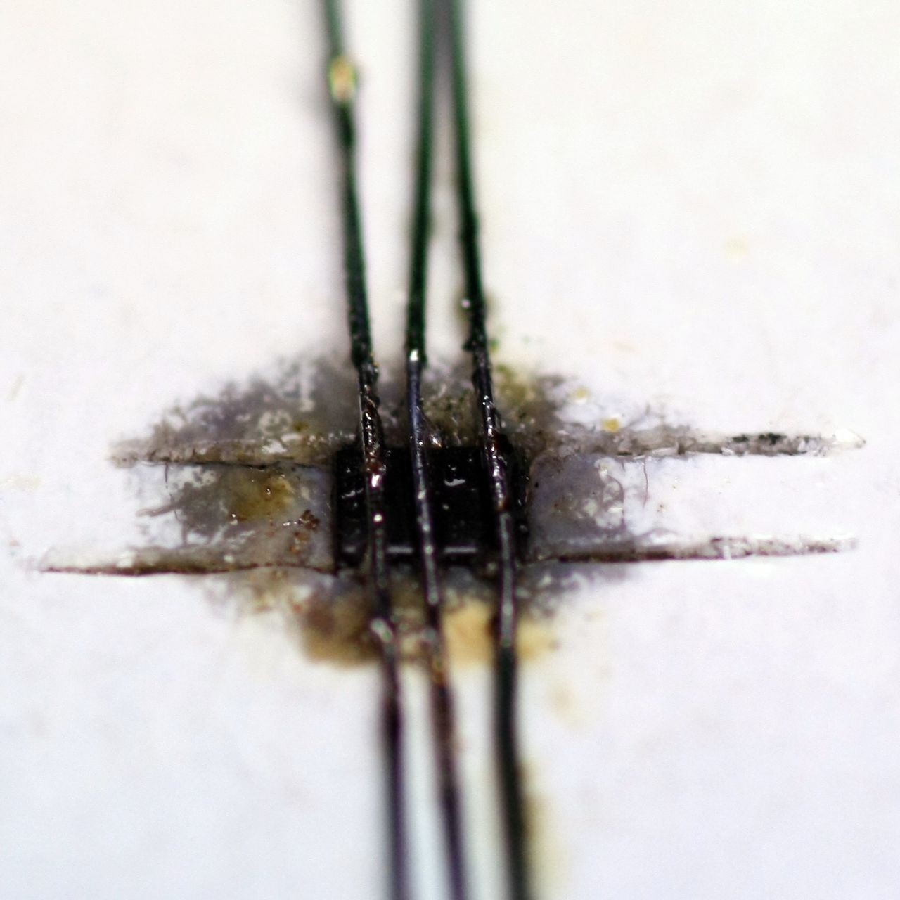
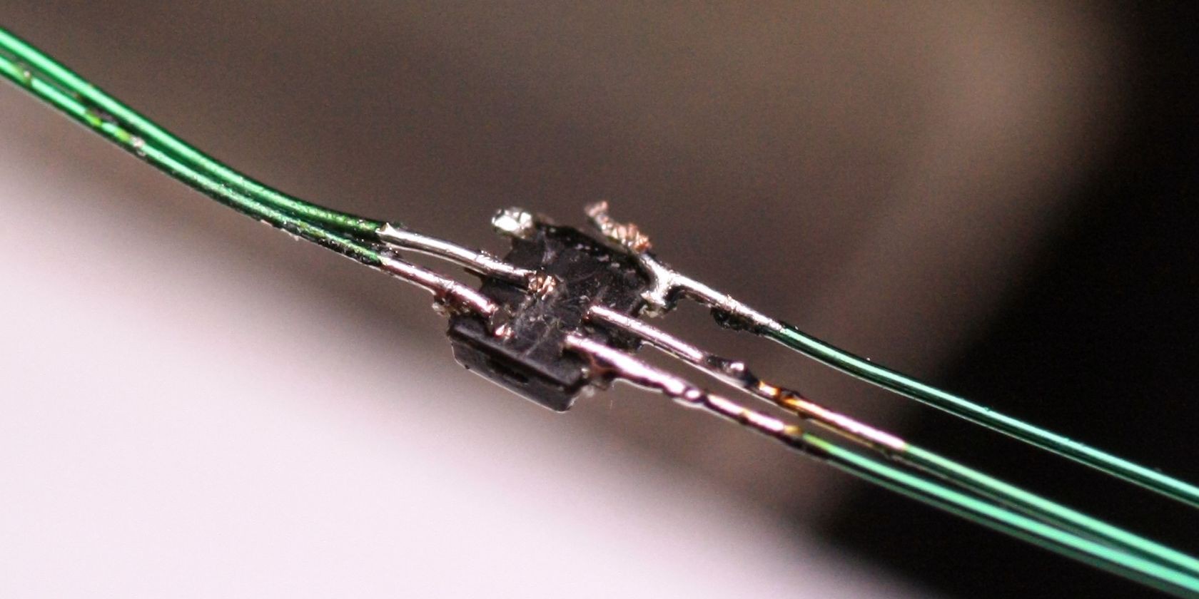
    The main problem is, the wire lengthens a bit while soldering, so it easily slides off the pad. Should I need to solder a few of them I need to add a weight or spring to one side which compensates for that.

    directly after soldering

    After cleaning a bit, this is what I ended up with:

    Of course opposite pins are still connected to each other, but that will be corrected when doing my next tests with a better setup. I think I know how this will work much better...

    BTW: Cutting the leads in between with a side-cutter didn't work well (topmost contacts), using a cutter knife does a good job though:

  • 11 – final pictures

    Jan09/29/2018 at 13:11 0 comments

    Updated – 01.10.2018

    Here's a short video of the working logger.

    click to play in new tab (hosted @hackaday.io, not youtube)
    Read more »

  • 09 – it's alive!

    Jan08/27/2018 at 14:11 0 comments

    Update – 22.09.18

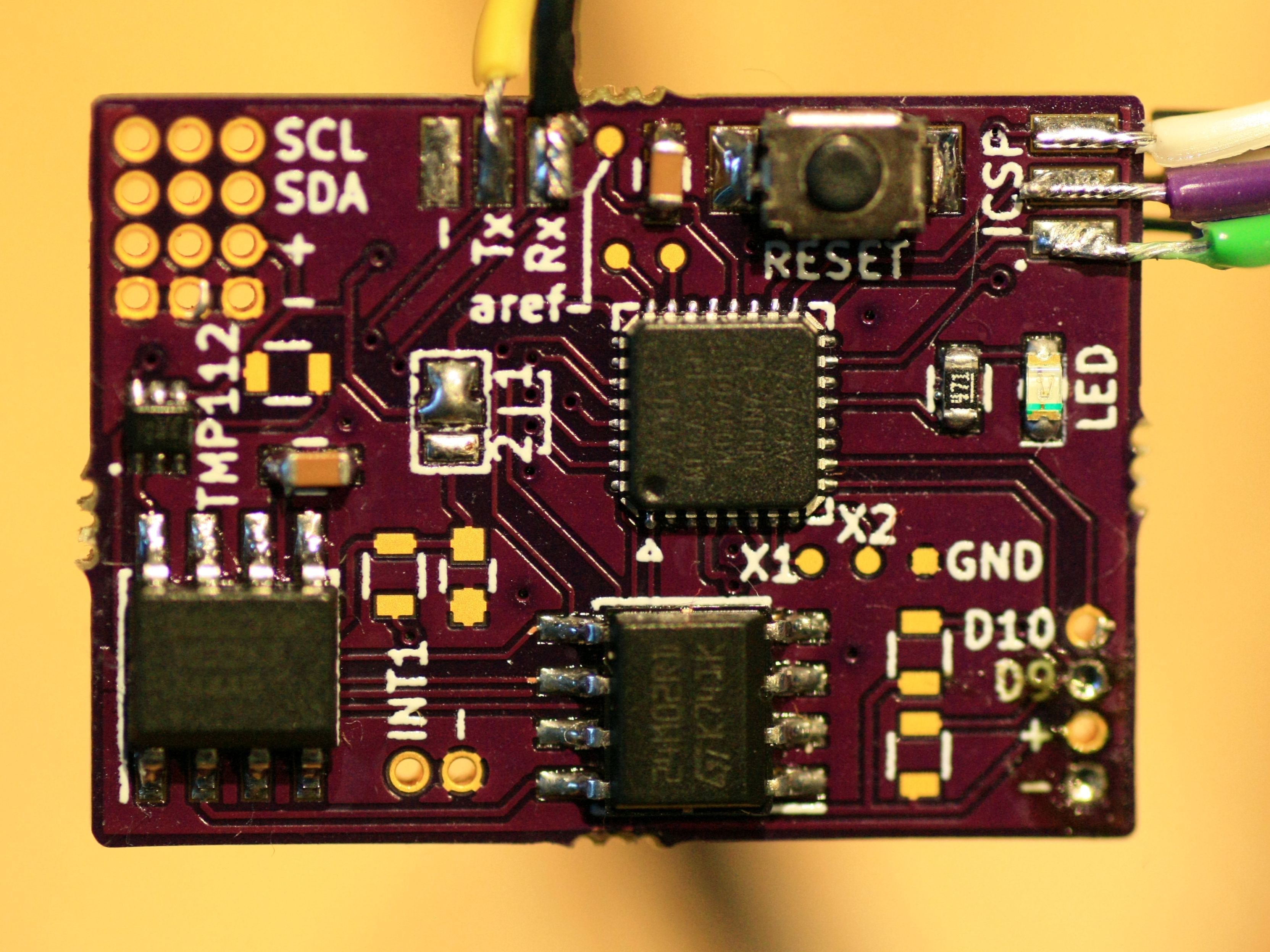
    I finally had the time to "fully" assemble everything. All things work as expected, RTC, EEPROM, LED, temperature sensor.

    A few components are extras and do not need to be placed!

    I will upload code snippets to test all the components, should anyone want to build that little thingy!

    Read more »

  • 08 – my own deadline + thoughts on suppliers

    Jan08/23/2018 at 06:30 0 comments

    Update 01.09.2018 – Project halted for two weeks

    Fortunately, the deadline has been pushed to October. This is great news, as I won't find any time working on it the next two weeks. After that I'll complete it and present my fully populated board. It's just soldering the EEPROM, RTC and a few passives anyway.

    Read more »

  • 07 – shitty TMP11x breakout boards

    Jan08/20/2018 at 20:38 2 comments

    As I need to try and connect up to four TMP112 sensors to my logger, I decided to make some breakout boards for them. Individual board will be around 6.5x3.5mm.

    Address can be changed to one of 4 hex-values by a multi-solder bridge. I did not do fancy panelizing, instead I just chose 0.8mm board and added silkscreen lines where I need to cut the boards with a Dremel or knife:


    [+/-/C/D] are the I2C connections, [1/2/3/4] is the address select solder bridge (connect one of them to the longer middle pad) and on the other side is the SOT563 pad with longer pads for easier hand soldering. I'll use a hot air station anyway.
    There's space around the lines so I can use up to 1mm cutting disks without damaging the traces.

  • 06 – PCB finalized again and ordered

    Jan08/20/2018 at 18:53 0 comments

    So, even "final" PCBs are never finished. Just slept over it a night and added this and that, removed this and that as well.

    I ordered them at @oshpark today. Material will be 0.8mm thick, with 2oz copper.

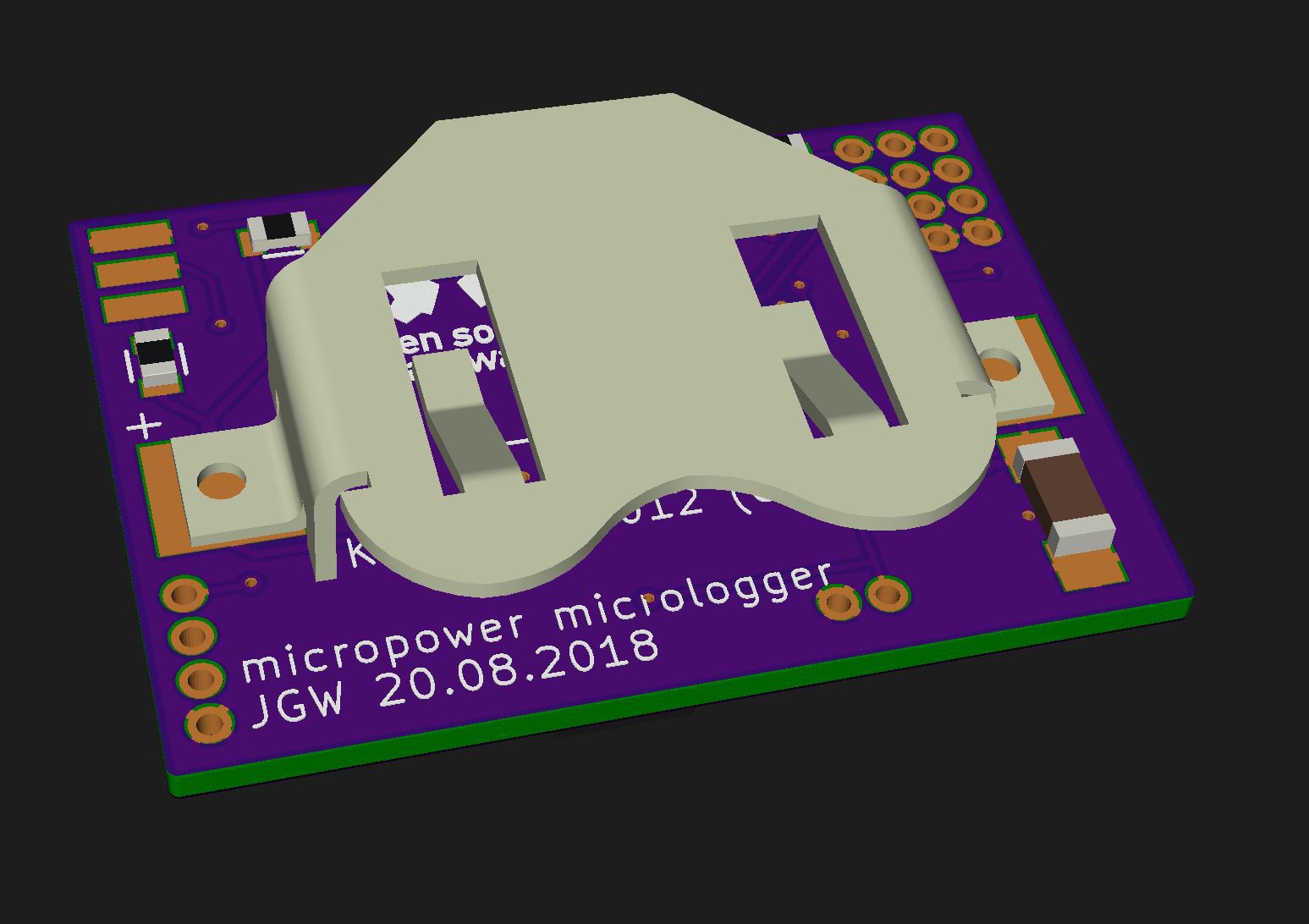
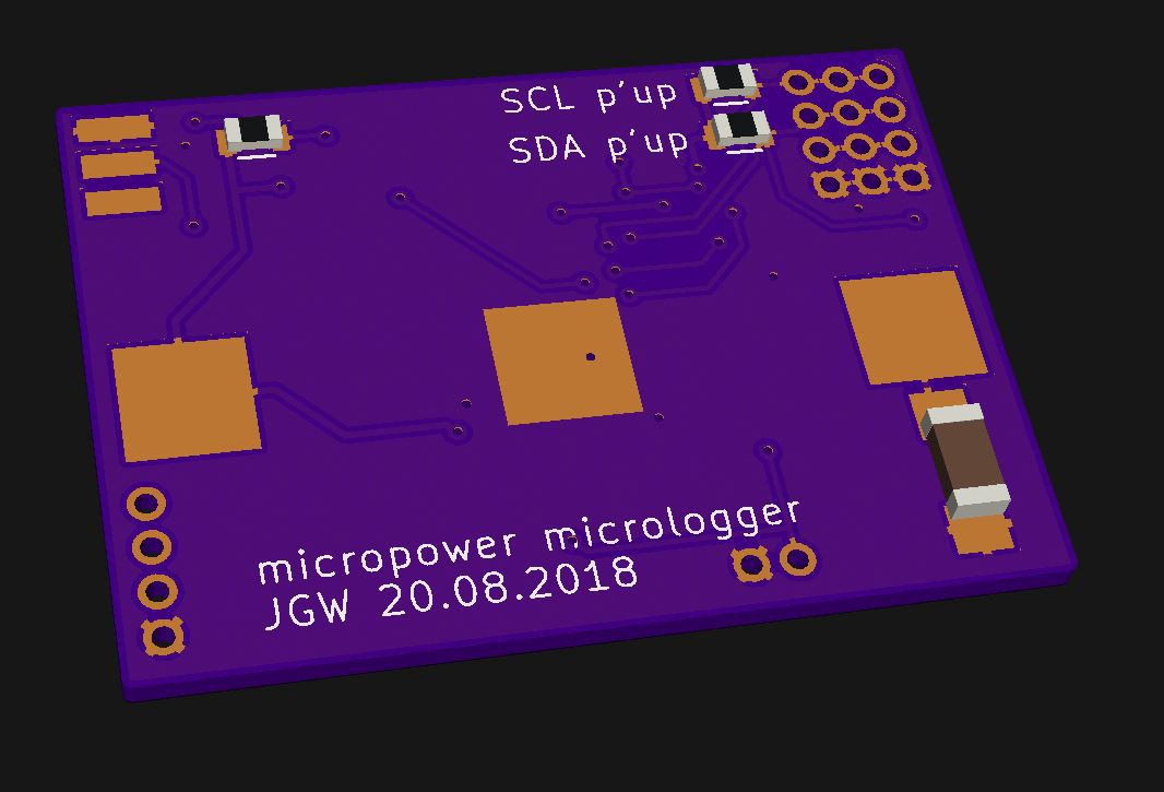
    I couldn't find a free to download model of the keystone 3012 battery holder, so I made one myself. This was quicker than registering somewhere and downloading it :)

    It's not 100% to spec, but the outer dimensions are correct, that's what I wanted.

  • 05 – PCB finalized

    Jan08/18/2018 at 13:53 0 comments

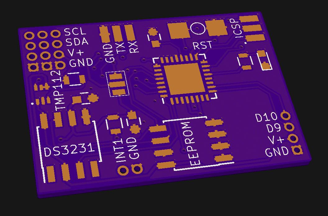
    Update 19.08.2018 – PCB is done

    Read more »

  • 04 – logger and sensor position

    Jan08/12/2018 at 13:23 0 comments

    Update 10.10.2018 - sensor glued into comb for test purposes

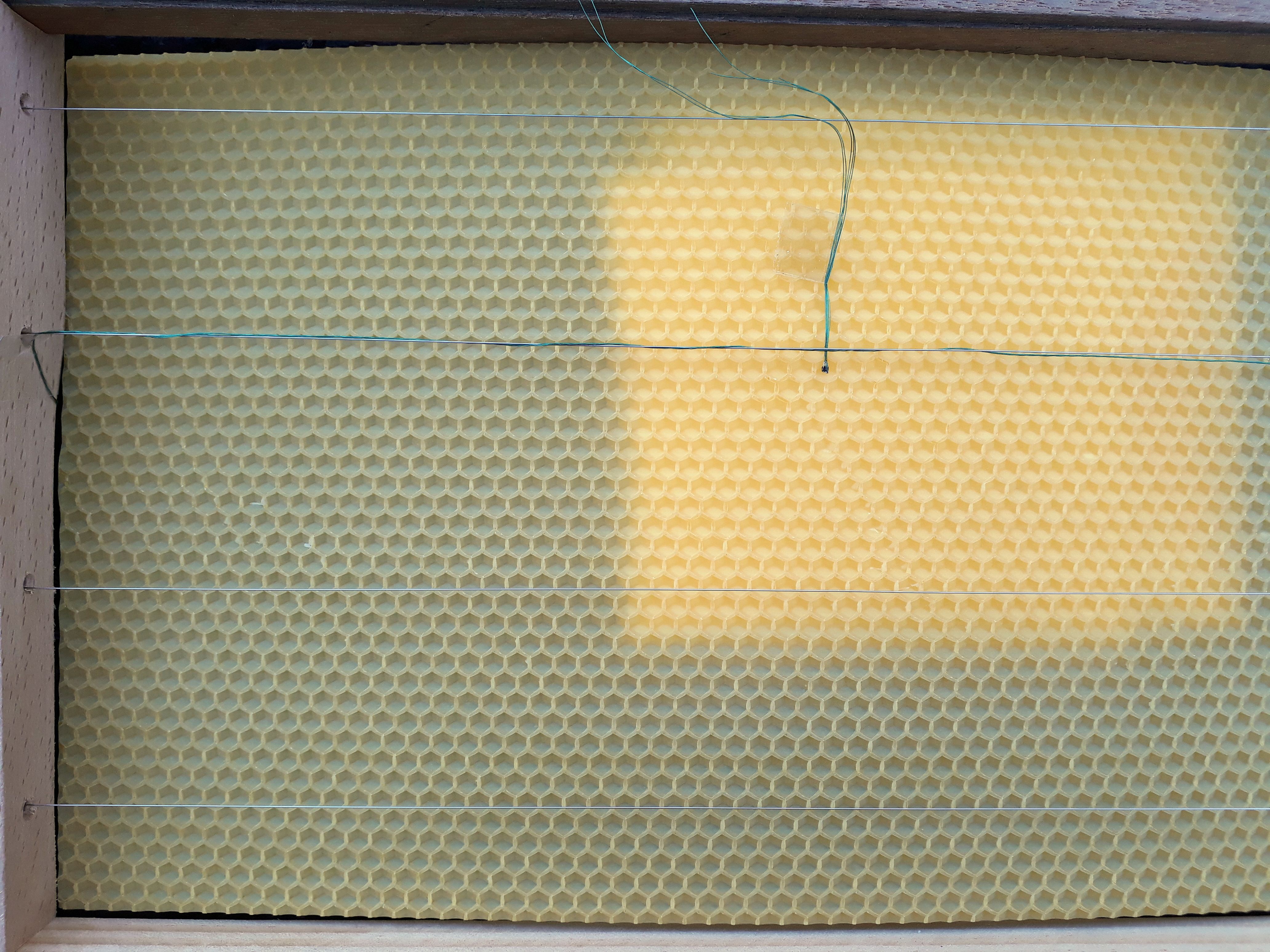
    Today I tried "melting in" a sensor into a pre-formed comb / foundation. The 4-stranded copper wire is wrapped around the stainless steel wire with 3 turns, then the wax foundation is laid on top of it. Later, the stainless wire is heated by putting some amps through it and the foundation sinks in a bit. (Haven't done this step here).

    What I have done is the wrapping part and aligning the test-sensor:

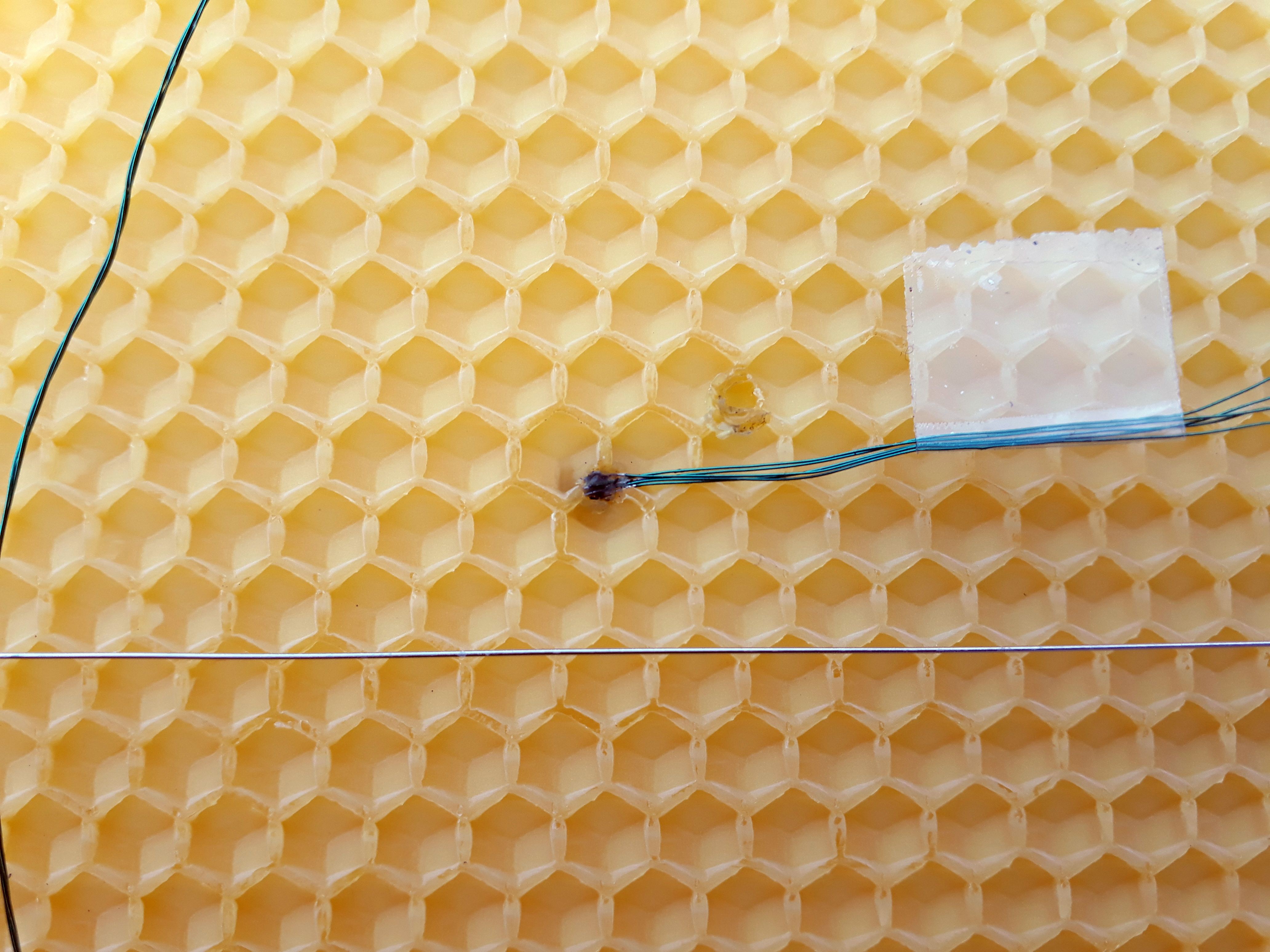
    Then I heated a small metal rod and pressed it on the sensor so it melts into the wax foundation:

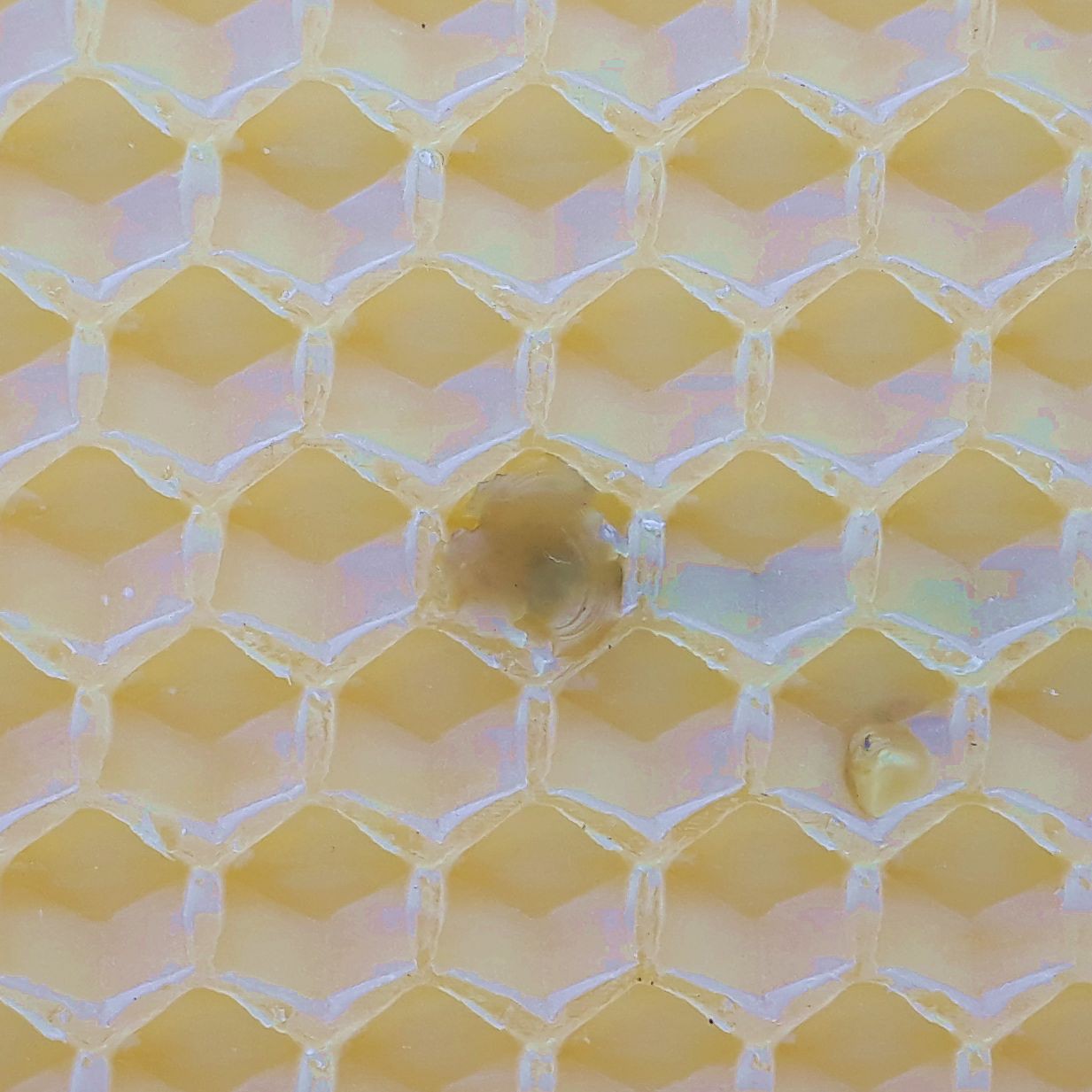
    The other side looks like this:

    I added a drop of molten wax so the bees won't abandon the cell because of a foreign body. Hope that'll do :)

    Read more »

  • 03 – test placement of components

    Jan08/11/2018 at 08:18 0 comments

    Edit August 15th, 2018: Parts ordered.

    All parts are ordered and are expected to arrive in around two weeks from china. I hope to finish my board this weekend to send it to the fab as well, so I can start my first assembly.

    The final design will look quite different from the mock-up...

    Read more »

View all 11 project logs

Enjoy this project?

Share

Discussions

greg davill wrote 10/01/2018 at 10:20 point

Neat project and nice execution!

  Are you sure? yes | no

Similar Projects

Does this project spark your interest?

Become a member to follow this project and never miss any updates