-
Next stop: 18x13x6mm. 35nA (0.000035mA) sleep current.
02/25/2019 at 18:12 • 0 commentsThe micropower micrologger project is not dead. Quite the contrary is true. I've been testing this even smaller logger for a while now, in a basic (not fully assembled) variant:
![]()
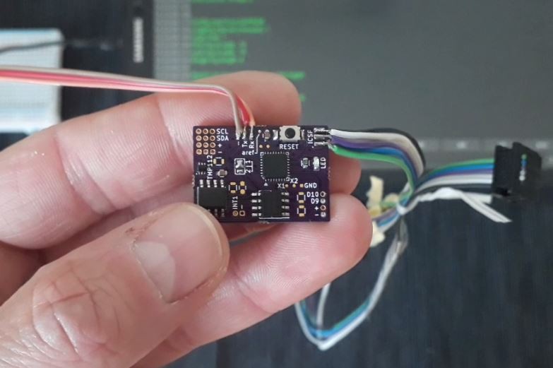
It is working well. Power source is a CR1225 (on the back of the PCB). The timing is not done with an RTC but an TPL5110 nanopower timer. The next version will be even smaller, as I found a smaller battery holder from Linx Technology. The reset button will be removed as well.
The board uses 35nA in shutdown mode. The TPL5110 is activated at a set intervall and powers up the whole board. The Atmega does its job and sends an signal to turn off to the TPL5110 chip, when done.
Timing is only accurate to a few seconds (details see the datasheet!) due to being set by a resistor. But for this type of logger, the exact time is not critical.
The EEPROM will be a 2Mbit one, the sensor is the really small TMP112. Just recently @Edward Mallon posted a guide to use an onboard crystal/oscillator to measure temperatures. For this small logger this looks like an cool approach to save some money on the sensor (around 90 cents). But it needs per-logger adjustments, so I am not sure yet...
-
12 – soldering 1.6x1.6mm (SOT-563) sensors to leads
10/08/2018 at 18:23 • 4 commentsTL;DR it is possible by hand
![]() HOW TO
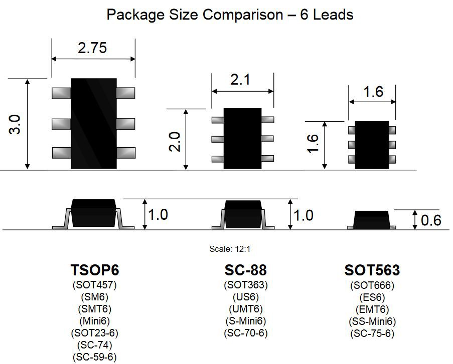
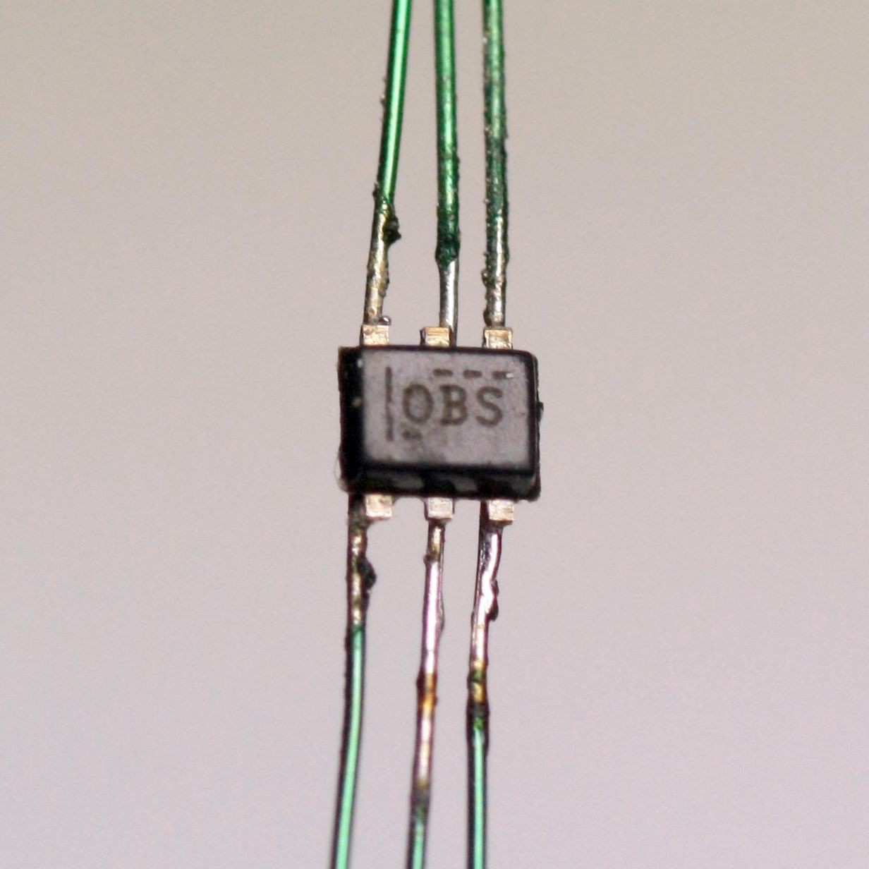
HOW TOHere is my first try soldering 0.15mm (0,0059") wire to a TMP112 sensor. These come in an SOT-563 package with 0.5mm pitch.
Copyright ON-Semi
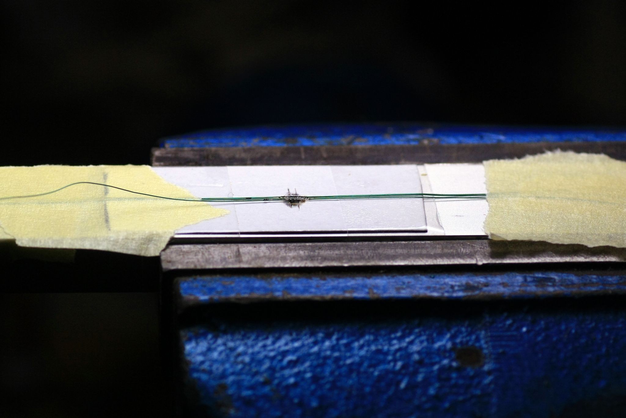
I made a cutout in a piece of cardboard, glued it to a piece of aluminum (we know it's aluminium, right?) and tried soldering wires to it. Worked OK, though I had to use a really fine tip for that. Took me around 10 minutes.![]()
sketchy setup but it worked The main problem is, the wire lengthens a bit while soldering, so it easily slides off the pad. Should I need to solder a few of them I need to add a weight or spring to one side which compensates for that.
![]()
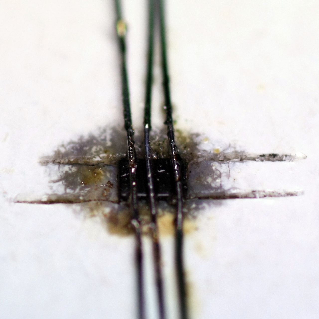
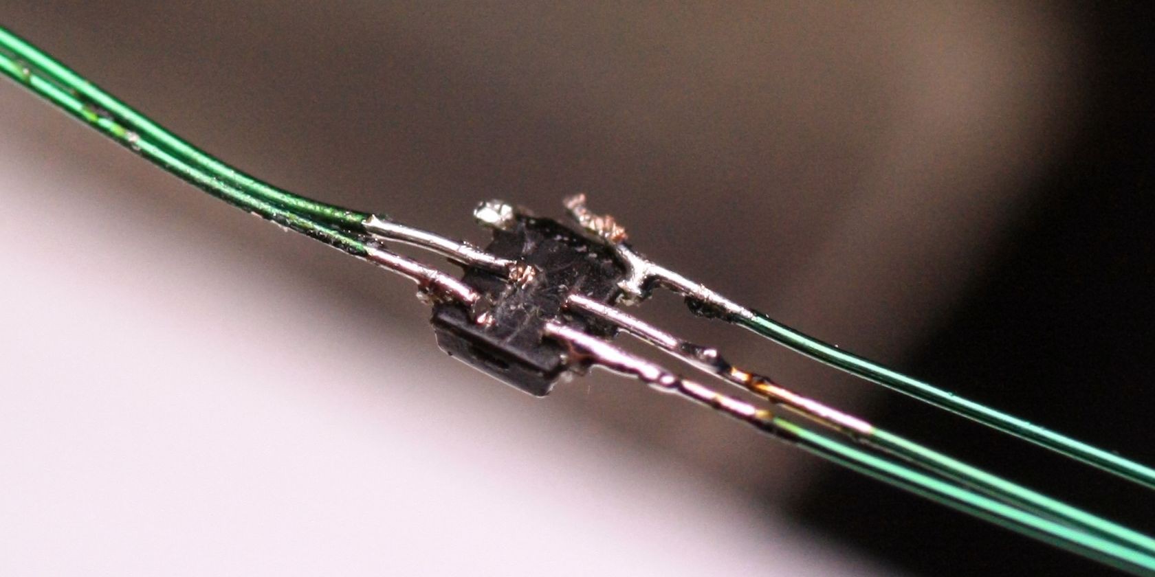
directly after soldering After cleaning a bit, this is what I ended up with:
![]()
Of course opposite pins are still connected to each other, but that will be corrected when doing my next tests with a better setup. I think I know how this will work much better...
BTW: Cutting the leads in between with a side-cutter didn't work well (topmost contacts), using a cutter knife does a good job though:
![]()
-
11 – final pictures
09/29/2018 at 13:11 • 0 commentsUpdated – 01.10.2018
Here's a short video of the working logger.
click to play in new tab (hosted @hackaday.io, not youtube) ---------- more ----------Heeeeere we go!
Here are the final pictures of the device. What's missing in the pictures is the external sensor. The unit is fully functional nonetheless. I'll try to solder one external sensor in time to add a photo of that too.
![]()
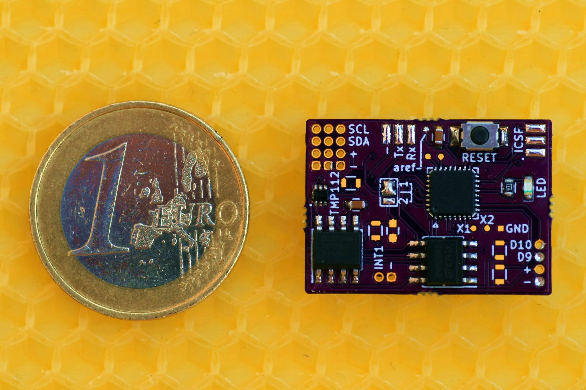
mPmL - size compared to 1€ coin ![]()
mPmL - in shrink tubing ![]()
mPmL - built into frame ![]()
mPmL - built into frame. can't see it from above. exactly what we want! ![]()
comparison between versions. top to bottom: V1.1, V1.2, mPmL -
09 – it's alive!
08/27/2018 at 14:11 • 0 commentsUpdate – 22.09.18
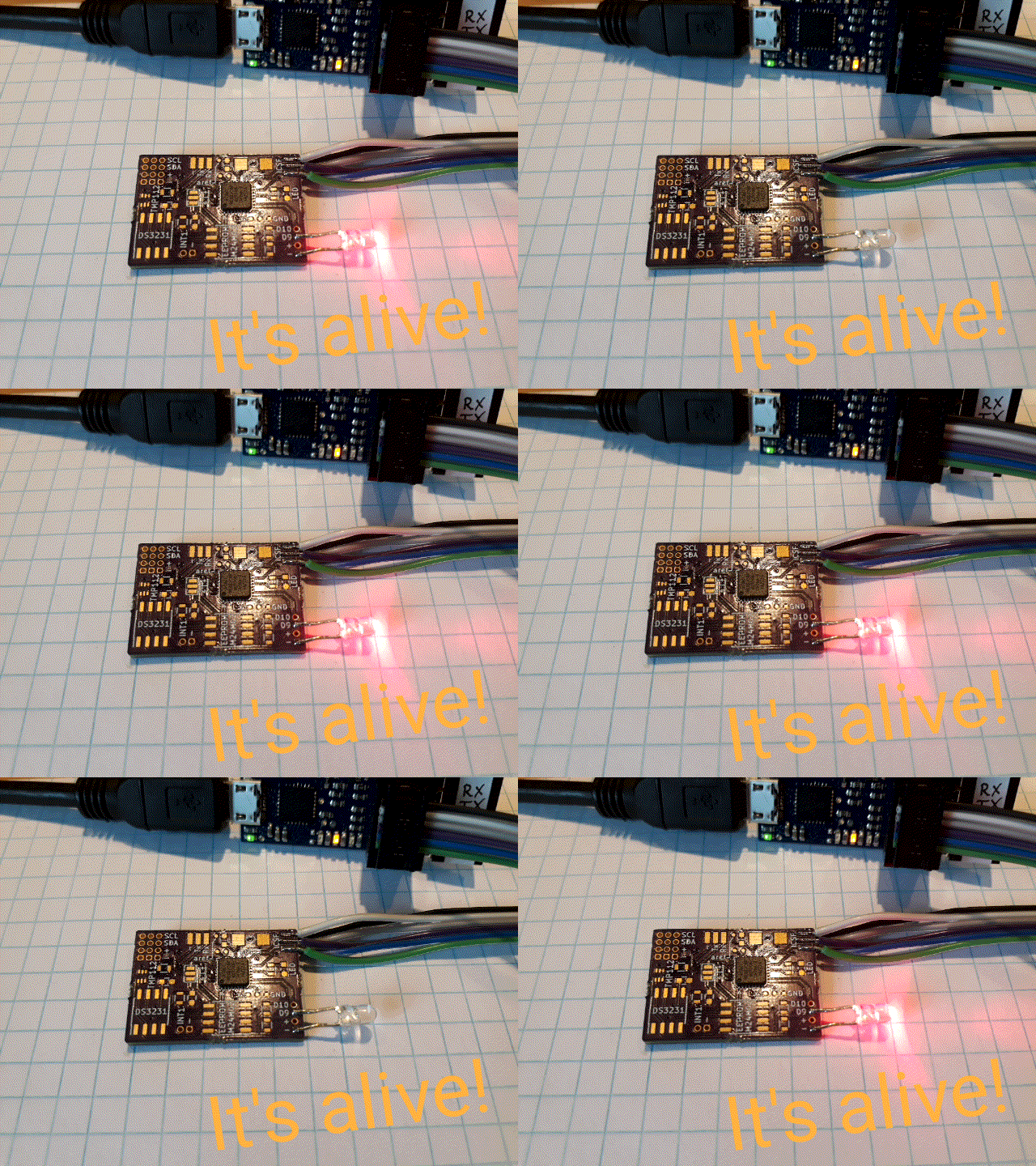
![]()
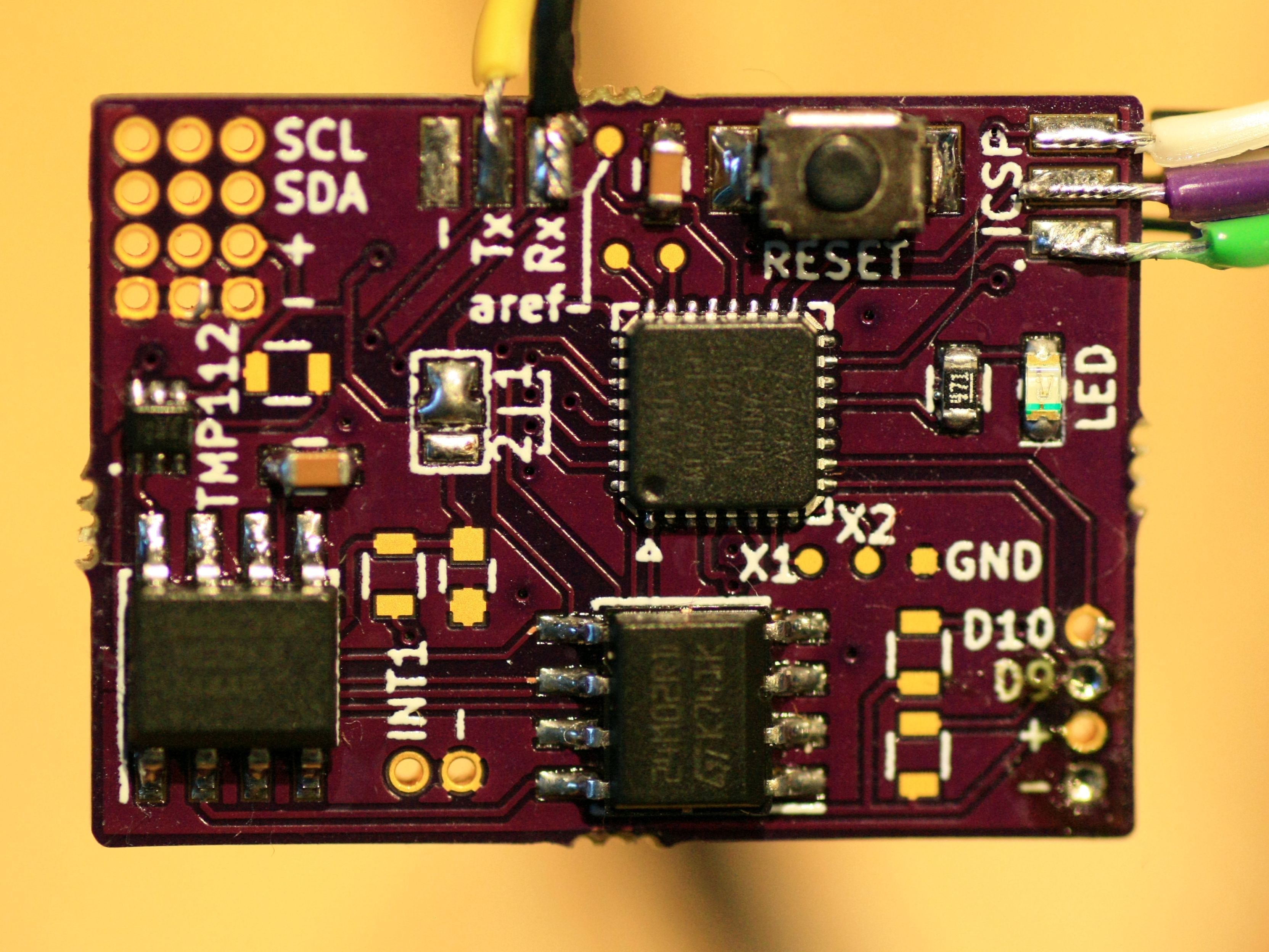
I finally had the time to "fully" assemble everything. All things work as expected, RTC, EEPROM, LED, temperature sensor.
A few components are extras and do not need to be placed!
I will upload code snippets to test all the components, should anyone want to build that little thingy!
---------- more ----------My boards arrived from the US just a few days after I sent the files.
They look fabulous, quality is really good. They're 1.6mm instead of 0.8 as I mentioned in a log before, but that's not a problem at all.
One stupid mistake is that I labeled D5 and D6 as D9 and D10. But other than the wrong silkscreen there's no downside to it...
![]()
I soldered just the Atmega and a LED, flashed the chip to use the internal resonator and uploaded the blink sketch which I set to 100ms because I drive the LED directly with no resistor.
Works like a charm, even after reflowing the chip 3 times @230°C because it didn't settle on it's pads correctly.
Can't solder the other stuff yet because I need to solder the TMP112 first and it has not arrived yet.
Stay tuned :)
-
08 – my own deadline + thoughts on suppliers
08/23/2018 at 06:30 • 0 commentsUpdate 01.09.2018 – Project halted for two weeks
Fortunately, the deadline has been pushed to October. This is great news, as I won't find any time working on it the next two weeks. After that I'll complete it and present my fully populated board. It's just soldering the EEPROM, RTC and a few passives anyway.
---------- more ----------I started working on this little thing just the moment the contest was made public. As someone mentioned already, the deadline really is a bit harsh on us. I mean, ordering parts may be possible quickly via digikey, farnell etc, but getting PCBs that fast can be quite the hassle, right? Plus you have to think about stuff and create the PCB before that...
So, as my project is mainly a shrink-it-down thing from my previous loggers, I managed to get things done quickly this time. Deadlines really help me with that sometimes!
Here's what really helped me getting stuff done:
- setting my own deadline at Friday 31, August 2018.
I'll be on vacation when the real deadline hits, so I needed to get it done before that - doing a few sketches and lists, what the thing really needs to do
no feature creep this time! I even removed some from the final board - keeping in mind what needs to be ordered first
PCBs usually need longer than parts! - setting a reminder on my phone to work regularly on that project.
Now on the PCB ordering part I really want to thank @oshpark for upgrading me to super swift service! I need to have the PCB assembled by 31.08.18 because after that I won't be able to do it, so I'd miss the contests goal.
The "down-side" is my boards will be 1.6mm thick. But his doesn't interfere with my goals, as overall the product is < 10mm in height.
Parts come from lcsc.com who have amazingly competitive prices. At digikey for example they charge you 18€ extra if your order is under 50€. What?! I can get all my stuff from lcsc for that money including shipping. For companies that's a no-brainer of course.
If they'd charge me the usual 5 to 8€ for shipping: fine. But 18€ handling for a small hand full of parts? No way for every small project I do.
So, will I meet the contests deadline?
I don't know but I hope so. My little project is far from complex and/or ground breaking. But shrinking the logger to fit inside a brood comb and even place a sensor inside a brood cell is something entirely new for me.
I'm looking at @Kris Winers sensor tile in awe and Pierce Nichols' CAN positioning motor controller which has to win (at least) the best documentation prize in my opinion! Two of many amazing submissions.
After all I did it (like all my projects) for the sheer fun of doing it.
Cheers, Jan
- setting my own deadline at Friday 31, August 2018.
-
07 – shitty TMP11x breakout boards
08/20/2018 at 20:38 • 2 commentsAs I need to try and connect up to four TMP112 sensors to my logger, I decided to make some breakout boards for them. Individual board will be around 6.5x3.5mm.
Address can be changed to one of 4 hex-values by a multi-solder bridge. I did not do fancy panelizing, instead I just chose 0.8mm board and added silkscreen lines where I need to cut the boards with a Dremel or knife:
[+/-/C/D] are the I2C connections, [1/2/3/4] is the address select solder bridge (connect one of them to the longer middle pad) and on the other side is the SOT563 pad with longer pads for easier hand soldering. I'll use a hot air station anyway.
There's space around the lines so I can use up to 1mm cutting disks without damaging the traces. -
06 – PCB finalized again and ordered
08/20/2018 at 18:53 • 0 commentsSo, even "final" PCBs are never finished. Just slept over it a night and added this and that, removed this and that as well.
I ordered them at @oshpark today. Material will be 0.8mm thick, with 2oz copper.
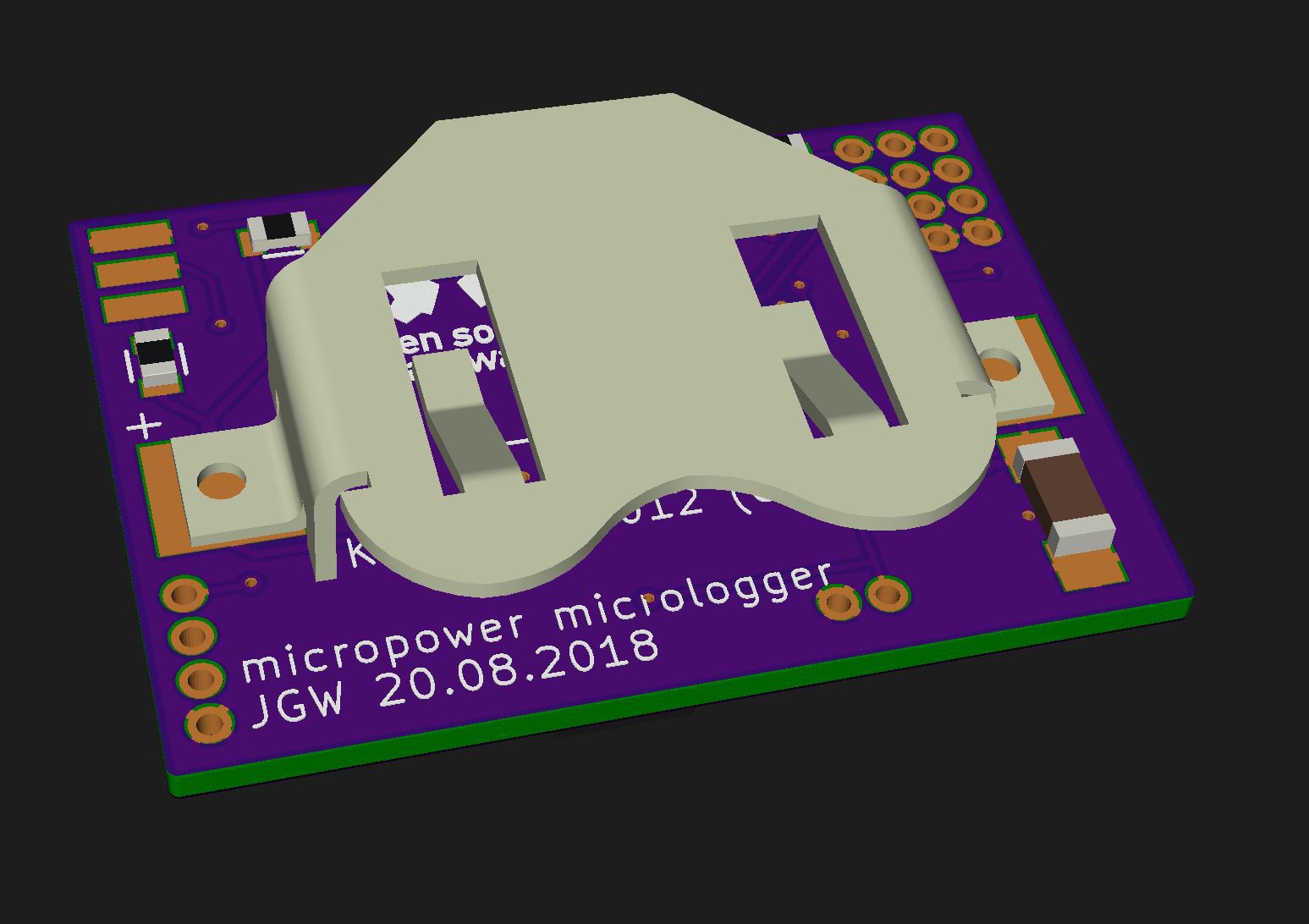
I couldn't find a free to download model of the keystone 3012 battery holder, so I made one myself. This was quicker than registering somewhere and downloading it :)
It's not 100% to spec, but the outer dimensions are correct, that's what I wanted.
-
05 – PCB finalized
08/18/2018 at 13:53 • 0 commentsUpdate 19.08.2018 – PCB is done
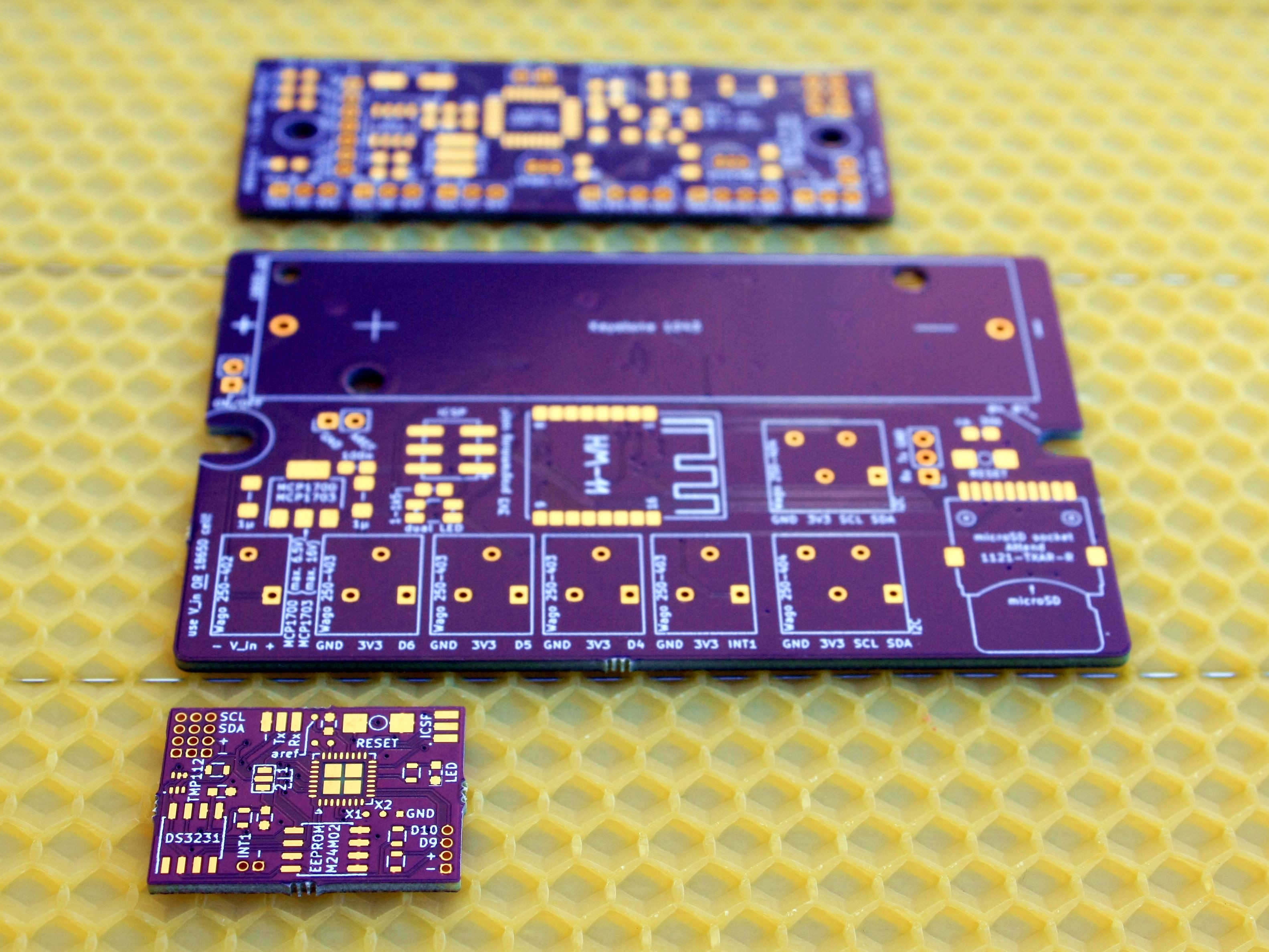
![]()
![]()
![]() ---------- more ----------
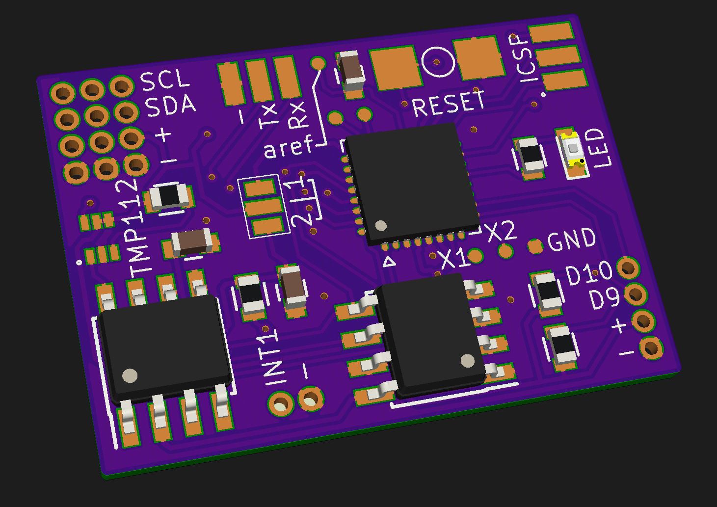
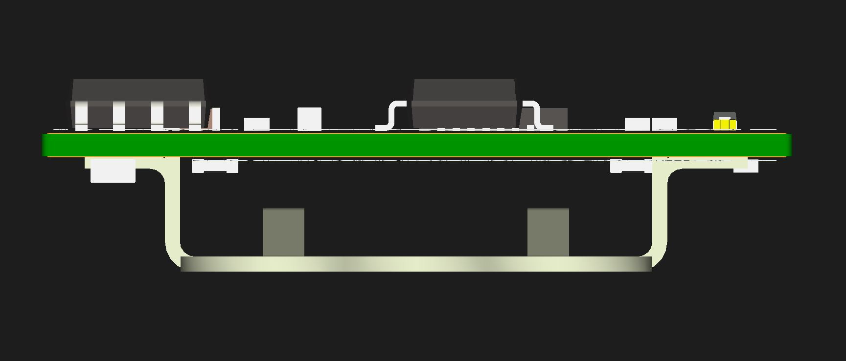
---------- more ----------Just a quick shot of the near-final board (nothing routed yet):
The wasted space on the right will be used for one or two additional digital pins, so one could use sensors other than I2C. I finally decided to use CR1632 button cells (switched between them an CR1225 a few times) to get around two years of use out of them. That's because the combs are used around two years and I wanted to shrink tube the circuit so I can't easily replace the battery "in the field".
Final size is: 25,3x18mm (1x0.71"). -
04 – logger and sensor position
08/12/2018 at 13:23 • 0 commentsUpdate 10.10.2018 - sensor glued into comb for test purposes
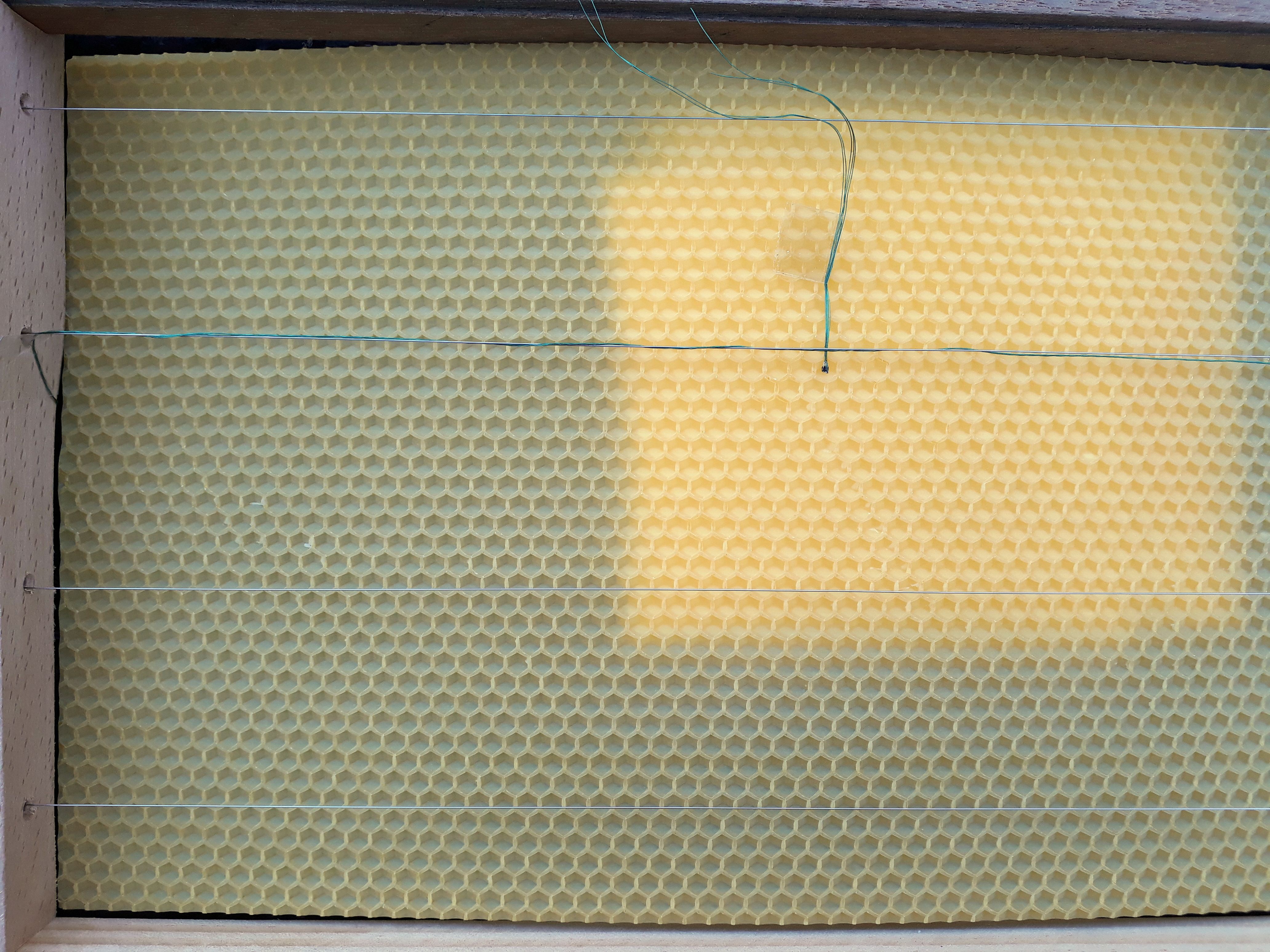
Today I tried "melting in" a sensor into a pre-formed comb / foundation. The 4-stranded copper wire is wrapped around the stainless steel wire with 3 turns, then the wax foundation is laid on top of it. Later, the stainless wire is heated by putting some amps through it and the foundation sinks in a bit. (Haven't done this step here).
What I have done is the wrapping part and aligning the test-sensor:
![]()
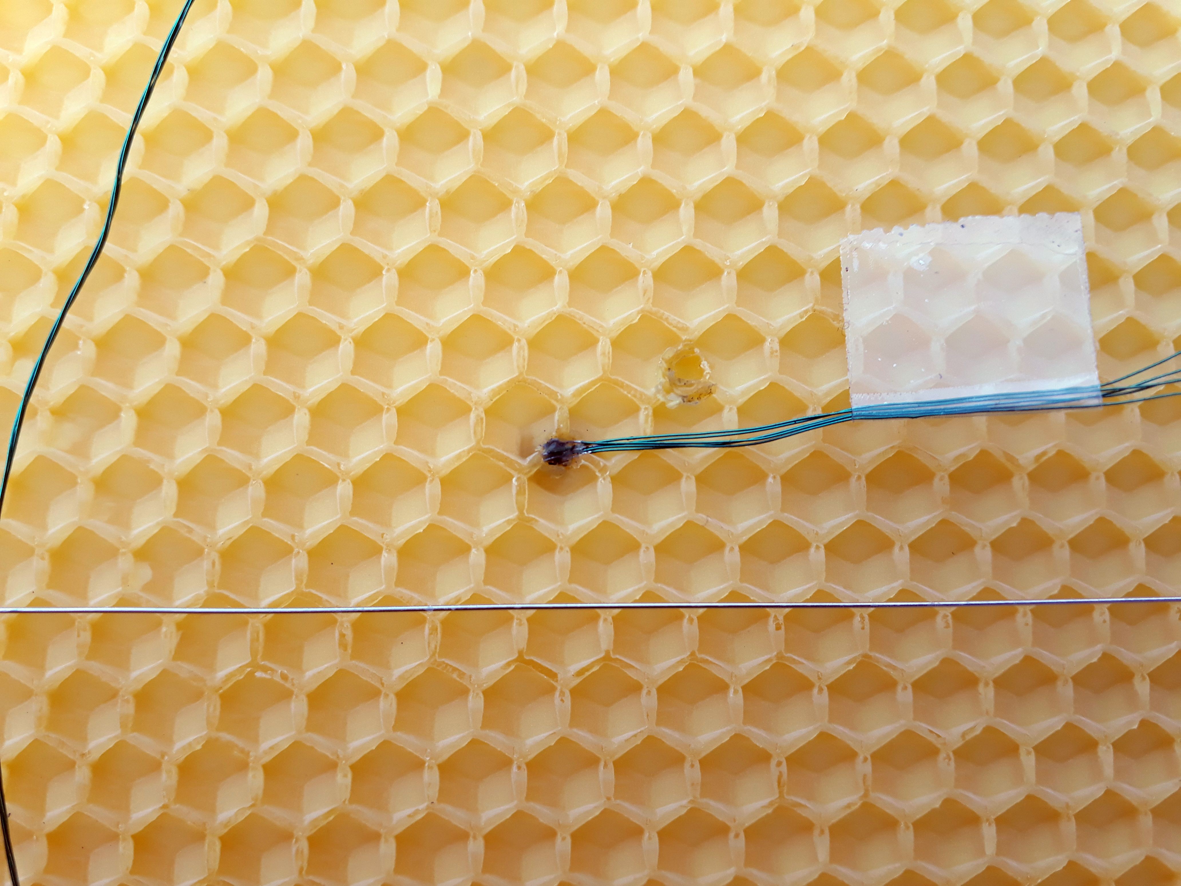
Then I heated a small metal rod and pressed it on the sensor so it melts into the wax foundation:
![]()
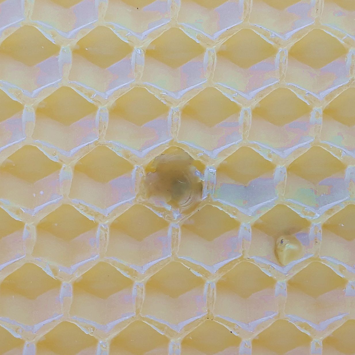
The other side looks like this:
![]()
I added a drop of molten wax so the bees won't abandon the cell because of a foreign body. Hope that'll do :)
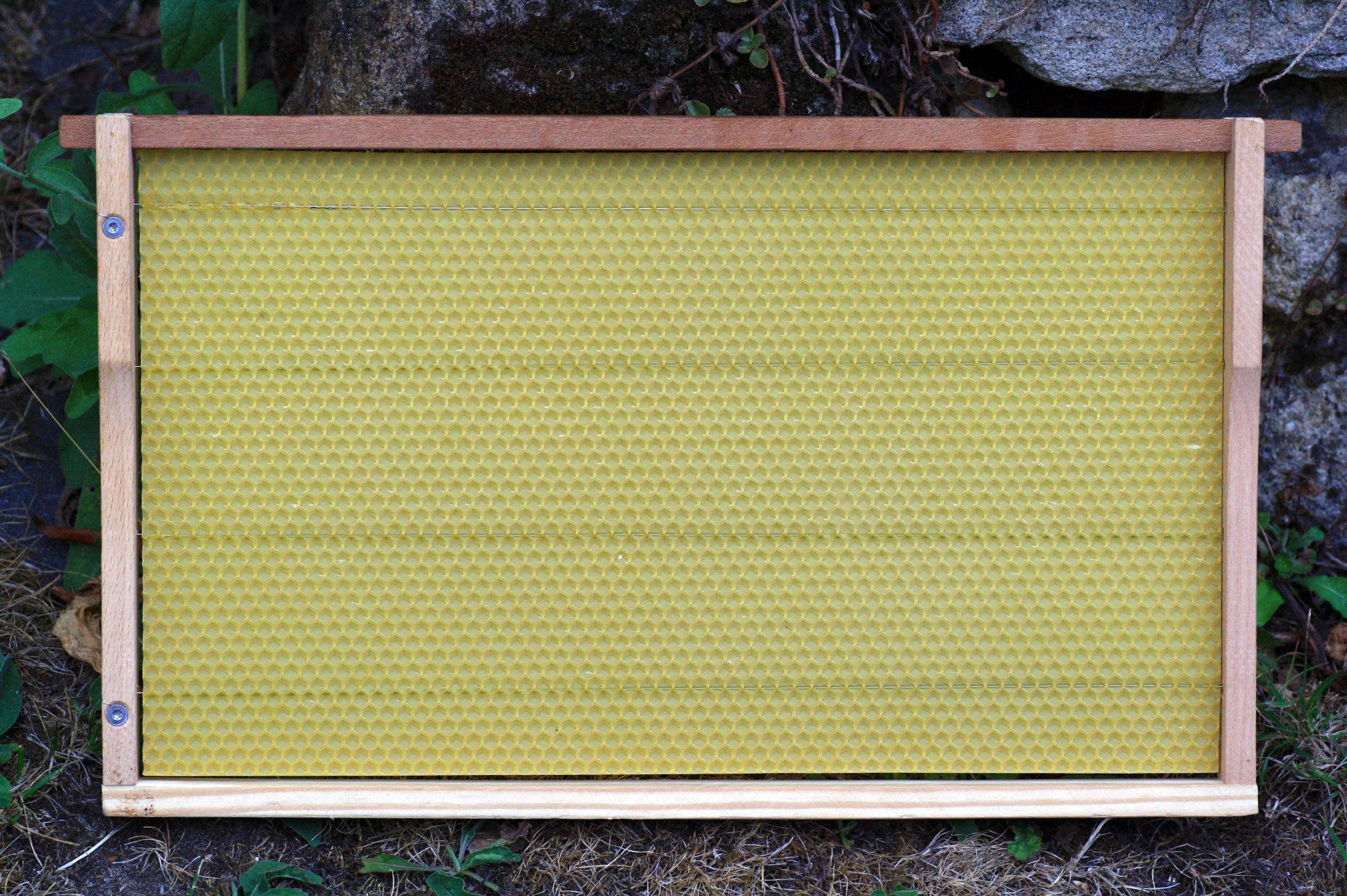
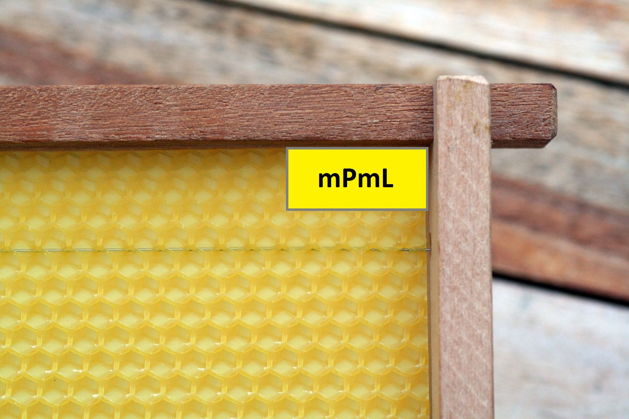
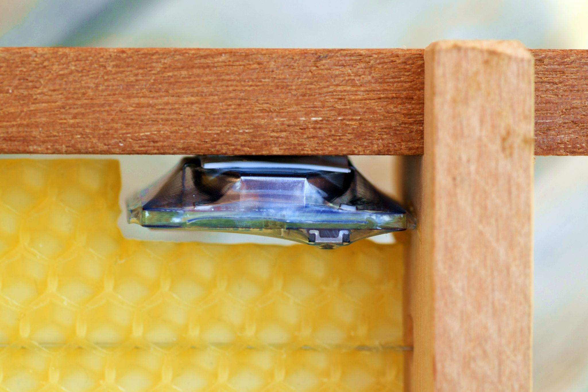
---------- more ----------The micrologger has that name for a reason :) It is so small, that it can be placed right in the frames which are put in the bee hives! Here you see a frame with a wax foundation:
![]()
wax foundation The top "bar" is 20mm wide, that's why I decided to shrink the logger to 25x20mm. I use very thin battery-pack heat shrink tubing to protect the circuit.
![]()
here goes the logger It will be glued in the space you see outlined.
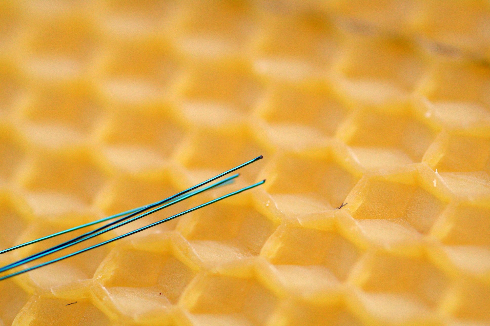
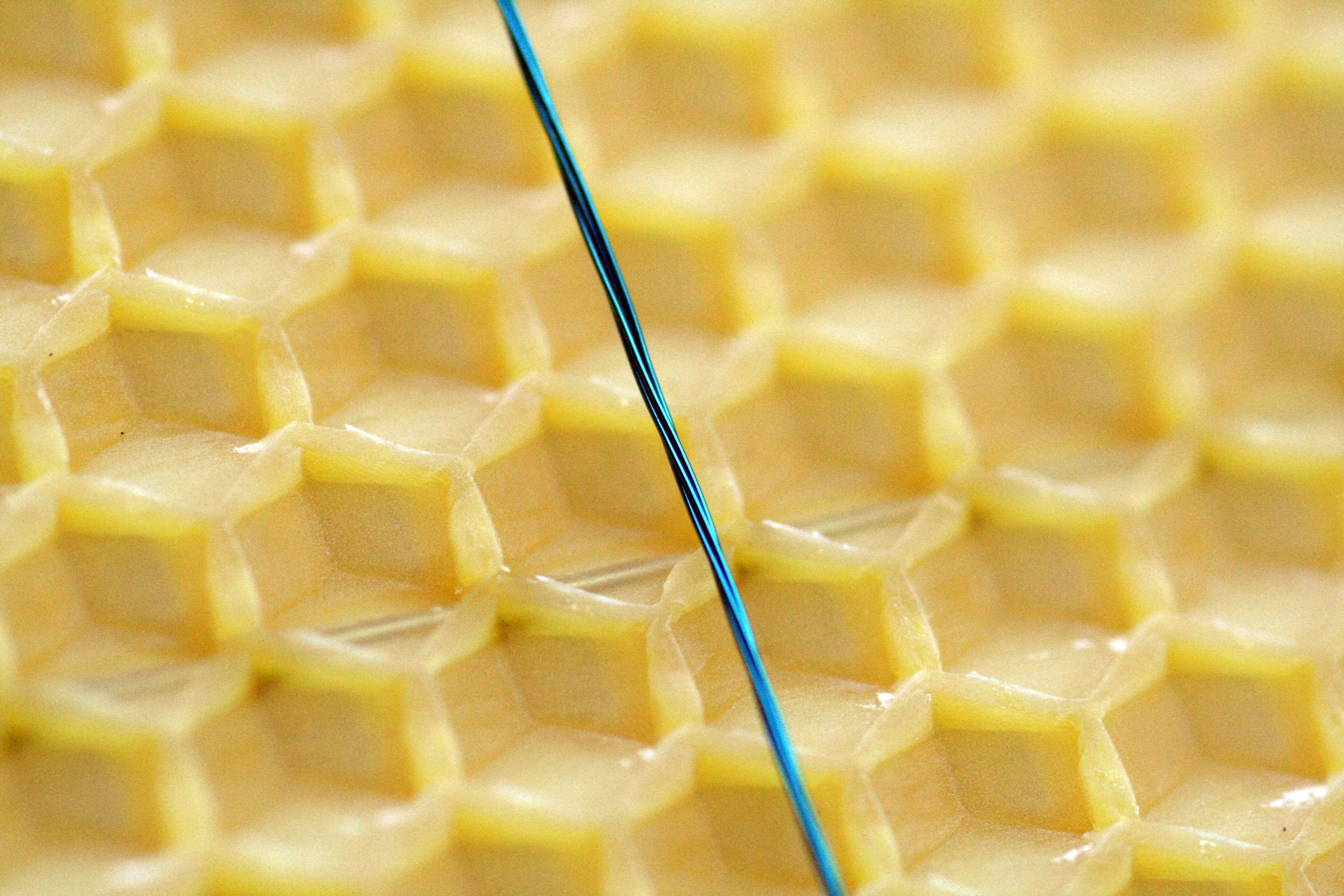
To not disturb the bees while building the cells, I can't use normal multi stranded wire to connect the sensors. So I chose enameled copper wire of 0.15mm diameter.
![]()
0.15mm enamelled copper wire 4 strands are first color coded and then twisted with a hand drill. The finished wire is 0.4mm in diameter, which can easily be routed on the pre-made wax foundation plates. It is quite durable, so you can bend it a few times without breaking the insulation.
![]()
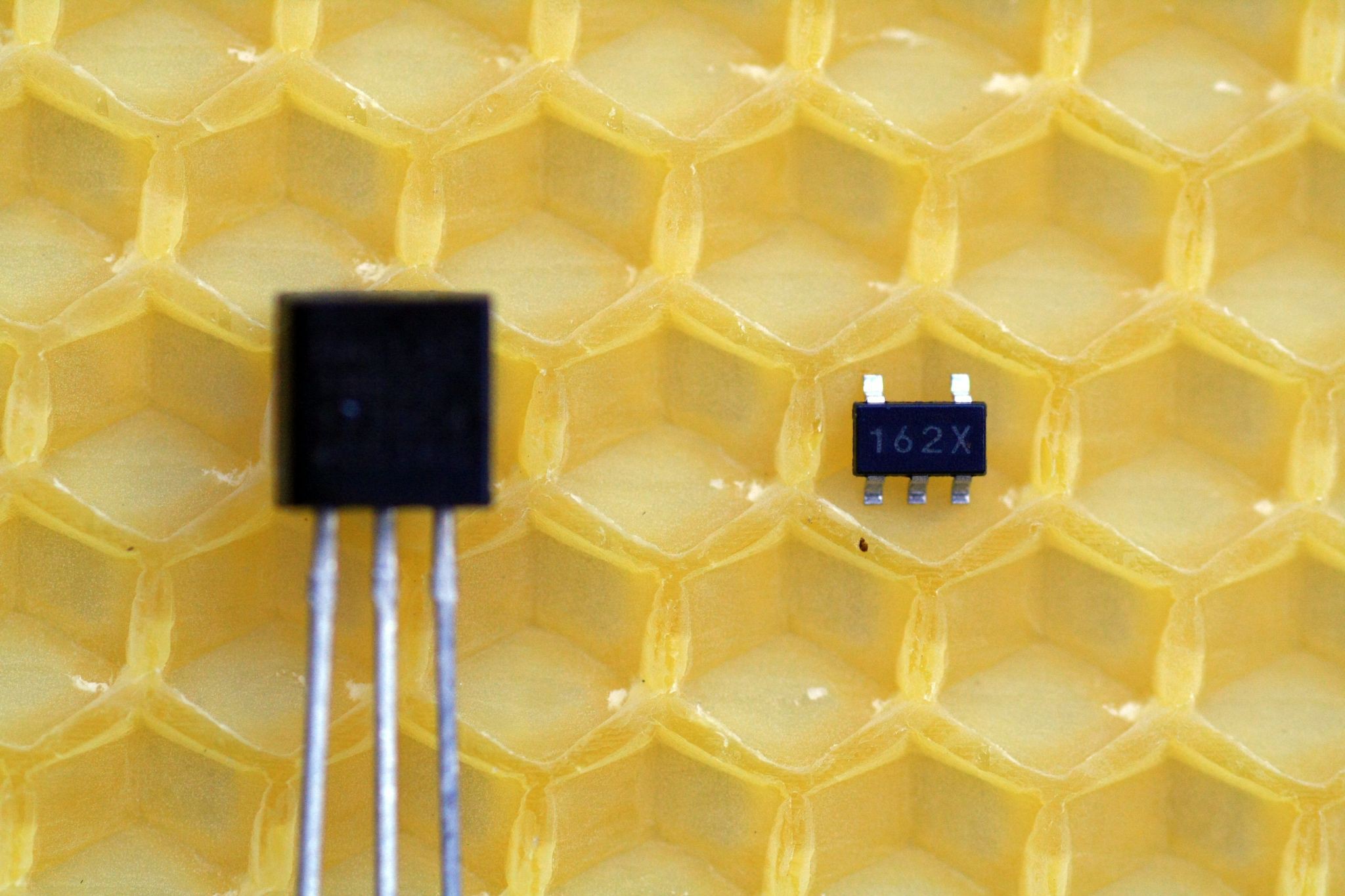
The next picture shows two different packages:
![]()
TO-92, left and SOT-23 next to it. I just ordered my TMP112 sensors which are even smaller than the SOT-23 package seen here. Will be quite the hassle soldering wires directly to it but let's see how/if it works.
I want to add it directly into the cell bottom!
micropower micrologger [mPmL]
A set-and-forget I2C/digital datalogger. Size: 25.3x 18x 10mm incl. battery. Runtime: > 1year
 Jan
Jan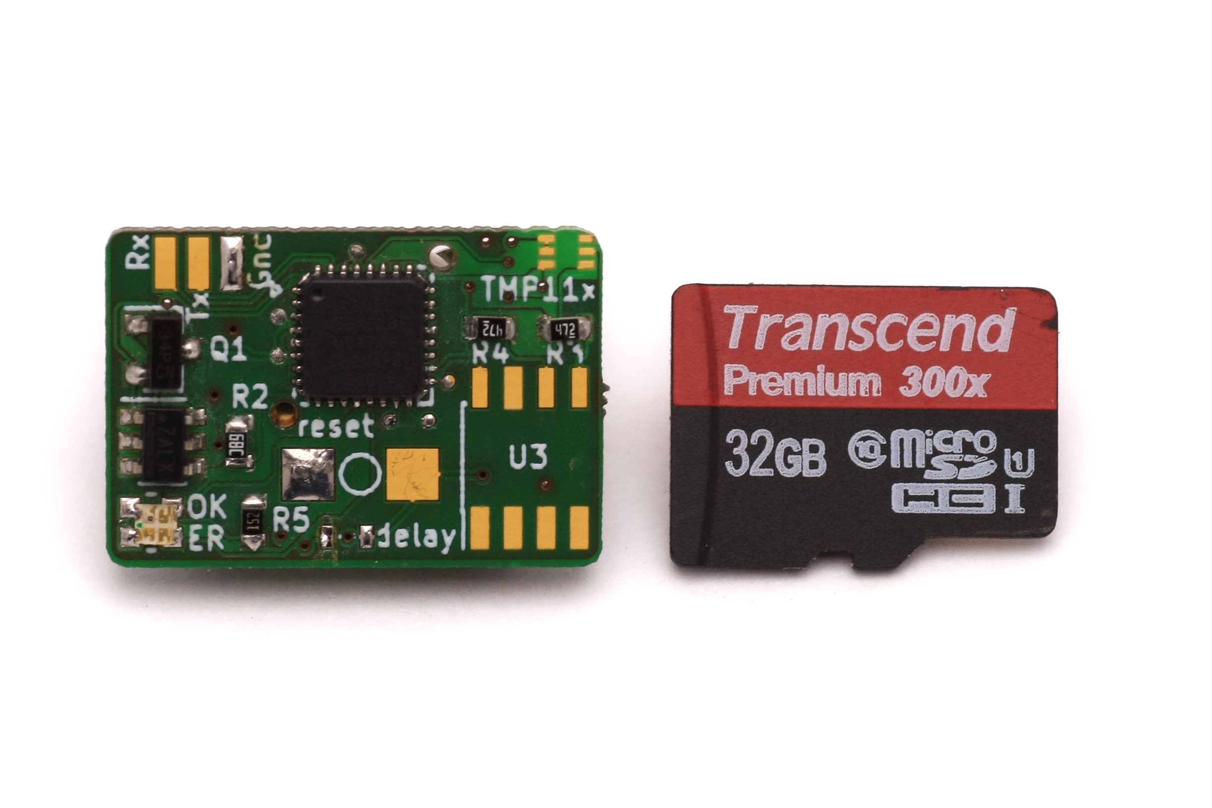
 HOW TO

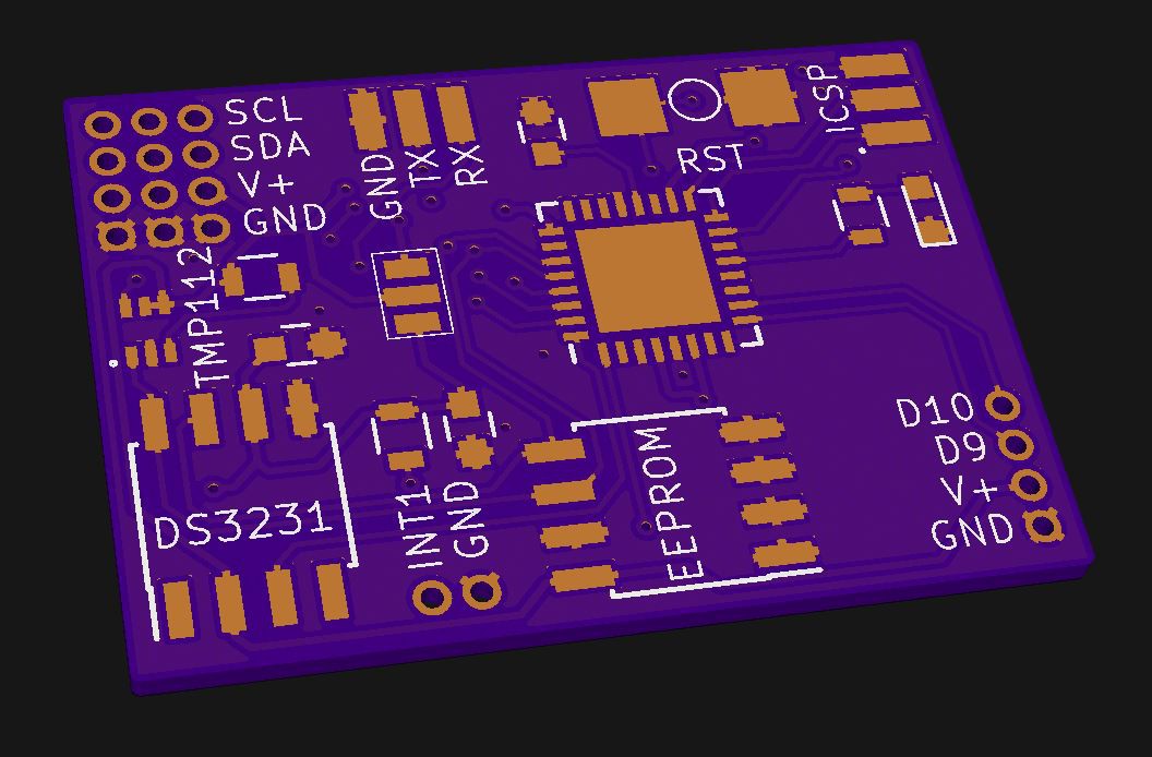

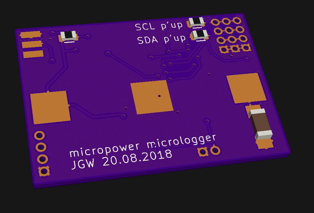
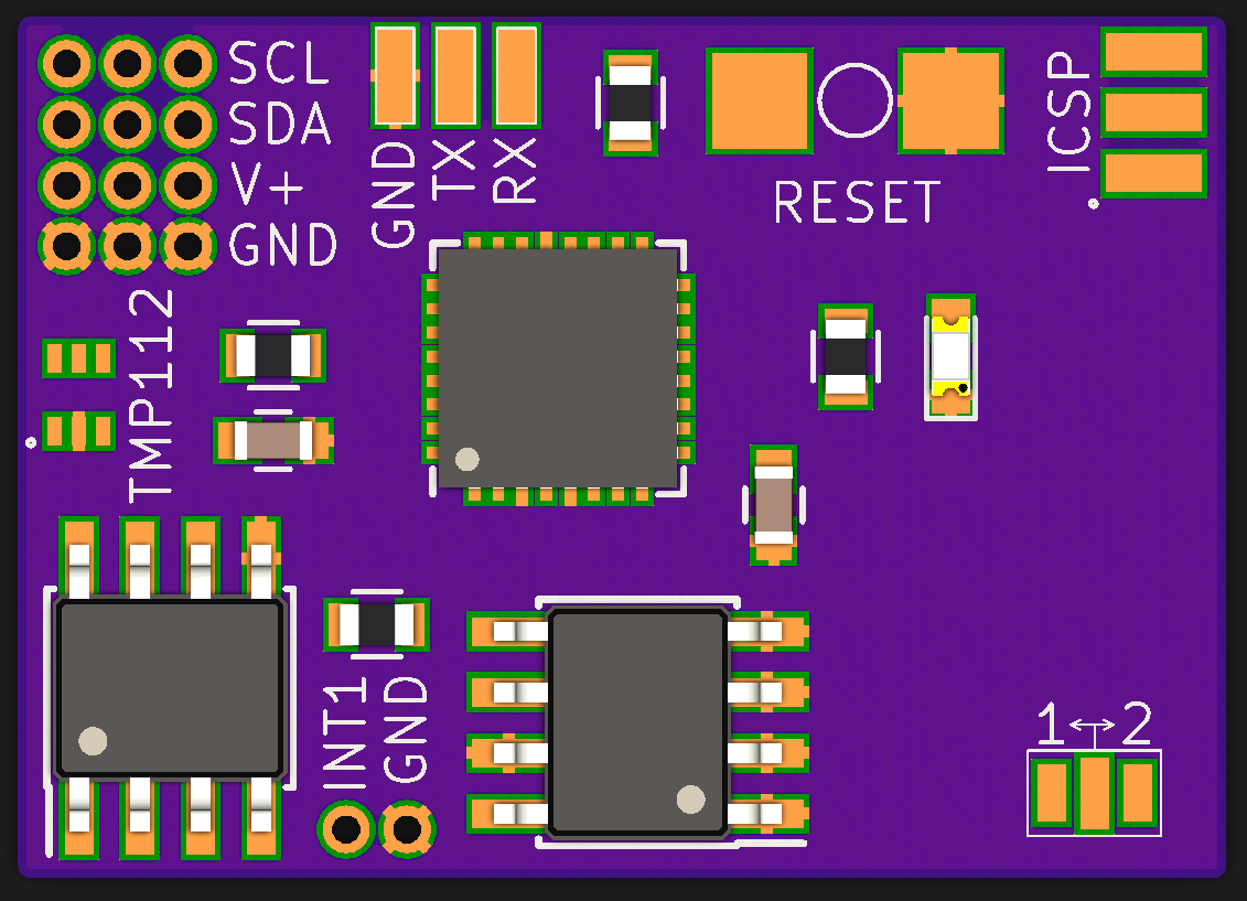 The wasted space on the right will be used for one or two additional digital pins, so one could use sensors other than I2C. I finally decided to use CR1632 button cells (switched between them an CR1225 a few times) to get around two years of use out of them. That's because the combs are used around two years and I wanted to shrink tube the circuit so I can't easily replace the battery "in the field".