-
1Making the PCB
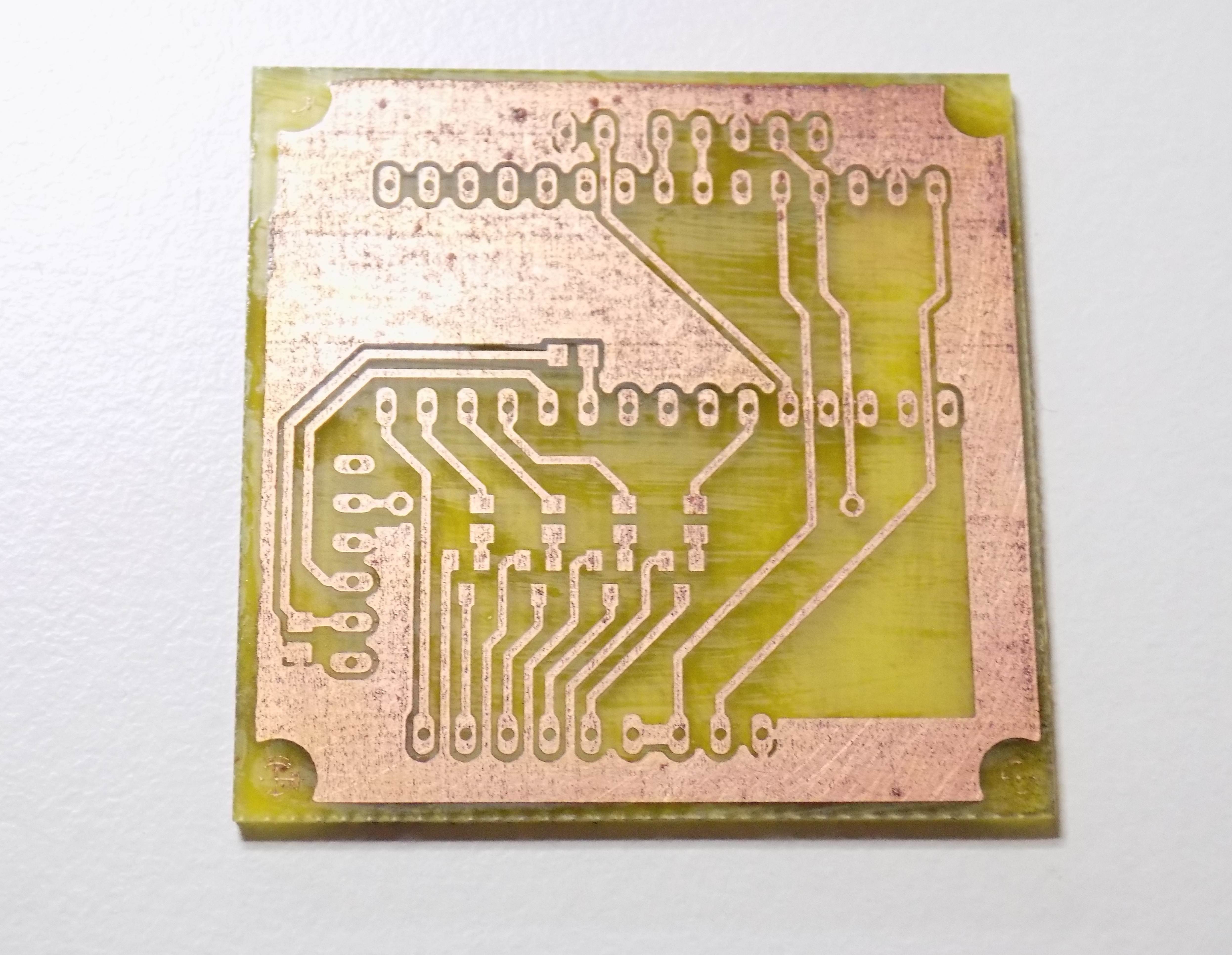
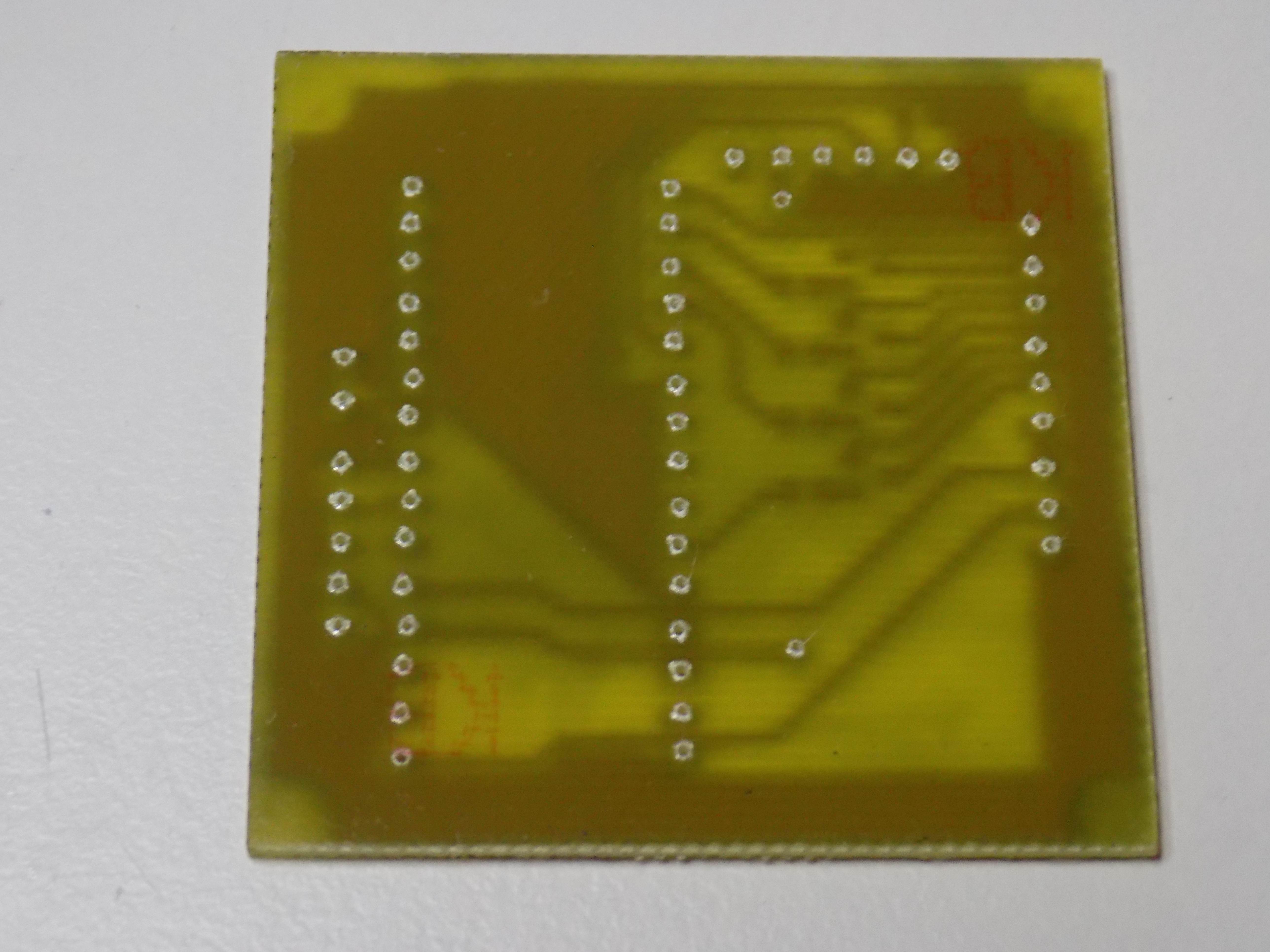
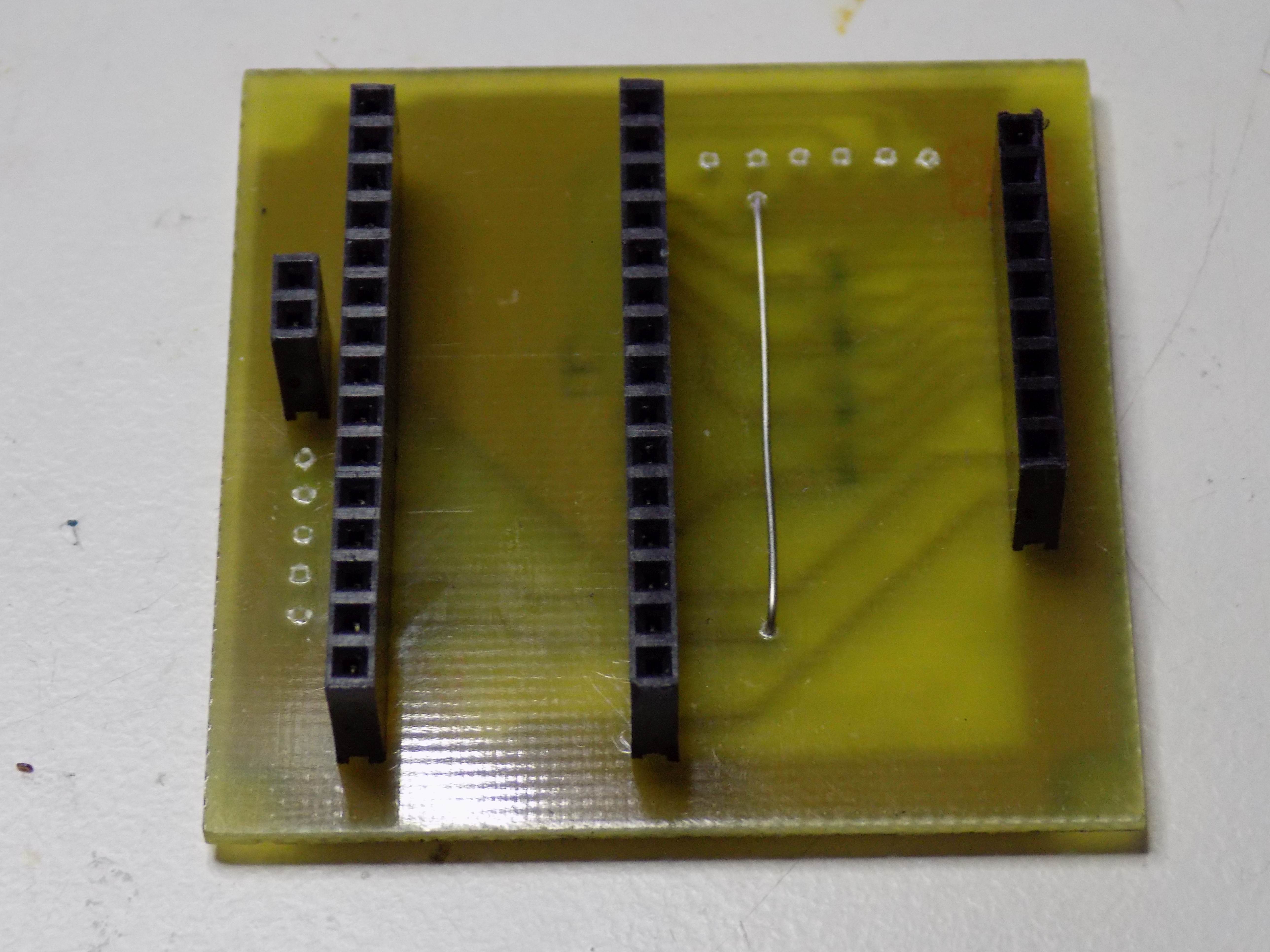
First step in making your own Ariadne Headband is to make PCB. You can get it made from professional manufacturer using Gerber files which are attached to our project site or since it is only single-sided board you can quite easily make it at home using toner transfer method as we have and shown in Log number two or any other PCB manufacturing method you are experienced with. All files necessary for making PCB at home are attached to project site. After you have done PCB start populating it firstly with SMD components then continue to the other side of the board and solder one wire jumper. After that solder pin header connectors. In the images below you can see etched, drilled and finally PCB mounted with components.
-
2Printing Parts and Placing Battery
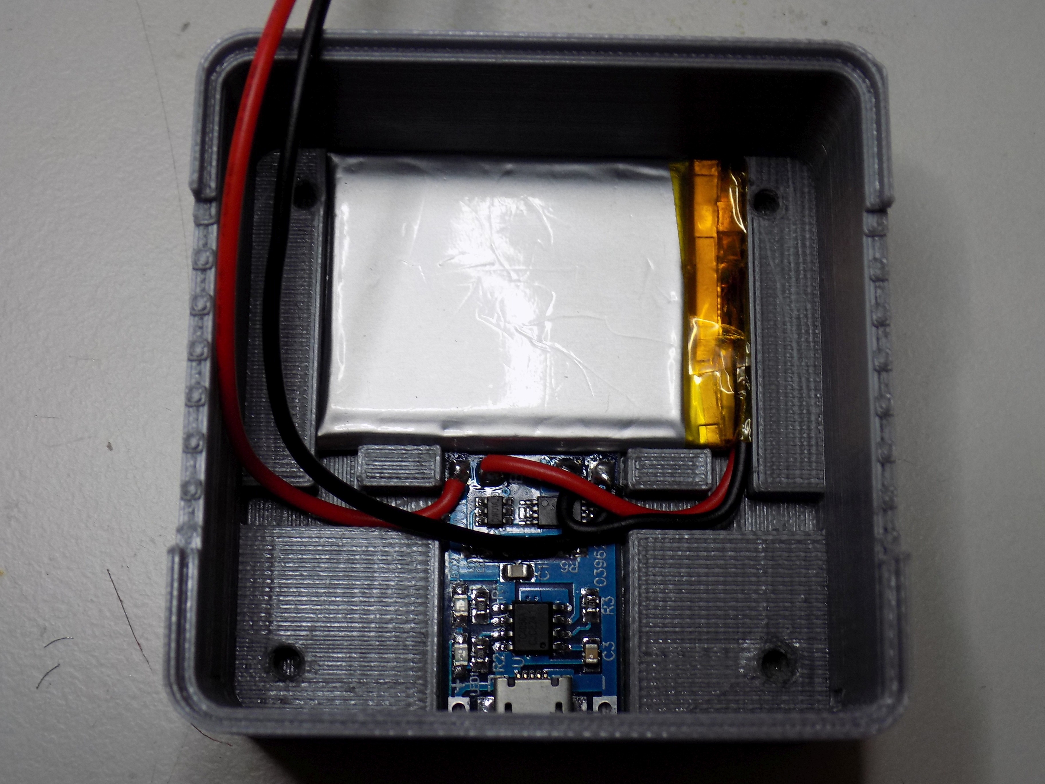
Next step is to 3D print all the parts for boxing for the electronics. You can find all the necessary STL files attached to this project. After printing box-bottom, box-top and box-spacer take 03962A Lithium battery charger module and superglue it to the bottom of box-bottom part such that micro-USB port will come through the cutout in the wall of the box. Then place lithium battery on the bottom and solder its wires to B+ and B- pads of the charging module as you can see in the image below. Since we have made upgrades to the Headband you have to make cut into the wall of the box for MOLEX connector and glue piece of velcro on box-top part.
-
3Wiring It Together
Next comes some wiring. Add sliding button into cutout above charging port and solder wire from charger module’s OUT+ pad to two of its terminals. To the last terminal of power switch solder two wires. One of them connect to IN+ terminal of MT3608 step-up converter and the second to pin header male connector as is shown in the schematic. From MT3608’s OUT+ terminal solder wire to pin header right next to the previous one. From OUT- terminal of battery charger module solder one wire to the pin header connected to GND of the PCB, second wire connect to MT3608’s IN- terminal. Solder two wires approximately 7cm long to tact switch and PCB terminals for it. Solder wires from piezo buzzer between arduino's pin number 5 and GND. Also solder 5 wires about 5cm long to MOLEX Mini-Fit 5569 5-pin connector and pin header.
-
4Checking Voltage
After everything is connected switch the button and power it, then check the voltage output from step-up converter module and by turning its potentiometer adjust output voltage to about 6,5V. Next press in right oriented arduino Nano and measure voltage on its VCC pin, it should be 5V. Then turn power off and connect to the PCB compass and bluetooth modules.
-
5Putting It All Together
Now its time to program arduino, you can find arduino program in our Gitlab repository which we have linked in our project site. Next connect headband and power pin header connector, pay attention to right orientation and switch the power button. While starting you should hear simple melody, after pressing tact button some motors should start vibrate.
It should be motor in direction of north, if not you have to switch output pins for motors in arduino code until its right. Next you should try to connect to the Headband with your phone. If everything works place 3D printed box-spacer part on the top of battery, then PCB on top of it. Next screw standoffs through PCB into the boxing make sure everything is in order and then place box-top part on it and screw M3x15mm screws into standoffs. Before closing box it should looks like in the image below.
-
6Making the Rubber Headband
Now, you need to create a wearable "device" where you put the vibration motors. You can use a hat for example, but for our case, we will stay with classic sport headband.
For the rubber headband, you will need to buy one that is either 6 cm wide (so you can fold it) or double the length of 3 cm wide rubber. Then, measure perimeter of your head and and cut the rubber. Add approx. 2 cm so you can easily connect each sides together and sew them.
Now, put the headband on your head and mark places where will the motors be placed. They should be placed at 45, 135, 225 and 315 degrees (0 degrees is between you eyes). If you have 6 cm wide rubber, you will fold it in half and sew the open end. Because of this, place the vibration motors in the middle of the rubber's half that will be closer to your head. You can sew both sides together to form some form of capsule to keep the motors in their place.
Next, make sure the cables are long enough because you will often stretch the rubber and you do not want them to tear. Make a small hole about 5 cm right off the center on the rear side of headband. Pull the cables through and put them into the connector.
Then, put all cables inside the rubber and sew the open side of the headband. I recommend to use some sort of "snake" style sewing to make it more flexible.
When you have everything finished, the last thing you need to do is to connect about 5 cm long piece of velcro exactly in the center of headband rear side (where you have the connector). Glue the second part of velcro to case with electronics.
You can find pictures in one of our logs.
And that is all for the hardware part! Power the Headband, connect your phone and you are ready.
Ariadne Headband
Arduino-based heaband that uses haptic feedback to navigate blind people. Controlled via Bluetooth using Android app.
 Vojtech Pavlovsky


Discussions
Become a Hackaday.io Member
Create an account to leave a comment. Already have an account? Log In.