Once we finished testing our circuit in breadboard it was time to make it more solid. We considered few options how to connect modules and other components together, namely connecting modules with wires and leave them sort of loose in the box but because there are other components than just modules it wasn’t suitable solution. Another option was to solder everything onto a universal PCB, this would be better and quite easy to make but we planned to use SMD components to save some space and also it would be harder for us to document it properly and for other people to rebuild it, therefore we’ve chosen slightly more difficult approach to make custom single sided 50x50mm PCB which you can see in photo below.

By far easiest and fastest way to make reasonably good quality PCB at home was using toner transfer method. After ironing toner onto copper we etched it in ferric chloride, drilled holes and soldered all the components. Bottom side of the PCB doesn’t look so pretty because some toner left stuck to it. In the project files you can find image of the PCB in 600DPI and placement of components.
Power management
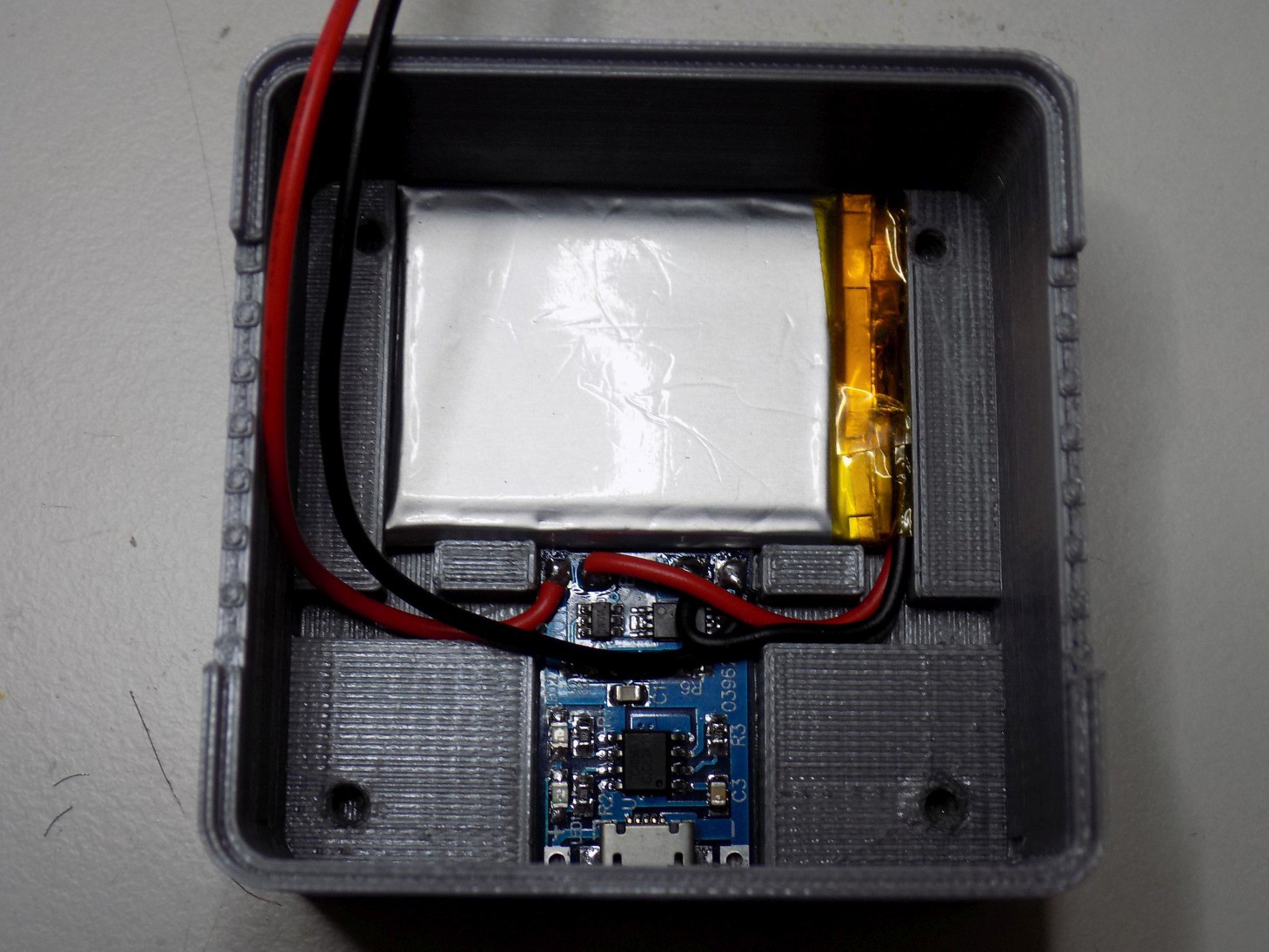
For Headband to be a wireless device as it is, it needs some way to store energy. For this purpose we’ve picked a LiPo battery with dimensions 4x30x40mm and 550mAh capacity. Together with 03962A charger module it lies on the bottom of the box. Charger module takes care not only of charging the battery but also protects it from overdischarge by disconnecting it from the circuit when battery voltage drops under 2.5V and shortcircuit by sensing overcurrent. There is also a micro USB connector on the board of the charging module which serves as easy way to charge the Headband.
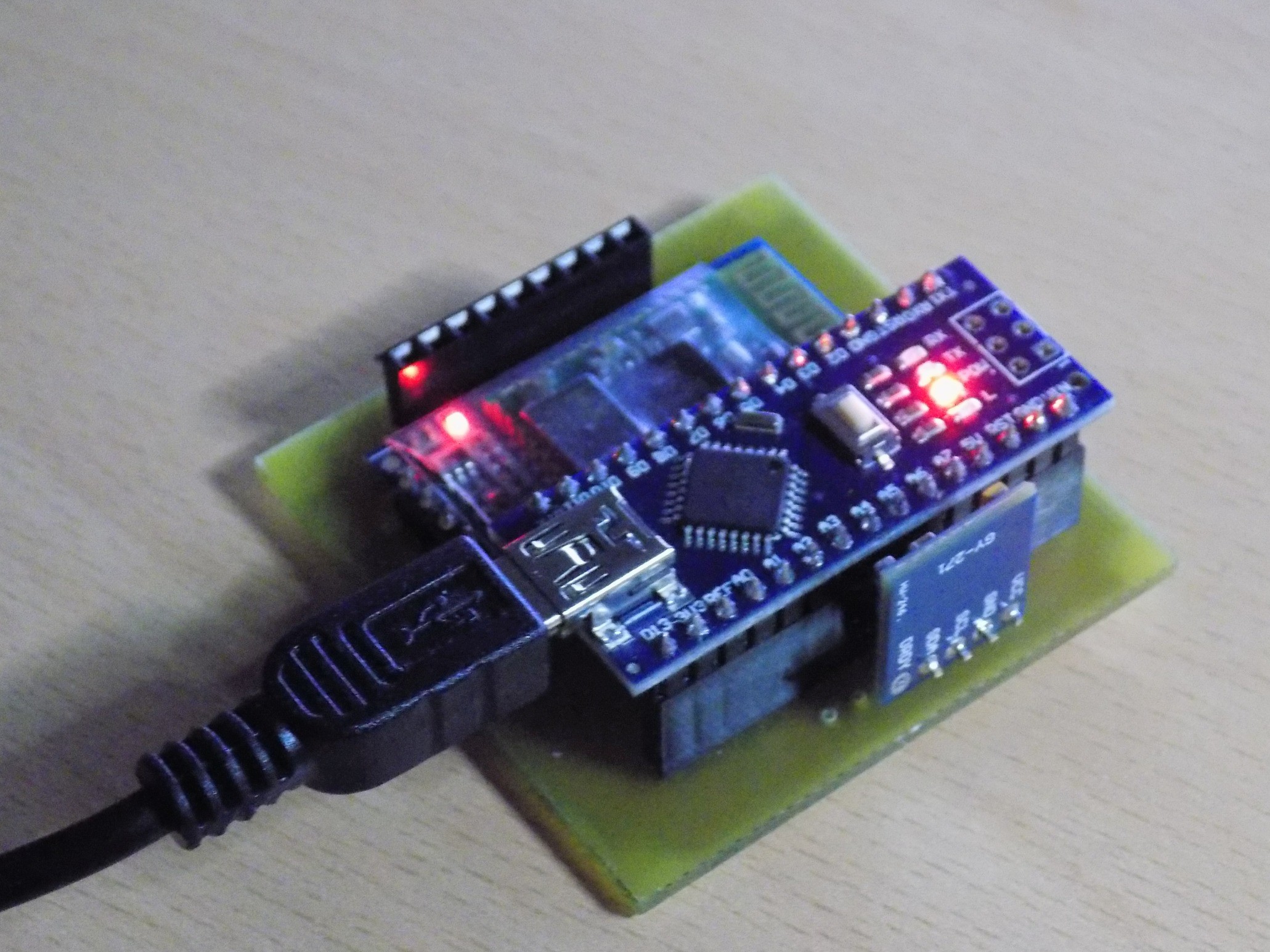
Initially we planned to have electronics in Headband running on 3.3V but when we got all modules together it got more complicated. Arduino Nano board is supposed to be running on 5V and it has its own 5V voltage regulator, on the other hand both HC-06 and GY-271 modules use 3.3V and they are also equipped with onboard voltage regulators. We faced dilemma of either run everything on 3.3V and hope that arduino will keep working properly or somehow get 5V supply. We’ve chosen to play it safe and use MT3608 step-up boost converter to increase voltage from battery one to approximately 6.5V and then run it through Arduino’s voltage regulator to get stable 5V supply. However in future we want to use only 3.3V, it would be possible to use for example Arduino Pro Mini which is intended for this voltage and LDO voltage regulator connected directly to battery.

Box
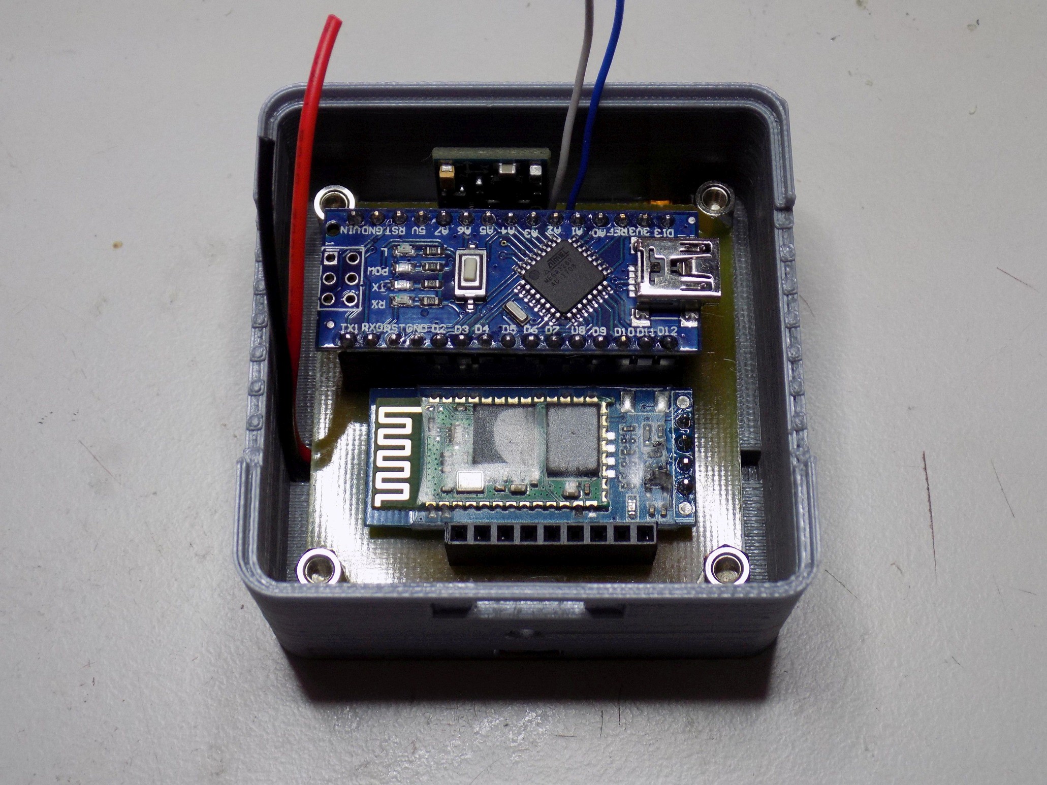
Box for the electronics has dimensions of 60x60x30mm, it was 3D printed and consists of three parts: bottom, top and spacer, all STL files are uploaded on this project. Basically bottom part contains everything and top serves as lid. Between these two parts are two gabs where rubber comes through into the box. Top part is firmly held in place by four M3x15mm screws, this and small teeth in gabs ensures that rubber won’t fall out. Between battery and the PCB is placed thin 3D printed sheet which acts as spacer and ensures that sharp leads on the bottom side of the PCB would not damage the battery. PCB is fixed into the box with four standoffs in its corners into which comes screws.
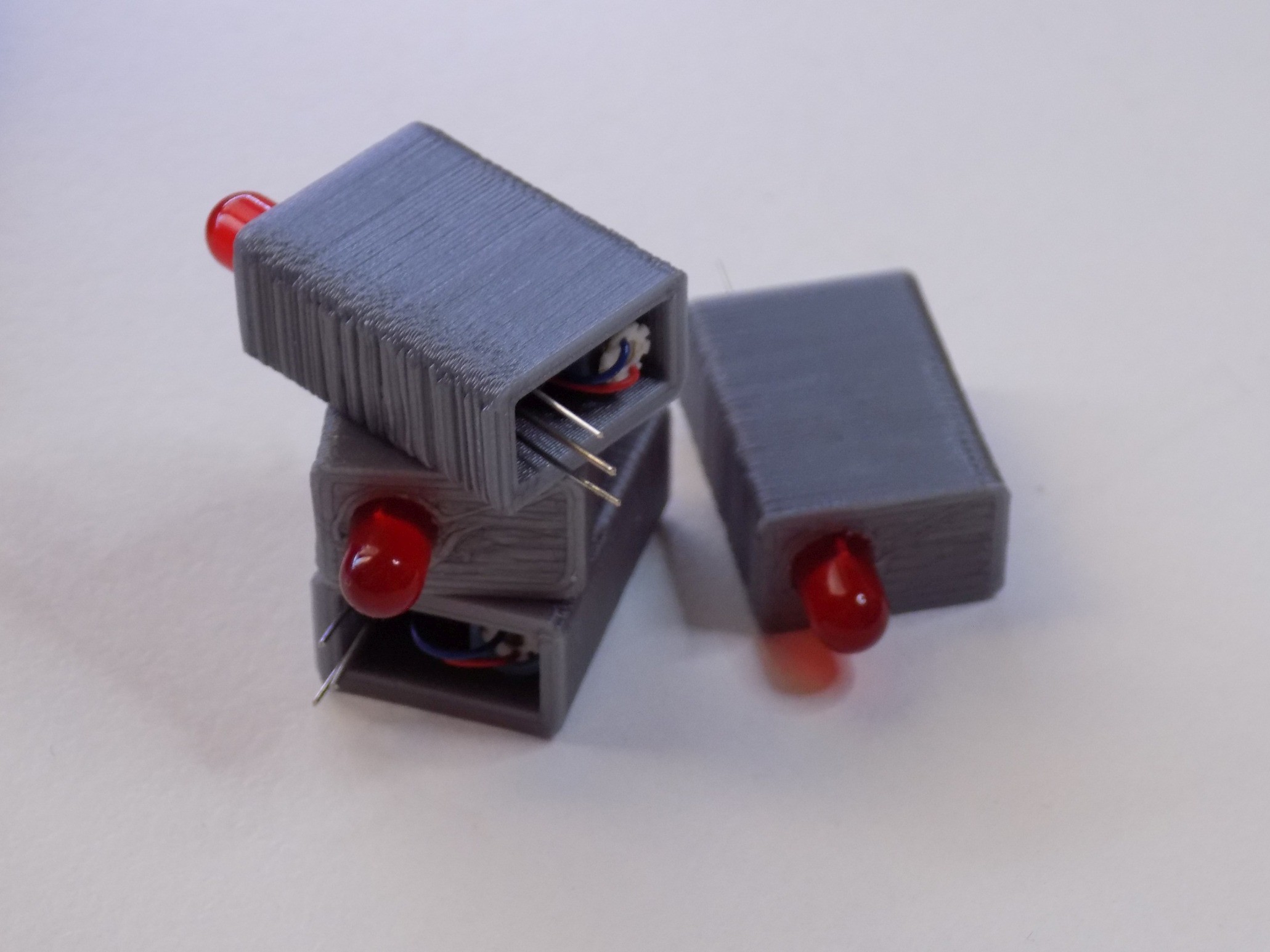
Box with electronics is only one part of the Headband. The other part is rubber band which comes around your head and in which vibration motors are held. Rubber band is 50cm long and 60mm wide, it is folded in half and inside are placed motors and wires connecting them. Each motor is placed inside 3D printed housing together with LED, its resistor and a diode. We bought vibration motors in local store and in future we may switch to flat ones and omit the whole housing. The only purpose of LEDs is to show in photo or video which motor is currently active and in future we will probably get rid of them.
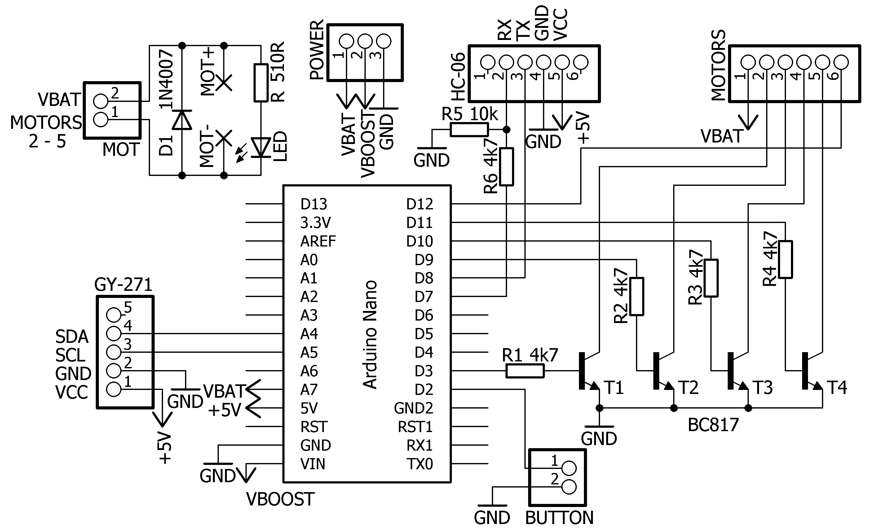
Vibration motors can’t be driven directly from Arduino’s outputs because at 4 volts each of them draws almost 100mA which is way more than Arduino can handle. So we added four bipolar NPN transistors each for driving one motor. Headband is now working just fine, it has some hardware features which we did not yet addressed in software such as switch button and measuring of battery voltage. You can see whole schematic of the headband in the image below.
Discussions
Become a Hackaday.io Member
Create an account to leave a comment. Already have an account? Log In.