 Jasper Sikken
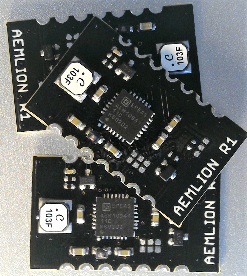
I have soldered the components onto 3 boards using a solder paste stencil and a hot air gun.
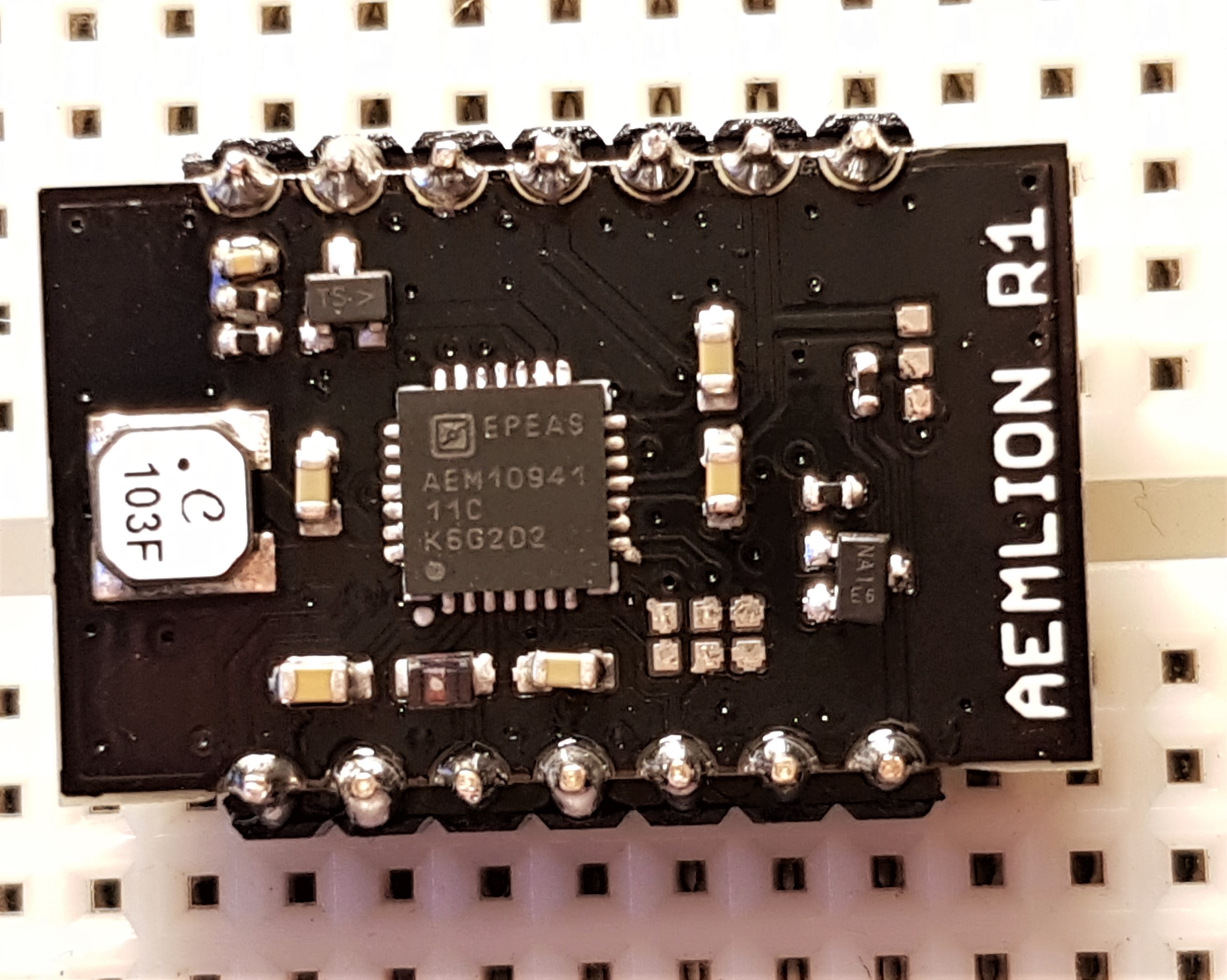
They also solder well on to 0.1" header pins for use in a breadboard.
Then hardware verification could start.
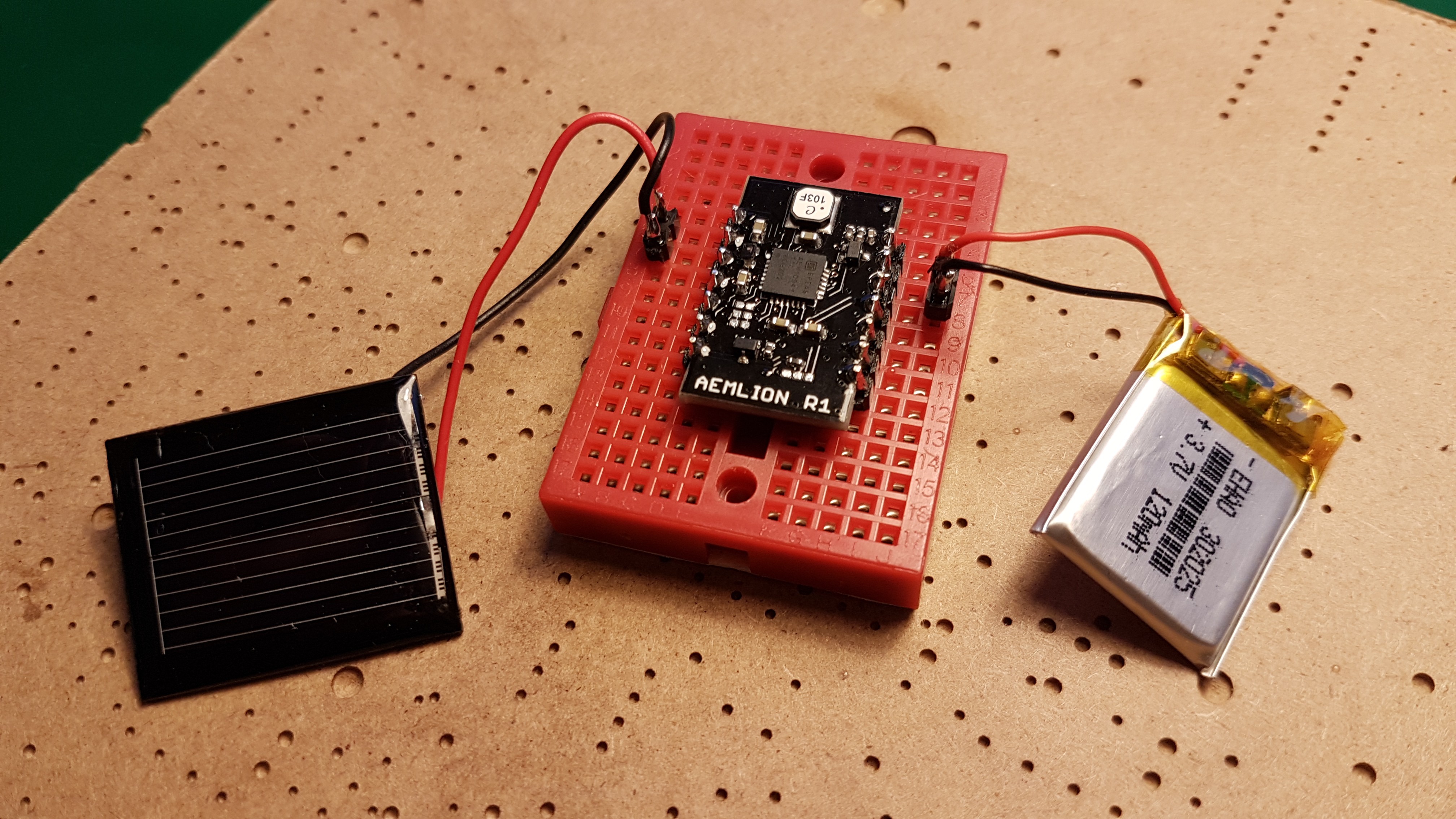
I connected a 20x25mm Li-Ion battery and 1V/100mA 30x25mm solar panel. I measured the 1.8V and 3.3V on the outputs. which only happens when the circuit is able to charge. The solar panel voltage was close to the expected 75% of the open circuit voltage. The battery voltage divider with 4.7M and 10M resistors worked as expected. As well as the mosfet with the status output pin.
Discussions
Become a Hackaday.io Member
Create an account to leave a comment. Already have an account? Log In.