 roger_archibald
The firmware doesn't have a whole lot to do: when power is applied, the micro pulls a variable out of a location in EEPROM and runs a switch/case on the value of that variable. The switch case will run one of out of several different light shows, depending on the value of the variable. After the light show, the variable is incremented and saved back to EEPROM, and the micro goes into deep sleep. The button on the board is actually the micro's reset line. Pressing it will reset the micro, where it will start the sequence over again.
Different sequences take advantage of different Timers/PWM functionality.
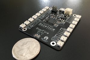
With only 40 solder-joints total, this is a relatively un-intimidating introduction to SMT soldering. There's enough stuff that it will be challenging for those new to SMT, but simple enough that a skilled solderer can replace/fix any errors quickly to keep a class moving.
 maehem
 Sander van de Bor
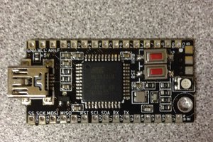
 The Big One
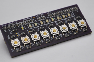
 Charlie