Ellie T
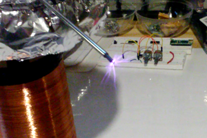
An electromagnetic terrain conductivity device can be used to determine the ground conductivity and thus content. The transmitting (primary) coil generates an oscillating magnetic field which induces eddy currents in the ground. These eddy currents then reduce the magnetic field at the pickup (secondary) coil, and the percent reduction of magnetic field can reveal conductivity of the ground.
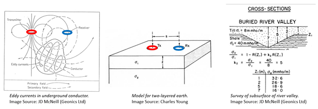
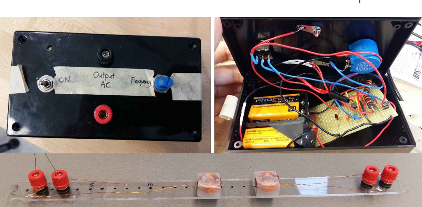
Terrain survey is useful for sourcing water, prospecting minerals or oil, and construction. However, an AC source is required to power the meter and AC sources are not easily available in the field. Conventional DC to AC inverters are powered by bulky 12V batteries with lots of wires and have a fixed frequency of 60 Hz. Thus the goal is to create a highly portable AC generator with variable frequency that can power the primary coil to induce a readable signal on the secondary coil.
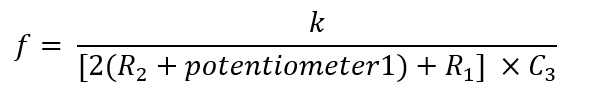
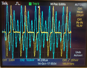
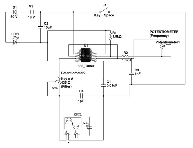
 The blue curve on top shows the voltage across the secondary (receiver) coil with lots of higher frequency oscillations. The blue curve on the bottom shows a nice sine wave with the higher frequencies filtered out. Based on the RC equation below a 1pF capacitor was needed for a frequency of around 192 kHz.
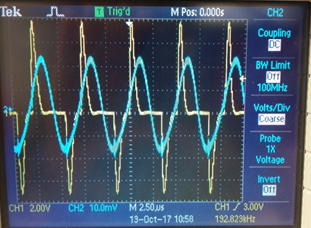
 Sebastian
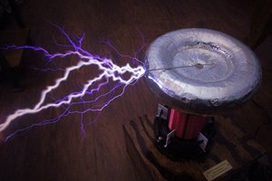
 Zach Armstrong
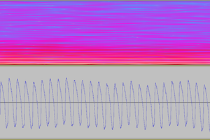
 Marek Materzok