 Ellie T
Since this unit is to be used for field work, it needs to be portable (battery powered). The parts should be cheap and easily available. For a big enough reading induced on the pickup coil (Vpp > 10 mV), a big enough voltage supplied to primary coil is needed to drive and pull enough current through the primary coil. Lastly, the unit must be able to vary oscillating high frequencies (1 kHz – 1000 kHz) to suit other factors such as terrain conductivity , and coil spacing.
I considered a transistor, op amp, and 555 timer oscillator circuit. The specific transistors required for an oscillating circuit were not immediately available, and the frequency is not as easily changeable, so I did not pick the transistor circuit. The Op-amp (LM741CN) did not work well with high frequencies, which was observed on the breadboard prototype and verified in the datasheet. Furthermore it needed more than two 9V batteries which would make the system more bulky.
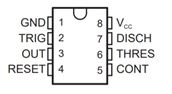
Thus I chose the NE555P timer which would run in astable mode, as it can generate a very high frequency which is easily controllable by pin 5.
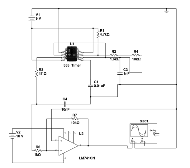
The unknown inductance of the coils must be very large, as there was severe kickback to the circuit. Adding the Op-Amp protected the 555 oscillator (retaining square wave) and provided a gain of ~1.75, but the LM741CN could not power up with two 9V batteries, and could not drive sufficient current through the coil (worse than without the op amp). Since the cons outweigh the pros, I removed the op-amp and increased the input to 555 to 19V so that output is higher (previously Vpp ~ 5V).
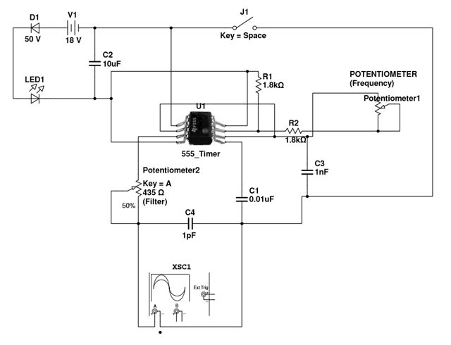
Since the NE555P max input voltage is 16V according to the datasheet, I used a diode and LED to reduce the input voltage.
Discussions
Become a Hackaday.io Member
Create an account to leave a comment. Already have an account? Log In.