Close
0%
0%

DIY Wastewater Treatment Controller

Project goal is to build a controller for home wastewater treatment plant.

Similar projects worth following
Majority of home sewage treatment systems have no controllers but there are benefits of having it such system. Most of all it reduces energy consumption of treatment plan. It extends air pump lifetime. It also allows to reduce capacity of water tanks in sewage system. By reducing capacity of water tanks it allows to install wastewater treatment system in smaller area. It simplifies maintenance procedures of sewage treatment plant. As addition controller might monitor state of key elements of the system.

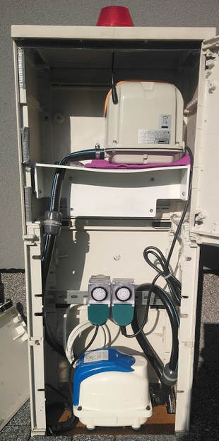
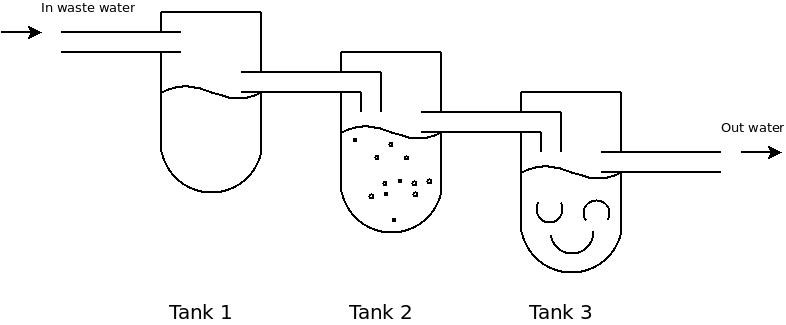
There are multiple approaches for sewage treatment. In general multiple stages of water treatment exist. Usual principle is that on every stage we have our waste cleaner compared to previous step.  In simplest installations wastewater treatment consist of three water tanks. Where I live three tanks system is the most popular wastewater treatment concept. Controller that is built as part of this project directly fits to such a system but it also can be adopted to other wastewater systems. Project doesn't provide details on how to build sewage treatment plant but focuses on controller only.


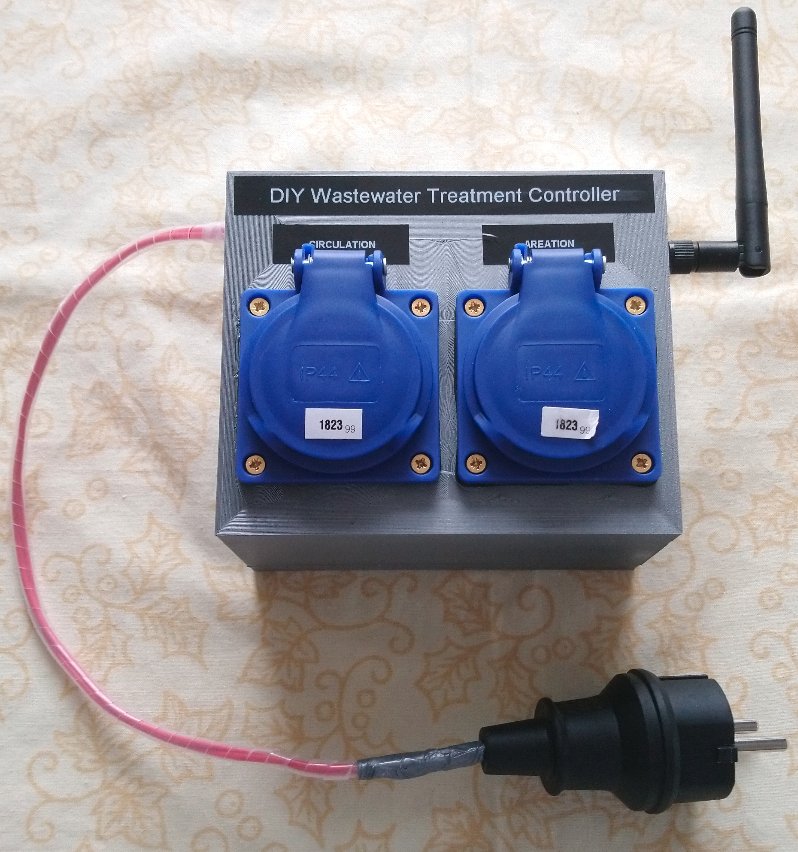
Controller is an entity that allows to:

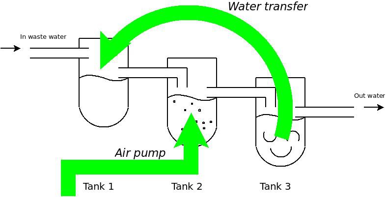
  • Reduce power consumption for wastewater treatment process by powering on and off the air pump
  • Reduce size of wastewater treatment plant by creating circulation flows between water tanks
  • Simplify maintenance procedures as in long term there is only one tank that require waste water drain
  • Remind to execute maintenance procedures for sewage treatment plant
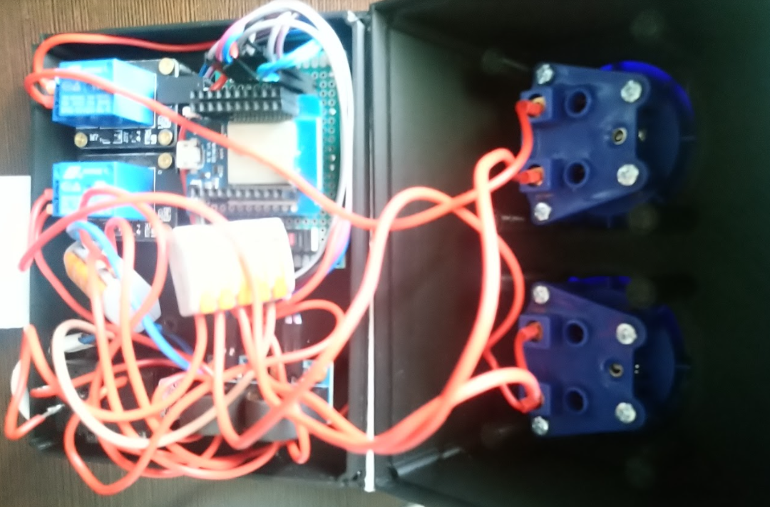
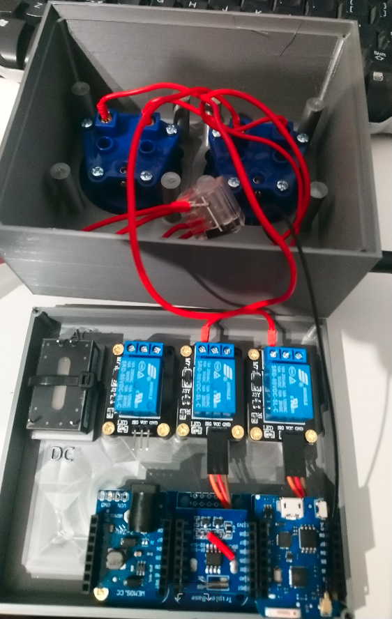
  • Monitor execution elements of sewage treatment elements

Project consist of two parts:

  1. Reverse engineering of commercial off the shelf controller
  2. Building controller from scratch

For anyone that is interested in wastewater treatment process I provided brief explanation in one of my first logs. I encourage you to expand all logs in this project. In case of any question please feel to ask in comment section. 

saturdayHackHoliday.ods

This is raw data for controller settings discovery. Data is collected using Arduino as described in project log. Spreadsheet captures data for holidays MonoBLOC operational mode.

spreadsheet - 34.43 kB - 08/22/2018 at 05:03

Download

saturdayHack4nominal.ods

This is raw data for controller settings discovery. Data is collected using Arduino as described in project log. Spreadsheet captures data for nominal MonoBLOC operational mode.

spreadsheet - 36.70 kB - 08/17/2018 at 19:02

Download

  • Controller V4

    leszek-wojcik08/24/2021 at 21:39 0 comments

    Its been a long time but finally I was able to work a bit on controller and I managed to add some features.

    - Firstly I moved entirely from ESP8266 to ESP32

    - I've added WPS push button into board and programed it. It allows to configure WiFi network

    - I've added circuit that allows to me read AC current flow in each socket, so that air pump is constantly monitored.

    - ESP32 allowed me to connect controller to cloud using secure TLS/MQTT

    - MQTT statuses are regularly sent to cloud.

    - I'm able to reconfigure controller settings using IoT thing shadow service

    - I also prepared some draft android app for manual control and monitor but I'm not pursuing this further.

    Remaining development task is to be made at cloud. I need to create a rule that will send me an e-mail when pump failure is detected. It would be great to create custom PCB as well.

    When one of my air pumps will broke then I will redesign enclosure so that I can hookup AC valve coil instead of auxiliary pump. This will enable me to reach a point where only single air pump is needed for solution. For now dual pump design works good for me.


    Controller sits in place and do what was created for. Since all major project goals are met I decided to mark this project as completed... and now pursuing some other challenges.  Project was fun to work. It might seems that waste treatment is unpleasant topic but this project was indeed satisfying and provided me with framework experience that I will use in my next projects.

  • Controller v3

    leszek-wojcik12/02/2018 at 19:47 0 comments

    Here is controller v3. There some improvements:

    • I've build AC power adapter into the case
    • I've created 3d printed case.
    • I've changed Wemos D1 to version with antenna

    AC adapter I've selected is 12V version of Hi-Link. Based on specs it is suitable for -20 C installations:

    Case meant to be water resistant (IP44) and uses wood screws. It was designed in such way there no screw hole going through the case except antenna and power supply case. Both power outlets are IP44 class. I'm pretty confident that whole case will meet my needs for water resistance.  You can find case project on Onshape. I will also put STL files into this project.

  • Controller v2

    leszek-wojcik09/22/2018 at 21:42 0 comments

  • Controller v1

    leszek-wojcik08/22/2018 at 18:48 0 comments

    We learned sufficient to recreate MonoBLOC controller logic. Here is simplest possible controller implementation:

    Controller consist of two independent air pumps. One is to drive circulation and other is to aeration. Both pumps are controlled by two timer outlets. Both timer outlets are configured with duty cycles that corresponds with data captured from MonoBLOC controller (see previous logs)

    There are few flaws that has to be addressed.

    • Outdoor temperature. Timer outlets I found are able to operate starting from -10 Celsius degree. That is way to narrow. In my climate it is possible to get -30 in winter.
    • Installation requires two air pumps. In fact air pump that corresponds with circulation is enabled only for 15 minutes per day. This seems like a waste.
    • There is no alarms and remainders functionality

    But we still have:

    • Fully compliment and working solution ( at least in summer )
    • Straight forward architecture
    • Energy consumption reduction
    • This controller allows to reduce number of water tanks in sewage system

  • Holidays MonoBLOC controller settings

    leszek-wojcik08/21/2018 at 18:48 0 comments

    Holiday settings on MonoBLOC controller is enabled when no one is at home. In order to collect controller settings I've used same method as for nominal mode. Please refer to past log for getting more information.

    Here is valve operation graph:


    Here is pump operation:

    Conclusion:

    Unlike in nominal MoboBLOC mode air pump duty cycle is 50%. Air pump is enabled for 4 hours and then disabled for another 4 hours. Valve operates for 15 minutes per day. There is also short spike on valve which is probably for failure detection. See previous log for details.

  • Nominal MonoBLOC controller settings

    leszek-wojcik08/17/2018 at 19:00 0 comments

    After getting into service screen I was little disappointed. I was looking for controller settings that I could take out from this menu but unfortunately settings are not quite obvious. Controller stated that nominal time for pump is 5400 seconds but  settings were not specific enough to figure out what is cadence. I didn't know what is period time where pomp is not working at all. Moreover settings didn't provide any ability to configure circulation flow and thus I literally still don't know nothing about controller settings. Bummer.

    I needed to observe controller in live operation. I mean not live in sense of having it connected to wastewater treatment plant but I needed to create fake environment where controller was proceeding as in deployment environment but in reality was observed by Arduino.

    MonoBloc controller has current sensor to detect following failure conditions:

    1. Air pump not working
      1. In deployment scenario controller provides power socket outlet for air pump. User suppose to connect airpump to this socket and in case there is no power drain from socker alarm is rised. 
    2. Valve not operational
      1. Similarly to air pump controller is able to detect no output current for valve operation

    These are nice features that in fact provides justification for controller existence in deployment.

    Anyhow, I connected current sense lines to Arduino PWM output in order to generate fake signals to controller so that controller would think that both circuits provides valid outputs. I found these pins by looking on pin voltages in condition when my hair dryer connected to outlet and powered. Using manual MonoBloc controller mode operation mode I also found two pins that corresponds with relays for valve and airpump power lines.

    I wrote a simple Arduino sketch that reports changes on relays and powered up solution for whole 24h.

    Here is output for air pump in normal operation mode:


    Here is output for valve (circulation):

    X axis corresponds with time in minutes. Please refer to full data in files section.

    Conclusion:

    5400 seconds (1.5h) is time when pump is enabled. Cadence is 2 h). That makes air pump working for 1.5 hours and then controller allows 0.5 hours break. Valve is open only for 15 minutes per day. There is also 3 second spike on valve which I suppose is to check valve operational state. I didn't record RTC time precisely to say exactly when valve is opened. This happens close to midnight as test started around 8 PM.

    Summary and next steps:

    We got everything in place to create our own controller that exactly mimics what MonoBloc controller does.  In next log I will provide Holiday settings for MonoBloc controller. After this I will present first controller that actually can drive wastewater treatment plan as described.

  • MonoBLOC controller bruteforce hack

    leszek-wojcik08/14/2018 at 19:18 0 comments

    One of primary motivation behind this project creation is malfunction of my MonoBLOC controller. This controller was manufactured by polish company ASC and was bundled with Marseplast Green Flow home waste water treatment tanks. MonoBLOC controller has integrated valve and heating system that allows controller to operate outdoors. Controller was delivered inside electric cabinet along with air pump and red light on top for alarm status signaling.

    Issue with this product was extremely poor serviceability. When I wanted to perform air pump filter cleaning procedure I had to unscrew the pump, controller and the bulb. I had to access screws without seeing them. So much troubles for simplest maintenance procedure... and doing it I violated my warranty as I damaged controller case by accident.

    From my point of view there are multiple issues with this product and I don't recommend to buy one of these. Mine had issue with power cable, valve and RTC on top of serviceability issue I've mentioned above. Moreover I think cabinet wasn't carefully designed by having air pump on highest shelf. That lead to constant issue of having too much noise caused by air pump vibration. Not sure who to blame for all of that... Anyway googling for alternative product resulted in finding products with high price tags. When thinking about what controller does I figured out that these products are highly overpriced so I decided to build my own controller.


    Finding service password for MonoBLOC Controller

    In order to recreate same logic inside my controller I had to learn what MonoBLOC controller does in details. In user manual I found that "vendor does not share controller settings". I need to find that by myself. So I opened case and I found that controller consist of two major elements. One is power supply (20V, 5V, 3.3V) which integrated relay blocks, AC outlet, RTC. Second was a controller main board with Liquid Crystal Display. Apparently LCD covers  micro controller so I don't have a clue what architecture were used. Controller main board is universal meaning that it can be used to run multiple relays, switches and so on. Seems like vendor was trying to create universal wastewater controller board or maybe he did.

    Here is how it looks like:


    Anyhow main controller board was equipped with 7 push buttons with easy access. Firstly I hooked up Arduino to controller power supply and confirmed I can run it without issues on 20 V power line. Secondly I solder wires to every push button on controller and connected with Arduino. After while I was able to to freely navigate over MonoBloc menu using my Arduino sketch. At this point I were able to perform brute force attack on the device.

    Everything I had to do was to write a simple application that were trying to log in using combination of digits. Password consists of 4 digit number so I had only 10 000 combinations to try. Second thing I had to do was to detect whether attempt was successful or not. For this particular case I soldered one more cable to onboard buzzer and hooked it up with Arduino.

    From this moment it was matter of time to find service password and ... I did:

  • Wastewater treatment process

    leszek-wojcik08/13/2018 at 19:29 0 comments

    First lets take a look into wastewater treatment process. In general multiple stages of water treatment exist. Usual principle is that on every stage we have our waste cleaner compared to previous step. Please take a look into typical home wastewater treatment stages:

    Following rules apply:

    - In steady state when adding waste water to a tank 1 then same amount of water flows from tank 3. Basically all tanks are full and even one drop of water in added then tank 1 cannot hold any more and same amount of water is transfered to another tank by dedicated pipe. Same story goes for tank 2 and tank 3.

    - Out water is water with much better quality than in waste water. This is done by 3 step process where every step happens in different tank. In tank 1 heavy elements are pulled down by gravity forces and if tank is large enough then none of heavy contents of waste water is transfered to second tank. Tank 1 is place where fermentation happens. In second tank oxygen is injected to water. Oxygen allows oxygen bacteria to work. This process happens by having dedicated pump to inject air at the bottom of tank. Air creates foam and every solid element is put into movement and ideally every solid element shall covered by air bubbles. Tank 3 is full of dedicated fittings which allows oxygen bacteria to process remaining parts of waste.

    - Once per while Tank 1 must be emptied. As heavy stuff cannot be transfered further to tank 2. Tank 2 is safe from that manner as floating air won't allow heavy elements to stay at bottom. Problem remains at tank 3. After period of time solid elements will stuck at bottom of Tank 3. It is not convenient and nor efficient to drain water from tank 3. Firstly because it complicates maintenance of waste water treatment plant and secondly which is far more important is oxygen bacteria. Draining content of tank 3 would eliminate 'goodies' from treatment plant as bacteria evolves overtime and adjust them self for wastewater profile. It would take a time to recover from such drain.

    Controller

    This is a place where controller is required. Controller has to

    1. Run air pump so that enough oxygen is injected to wastewater in tank 2
    2. Control a circular pump that allows to transfer back parts of water from tank 3 down to tank 1

    Executive elements

    Following is just example of widely available elements that can be used for purpose of building waste water controller. What we would need is air pump and valves that would control air flow. Please note that air pump pressure can be easily used to transfer water between Tank 3 and Tank 1 by using simple pressure pump.

    In next article I will describe off the shelf example of controller.

View all 8 project logs

Enjoy this project?

Share

Discussions

Similar Projects

Does this project spark your interest?

Become a member to follow this project and never miss any updates