After finishing the design in Sketchup I started printing everything. The largest part is the carriage that gets mounted on the linear guide rail. An important area with critical dimensions is the mounting for the lead screw nut (actually just a regular steel M5 nut). These areas usually go through one or two iterations until everyting fits perfectly, so I made a test-print of just this area before acually printing the large part. This is much faster, as the complete carriage part takes about 1.5h to print.
Most other parts were rather simple and didn't require any iterations. The first version mounting bracket for the stepper motor was way too soft and unstable, so this and the lead screw coupling were the only parts that had to be changed. If you compare the stepper mounting bracket in the first picture versus the later pictures you can see the added triangle for stiffening, added thickness, and that it gets fastened with two screws instead of just one.
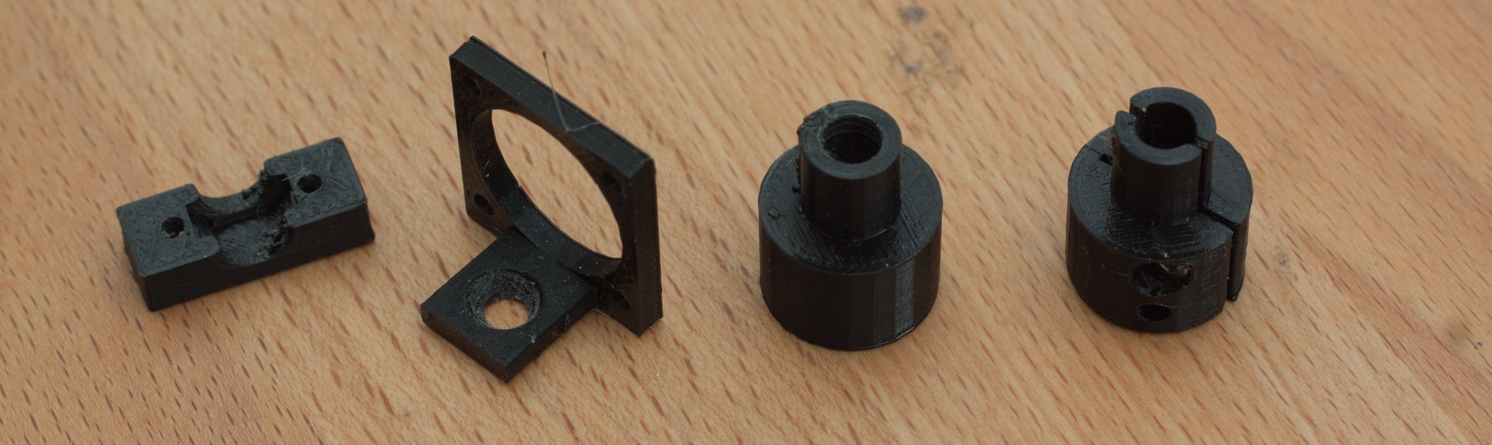
(First-) iterations of various parts.
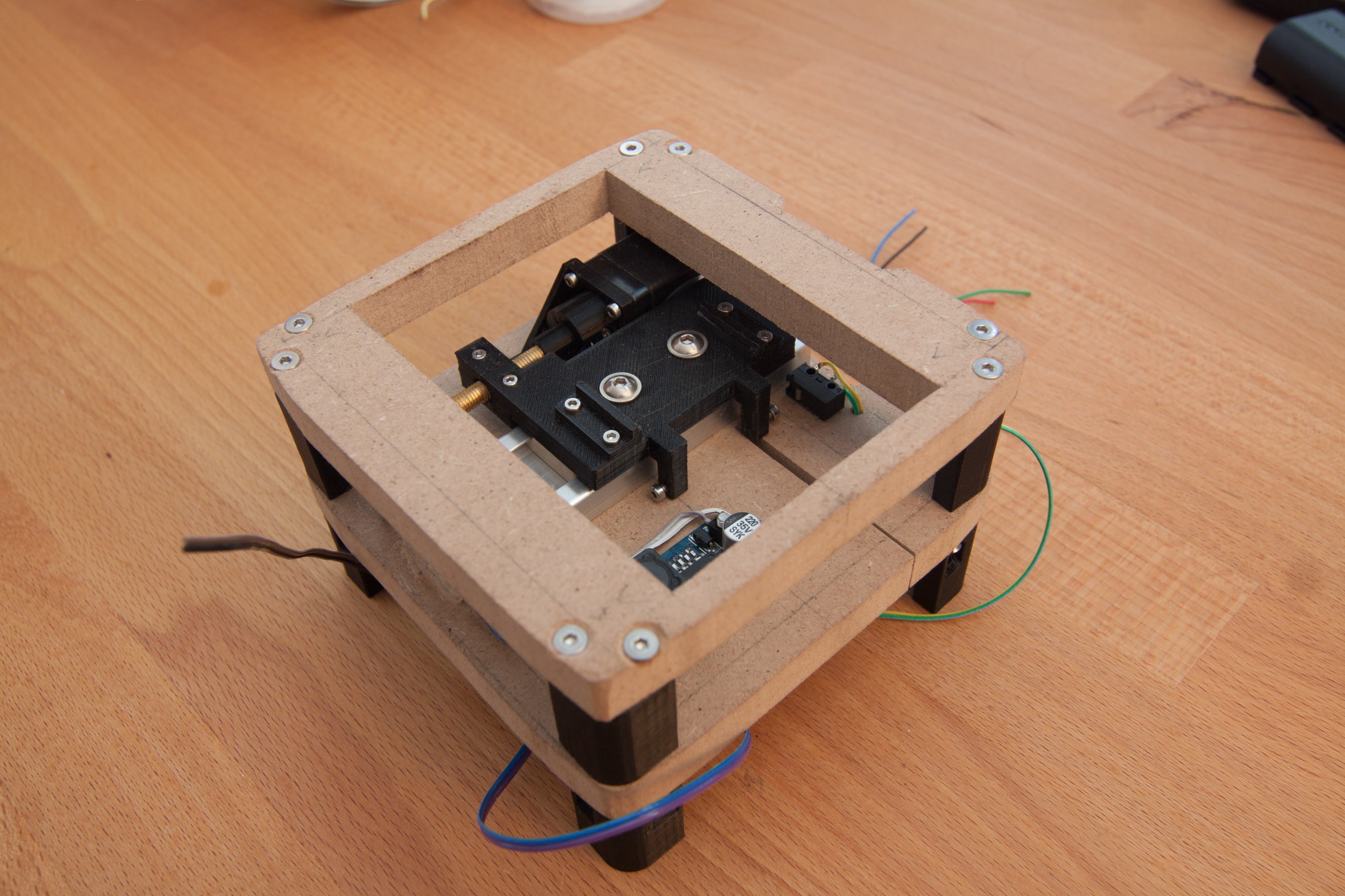
Overview shot of the whole assembly.
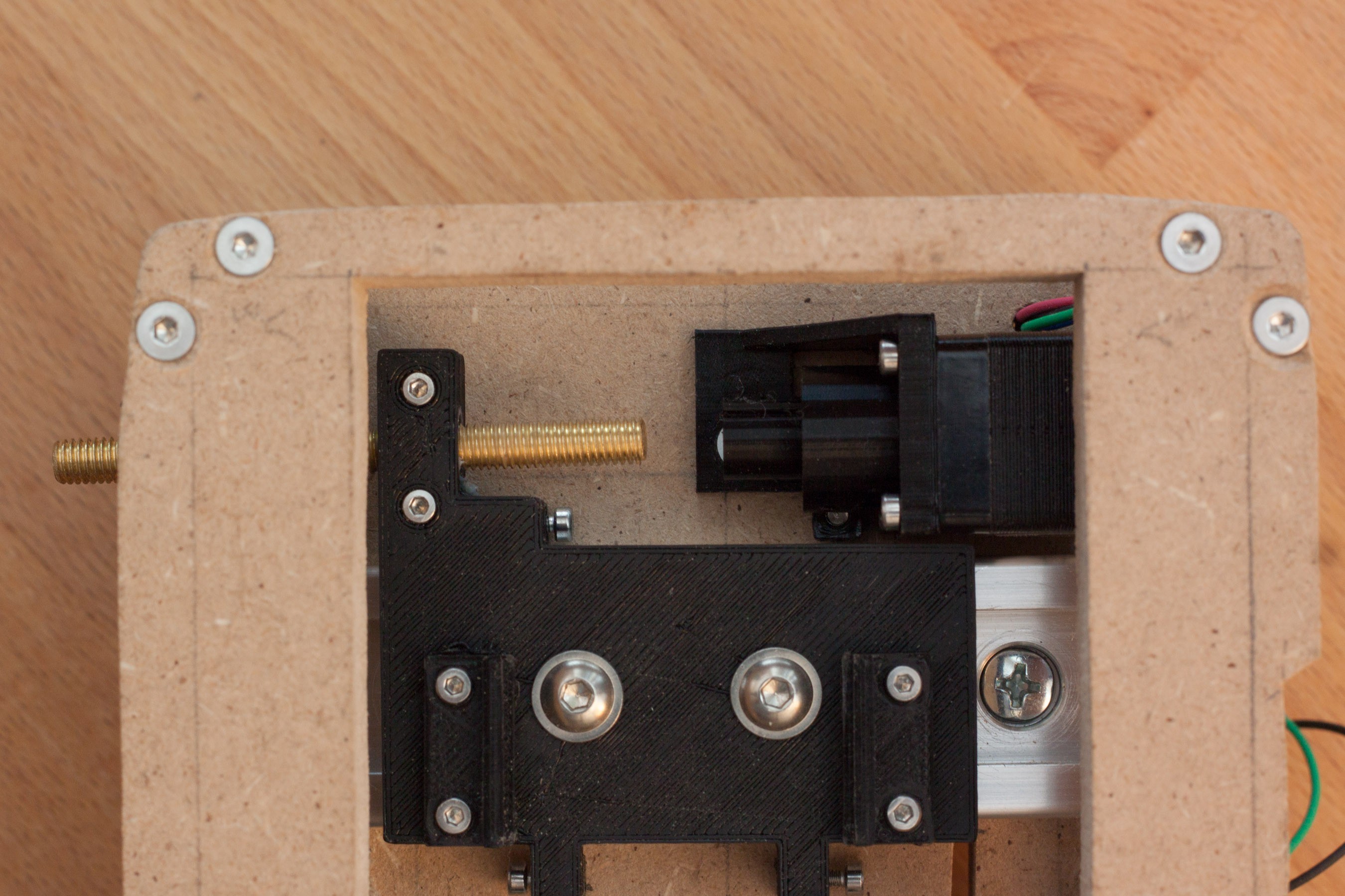
This picture shows the stepper mounting bracket, lead screw assembly, and how the spacers between the mdf plates are fastened.
Also lead screw, stepper motor bracket, and carriage with the two adjusting screws for the endstop switches at the bottom. One half of the mechanical endstops is also visible just below the lead screw and below the coupling.
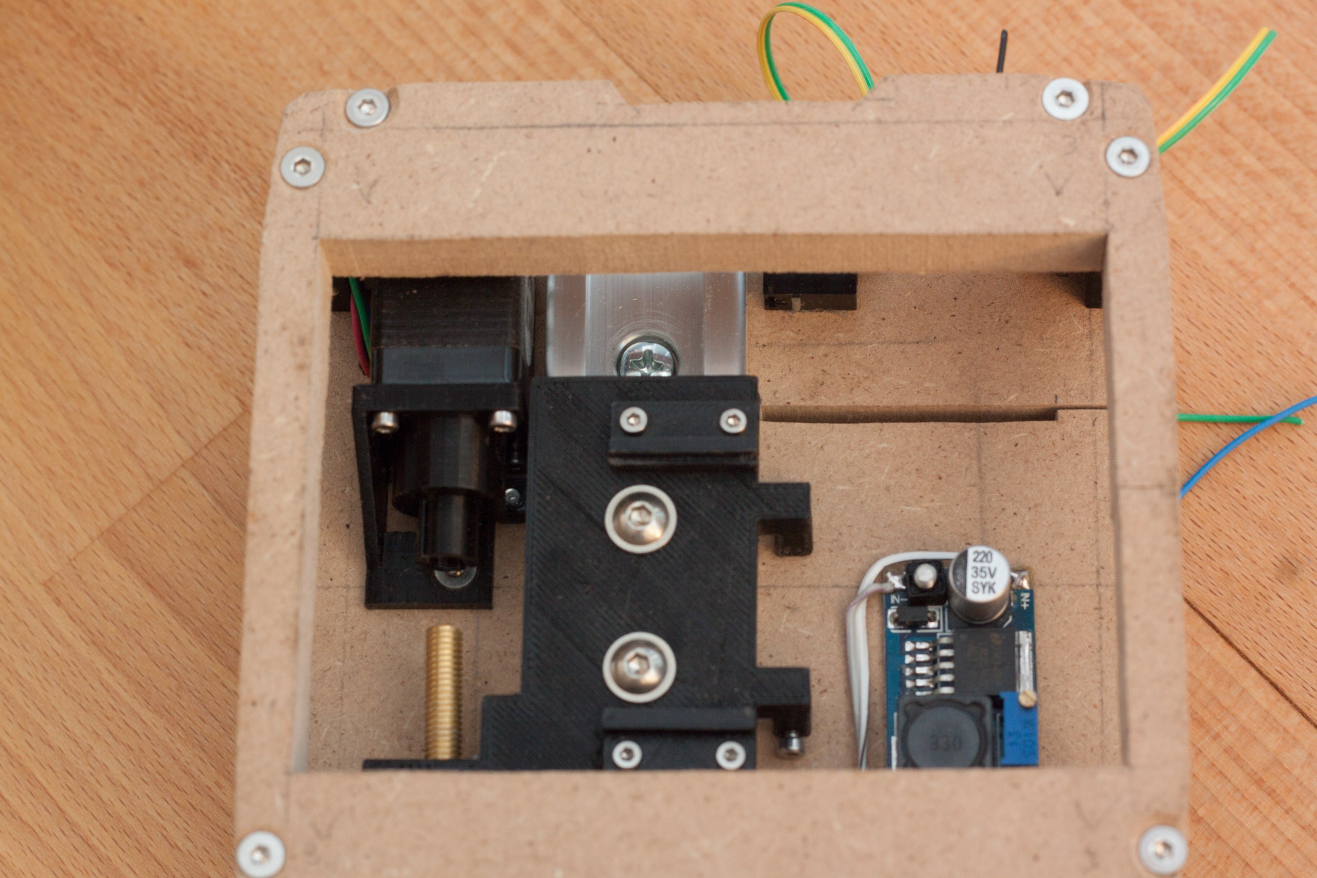
A step-down dc-dc converter was mounted in this area, because there was unused space.
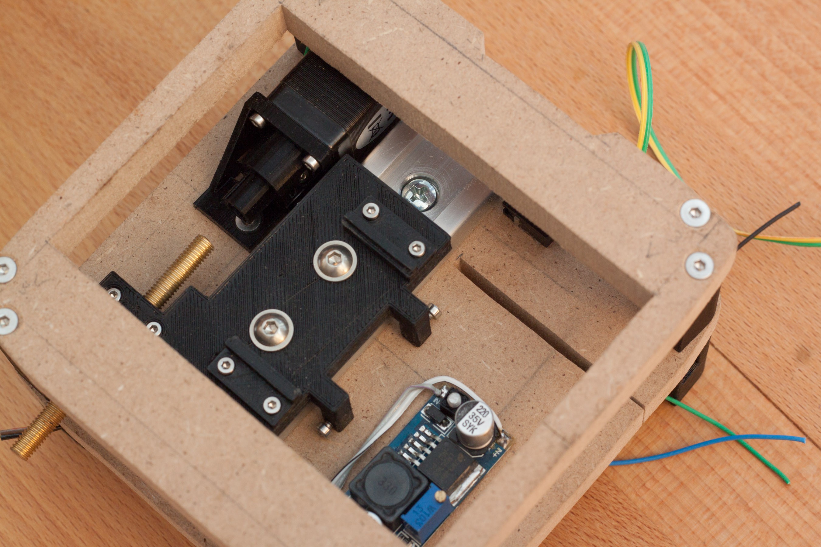
Detail shot of the adjustable endstop switch. The two small pieces on top of the carriage are the mounting for the sensor pcb. They are separate pieces from the carriage, so the carriage is easier to print, which helps to get the critical dimensions right. Another reason is, that the mounting can be changes easily with new designs.
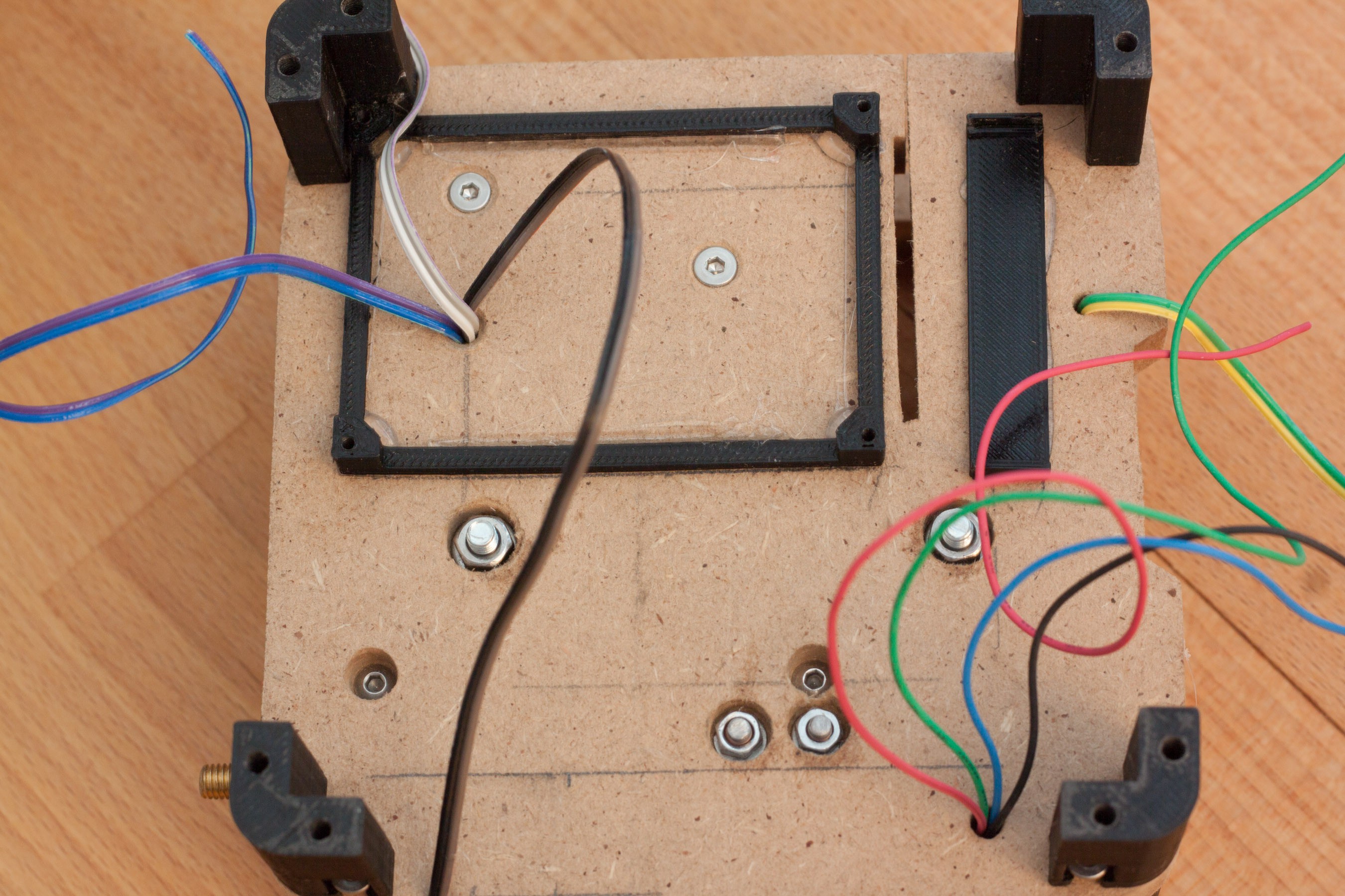
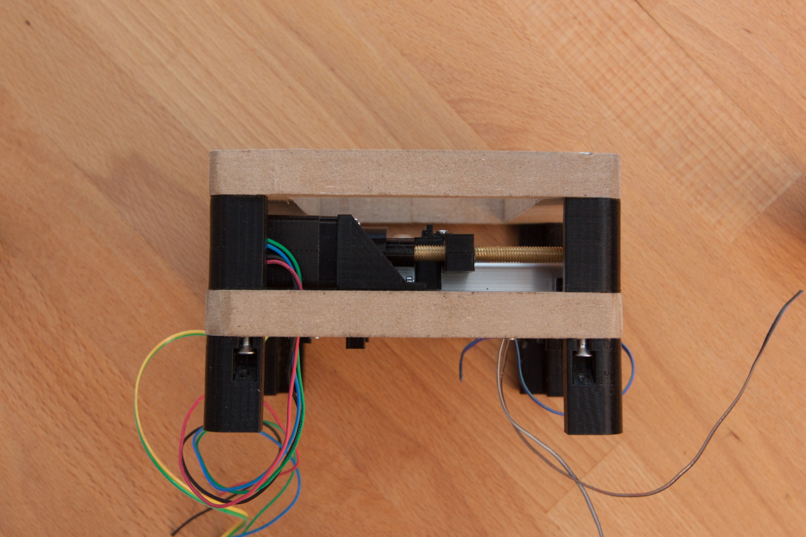
Back Side with cables for endstops, step-down converter, and stepper motor. Counterbores for the screws and nuts are also shown. This is done, so the surface of the mdf plate is plane and it is easy to mount other components on it.
Discussions
Become a Hackaday.io Member
Create an account to leave a comment. Already have an account? Log In.