disasterarchy
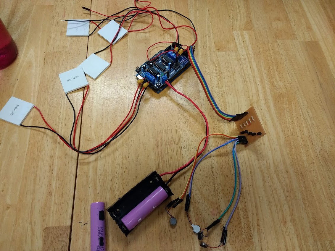
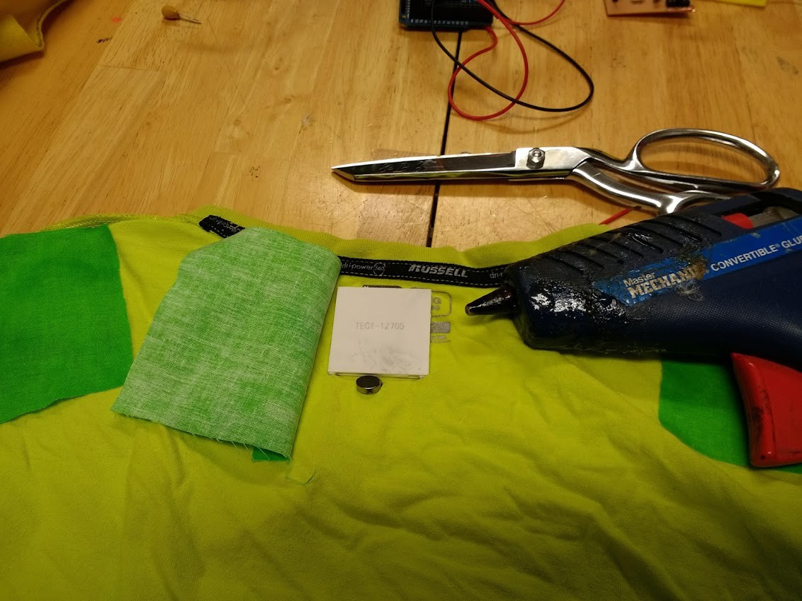
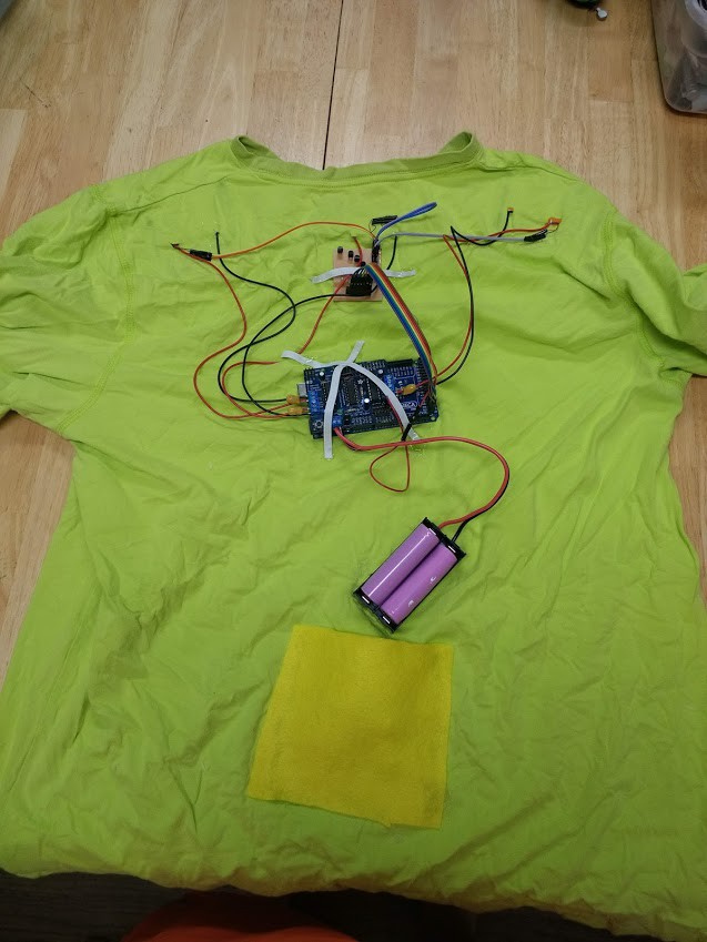
An interface to communicate to users via touch using heat/cold and vibration.
0%
0%
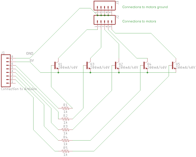
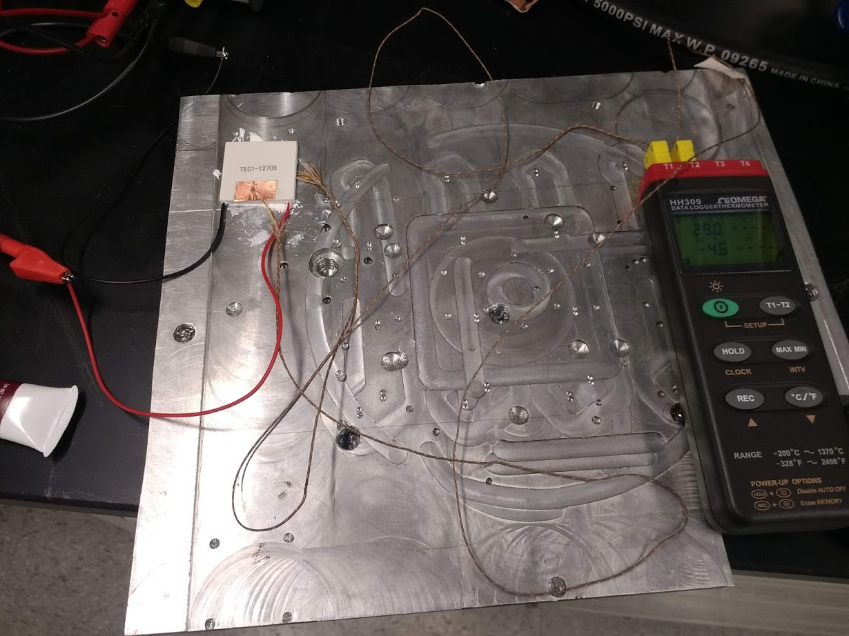
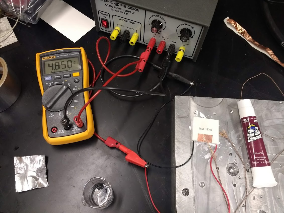
Tactile Tactical Interface
Heat/Cold/Vibration interface for situational awareness for firefighters, police, military, transportation, gaming, etc.
Become a Hackaday.io member
Already have an account? Log in.
Just one more thing
To make the experience fit your profile, pick a username and tell us what interests you.
Pick an awesome username
hackaday.io/
Your profile's URL: hackaday.io/username. Max 25 alphanumeric characters.
Pick a few interests
Projects that share your interests
People that share your interests
 icstation
 cele9999
 hylke44