Close
0%
0%

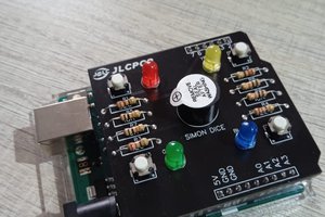
Countdown Timer Blinky

A visual countdown timer, created for Macrofab's Blink an LED design contest.

Similar projects worth following
A visual countdown timer, configurable for 5, 10, 30, and 60 second countdowns.

macroFabBlinky.ino

Arduino firmware

ino - 2.56 kB - 09/06/2018 at 05:41

Download

BlinkyV0.brd

Eagle board file

brd - 55.30 kB - 08/14/2018 at 04:20

Download

BlinkyV0.sch

Eagle schematic

sch - 88.77 kB - 08/14/2018 at 04:20

Download

  • 1 × CR2032 Batteries and Battery Accessories / Batteries
  • 1 × 712-BAT-HLD-001 CR2032 Battery Clip
  • 1 × ATMEGA328P-AN Microprocessors, Microcontrollers, DSPs / ARM, RISC-Based Microcontrollers
  • 1 × ECS-23G 8MHz Crystal
  • 1 × Various resistors and capacitors

  • Entry 1

    Charles Dean Modrich09/06/2018 at 05:26 0 comments

    The boards showed up, and they look great! After a quick test sketch and a fresh battery the blinky is pretty much good to go. 

    It's here!
    The blinky in all of its blurry glory

    Here it is in action: 

    Here's the code:

    #include <avr/sleep.h>          // library for sleep
    #include <avr/power.h>          // library for power control
    
    #include <Adafruit_SleepyDog.h>
    
    #define LED0 5
    #define LED1 4
    #define LED2 2
    #define LED3 A2
    #define LED4 10
    #define SWpin 6
    
    #define J0 7
    #define J1 8
    
    int secondsToCountDown = 5;
    
    void setup() {
      //Initialize the pins and set them low
      pinMode(LED0, OUTPUT);
      pinMode(LED1, OUTPUT);
      pinMode(LED2, OUTPUT);
      pinMode(LED3, OUTPUT);
      pinMode(LED4, OUTPUT);
      digitalWrite(LED0, LOW);
      digitalWrite(LED1, LOW);
      digitalWrite(LED2, LOW);
      digitalWrite(LED3, LOW);
      digitalWrite(LED4, LOW);
    
      pinMode(SWpin, INPUT_PULLUP);
      
      pinMode(J0, INPUT_PULLUP);
      pinMode(J1, INPUT_PULLUP);
    
      //There are two solder junctions available just above the button.
      //This can control how long the timer is set for without the need to reprogram.
      //Make sure to take the battery out to reset the device after setting the jumper!
    
      if (digitalRead(J0) == HIGH && digitalRead(J1) == HIGH) {
        secondsToCountDown = 5;
      }
      if (digitalRead(J0) == HIGH && digitalRead(J1) == LOW) {
        secondsToCountDown = 10;
      }
      if (digitalRead(J0) == LOW && digitalRead(J1) == HIGH) {
        secondsToCountDown = 30;
      }
      if (digitalRead(J0) == LOW && digitalRead(J1) == LOW) {
        secondsToCountDown = 60;
      }


    }
    
    void loop() {
      countDown(secondsToCountDown); //I hope you know what this does
    }
    
    void countDown(byte seconds) {
      if (digitalRead(SWpin) == LOW) { //If the button is pushed, do the thing
        digitalWrite(LED0, HIGH);
        digitalWrite(LED1, HIGH);
        digitalWrite(LED2, HIGH);
        digitalWrite(LED3, HIGH);
        digitalWrite(LED4, HIGH);
        //So really the delay time should be 1000 * seconds / 5, but I think the 
        //crystal frequency is half of what it 'should' be so millis() is thrown off
        //I'll fix the crystal frequency issue later, but in the meantime this'll work
        delay(1000 * seconds / 10);
        digitalWrite(LED4, LOW);
        delay(1000 * seconds / 10);
        digitalWrite(LED3, LOW);
        delay(1000 * seconds / 10);
        digitalWrite(LED2, LOW);
        delay(1000 * seconds / 10);
        digitalWrite(LED1, LOW);
        delay(1000 * seconds / 10);
        digitalWrite(LED0, LOW);
    
      }
      else {
        Watchdog.sleep(1000); //If the button isn't pushed, go to sleep.
        //This is much worse than using a wake interrupt since the device has to wake up
        //every second to see if a button is being pushed, but what are you gonna do
      }
    }

    A few things that can be improved in the future:

    • Actually use the external clock crystal rather than the internal oscillator. (fuses are scary)
    • Modify the circuit board to use pins 2 or 3 for the switch, since apparently those are the only two digital pins with interrupt capability on the 328p-au. Consequently, the chip is forced to use a suboptimal sleep scheme, which is less energy efficient and offers poor responsiveness to a button press. 
    • Use higher resistance values for the current limiting resistors on the leds. As they are, they're probably too bright and so some energy can be saved limiting their intensity.

    In the meantime though I'm pretty sure the battery is going to last a good long while and the timing will be reasonably accurate, so I'm quite happy at the end of the day. 

    Special thanks to MacroFab for the fast and cheap service, without which this project would never have happened. 

  • Entry 0

    Charles Dean Modrich08/14/2018 at 04:24 0 comments

    • Sketched out the basic premise of the device.
    • Crawled Mouser for all the components I thought I'd need
    • Did a bunch of research on how to efficiently run Arduino devices in aggressive low-power modes
    • Obtained the eagle libraries I needed to build the Eagle schematic
    • Built the eagle schematic

    Next I'll work on the external enclosure and button assembly, as well as the firmware in a future update.

View all 2 project logs

Enjoy this project?

Share

Discussions

Similar Projects

Does this project spark your interest?

Become a member to follow this project and never miss any updates