 Pavel
PavelThis is a board that is providing sequencing for the Pilot-1 calculating machine:
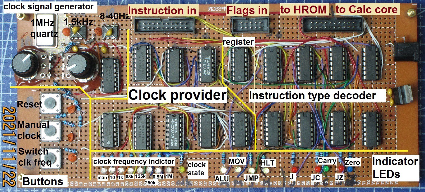
It may be divided into several function blocks:
Instruction type decoder:
It is recognizing 4 types of instructions: ALU, MOV, JMP and HLT:
ALU instructions are for dealing with data modification in registers.
MOV instructions are for moving data between registers.
JMP instructions load address into 74hc163 counter inside the HROM board, thus effectively moving instruction pointer anywhere inside this 16-word instruction ROM; there are 3 kinds of these: unconditional jump, jump on carry, and jump on zero.
HLT instruction is the one that turns off counting, and makes instruction pointer stuck on its address, making machine to be stuck looping just this instruction, halting any further execution. Can only be undone via Reset.
Register:
Carry and Zero flags are saved in 74hc74 dual D-flip-flop chip, to serve as Carry_in for ALU ops, and as flags for conditional jumps.
Clock pulse generation:
Multiple clock frequencies are provided: 1 manual, and 7 auto ( from roughly 10Hz up to 1MHz, which can be seamlessly switched between ). Two slowest frequencies (~10Hz and ~100Hz) are generated using 555 chips and can be smoothly adjusted via potentiometers, while higher 5 frequencies are derived from 1 MHz crystal oscillator and its signal progressively divided by 74hc163 synchronous counter.
Buttons:
Reset, clock pulse, switch frequency.
LEDs:
Indicating:
- main instruction type, and jump subtype;
- C and Z flag value;
- current clock frequency;
- clock signal state;
- Reset signal state.
Preliminary testing results:
For now I tested board all by itself, and it appears to work mostly as expected, but there are some issues:
- I cannot access 5 highest clock speeds provided by crystal oscillator, somehow it switches all the way through right away after I release "change frequency" button (on falling edge), while it supposed to do the switching only when pressed on (rising edge).
- probably related to, and most certainly causes the above problem is the presence of some spurious signals which cause the flipping of flag values in register when clock signal is at high level, and instruction is JUMP (the registers supposed to set/reset only during ALU instruction).
These issues are probably due to coupling of high frequency signals coming from crystal and counter used to divide this signal frequency.
Plans:
In a couple of days I will test this board integrated with HROM and Calculating core as the Pilot-1 machine. I hope the above issues will not be blockers for working of the integrated whole, or will not be too difficult to solve. (Maybe just disconnecting power from crystal will be workable workaround, although in this case highest clock frequency bill only be 1.5 kHz).
Discussions
Become a Hackaday.io Member
Create an account to leave a comment. Already have an account? Log In.