Frank Buss
-
next revision
09/30/2018 at 21:29 • 1 commentI got the boards and parts from Aisler for revision B. After soldering everything, first I measured the voltage regulators. The -5 V was fine, but there was no +10 V. Turns out that I forgot to connect the SHDN pin to VIN. Usually such pins can be left floated, but as the datasheet says, you have to connect this pin for the MCP1804.
After this I tried the sawtooth output again, which had the high frequency noise in the last revision. And the noise was still there.
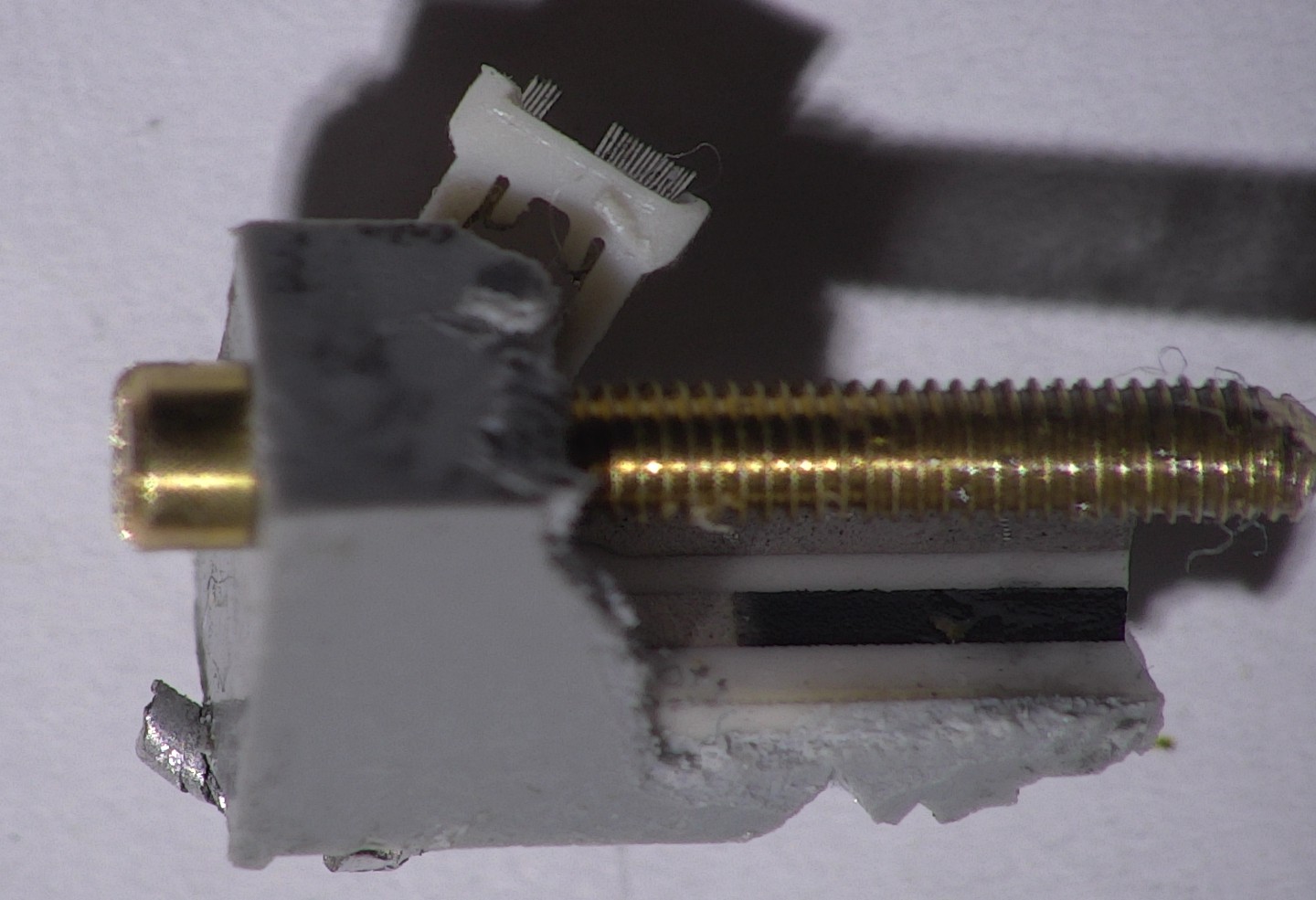
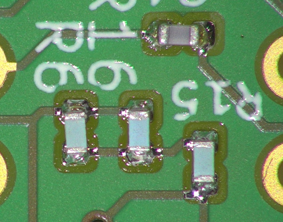
I thought maybe that the trimmers could introduce some noise, if they were wirewound or something like this. So I desoldered them. But the construction looks pretty good, with just two small stripes:
![]()
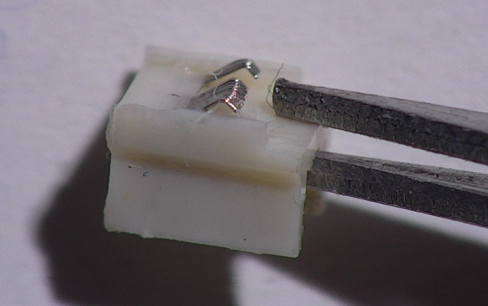
Detail image of the slider:
![]()
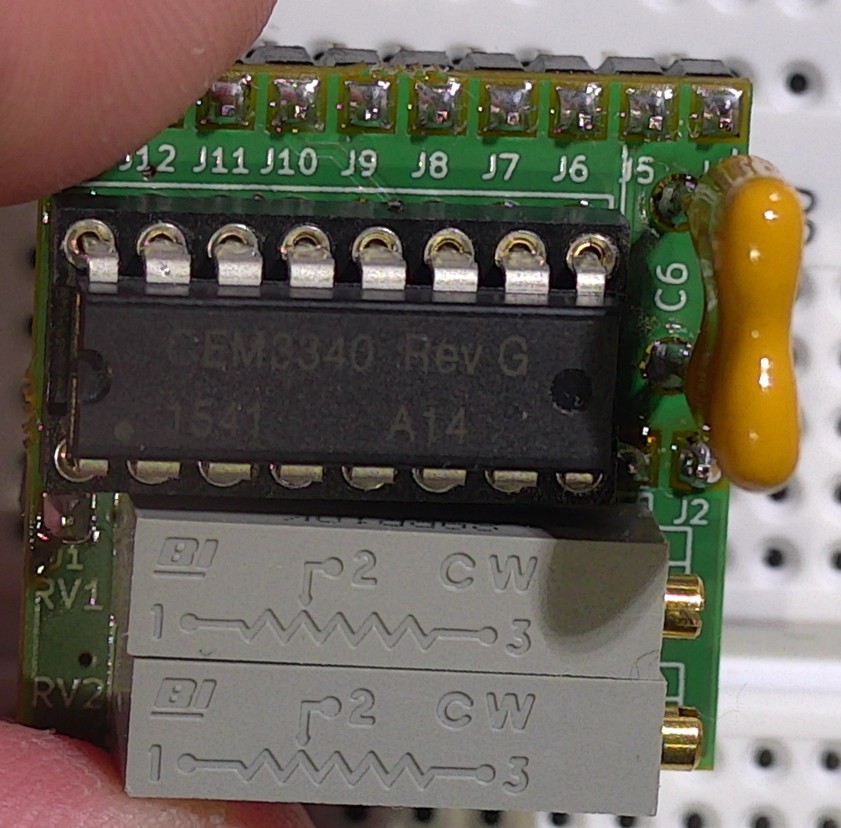
Without the trimmers, the noise was still there. So I lifted the pins of the CEM3340 one by one, starting with pin 1:
![]()
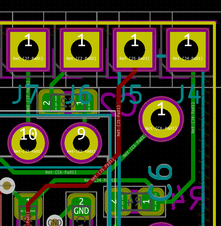
When I reached pin 9, the noise was gone! I guess the layout could be a problem, because the triangle output at pin 10 is right besides pin 9:
![]()
For revision C I moved the capacitor a bit to the right for better distance.
But the datasheet says also, that you should ground pin 9 with a 100 nF capacitor, if not used. So after resoldering everything, I just connected J6 to GND, and the noise was gone as well! Lesson learnt: always read the full datasheet, especially if there are some pins left unconnected.
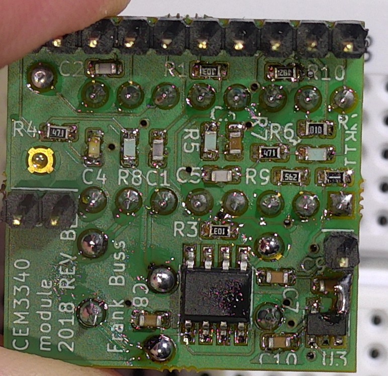
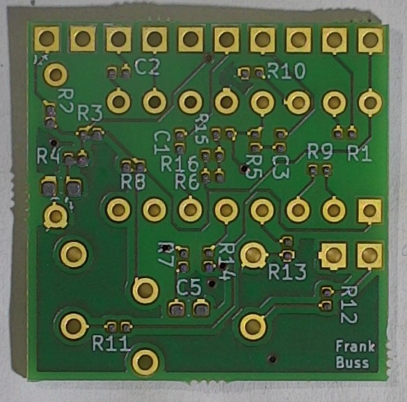
This is how the final version looks like. Top side:
![]()
Bottom side, with the small patch for U3:
![]()
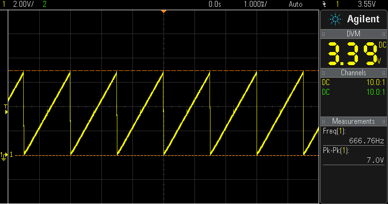
Now the sawtooth looks perfect:
![]()
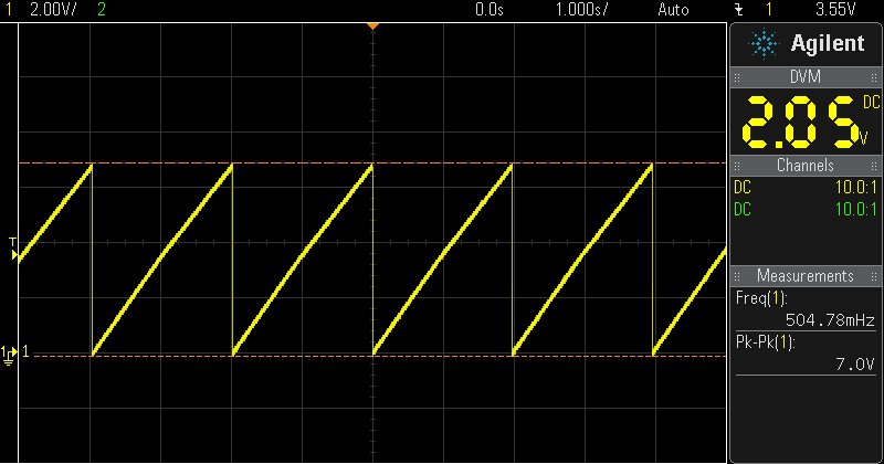
It goes down to 0.5 Hz:
![]()
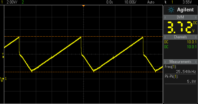
and up to more than 20 kHz, but then the waveform gets a bit distorted:
![]()
But you can't hear this anyway unless you are a bat :-)
-
First revision tested
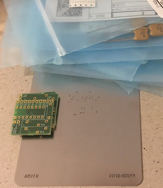
08/26/2018 at 13:27 • 0 commentsI got the boards for the first revision. You can get all you need from AISLER: "beautiful boards", "precious parts" and "stellar stencil" as they call it (which by the way, is an alliteration)
![]()
Unlike other PCB manufacturers, you can order your parts for the board with it, everything which is available at Digikey. This saves some money because you don't have to pay the Digikey shipping fee, and the AISLER shipping is completely free as well.
With the stencil I applied solder paste (not these lead-free rubbish, for project I don't sell, because that's not allowed in Europe, I always use good old leaded paste, this time Chip Quik SMD291AX) :
![]()
Doesn't matter much, if you don't place the parts exactly:
![]()
Usually after the reflow soldering, they are aligned:
![]()
This was the first time I tried my new T962-A reflow oven. Needs some tweaking, because the measured temperature with an external thermocouple on the board was too low, I had to use the lead-free temperature profile for a high enough temperature for the leaded solder paste, but there are some project to hack the firmware of the oven. Will try it soon.
But overall it worked well. This is the board with all SMD parts reflow soldered:
![]()
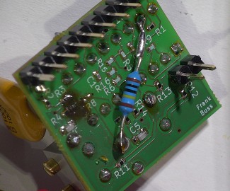
While testing it, I noticed that the high frequency pot didn't work. The reason was a wrong connection of one resistor. Trying to fix it on the board with another SMD resistor didn't work out so well, but I could use a through-hole resistor:
![]()
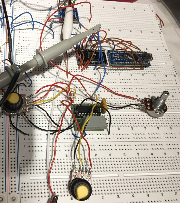
This is the setup on a breadboard:
![]()
At the bottom you can see the CEM3340 module. With one pot I could change the frequency, the other pot was for the duty cycle, which is not needed, if you don't use the square output. Another pot was for the second CV input. If I removed the fixed 360k resistor, the range was amazing: I could change the frequency from less than half a Hz to more than 20 kHz!
The other parts on the board are an Arduino nano and a 16 bit DAC, which I plan to use for a MIDI-2-CV converter. And at the top you can see an OpAmp to buffer the outputs of the CEM3340, because they can't be loaded too much.
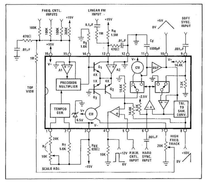
But as you can see in the example circuit diagram of the datasheet, which I've used for my circuit as well:
![]()
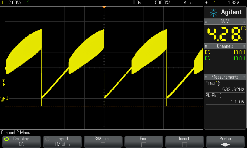
the fixed 360k resistor is connected to the +15V supply, which means the frequency changes if the power supply is not stable or changes. I also have a strange problem with oscillations. This is supposed to be a sawtooth:
![]()
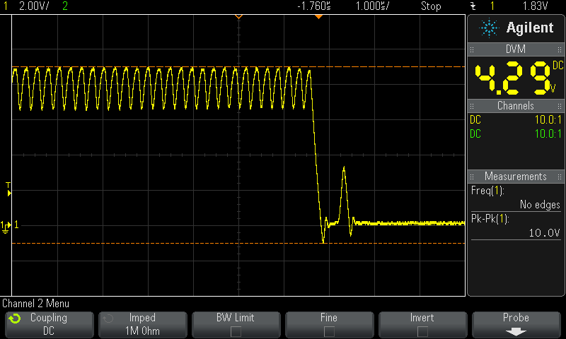
Closeup:
![]()
I guess the problem is that I used the auto-router, so the critical connections like to the 1 nF oscillator capacitor are too long, and there is no nice ground plane.
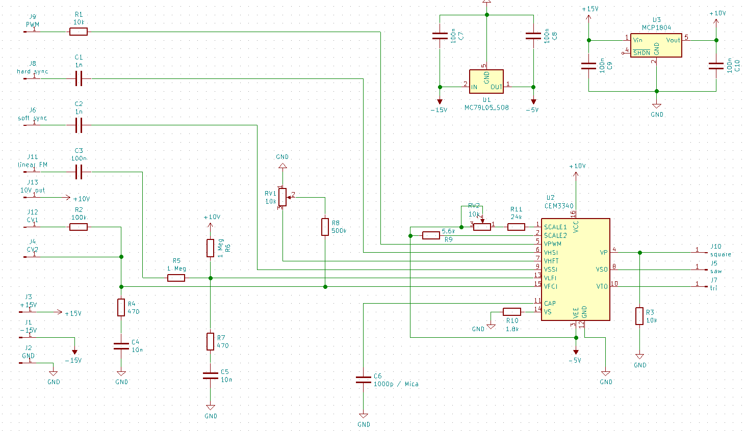
To solve both issues, I added a positive low-drop linear voltage regulator (the chip works fine at 10V as well, so power supply can be still 12V, as it is used for Eurorack modules), and for good measure a negative -5V linear voltage regulator as well. This is the updated circuit diagram:
![]()
I also changed the two CV inputs to one standard input with the 100k resistor. This provides some protection as well. The way the CV input works is that there is an internal OpAmp in the CEM3340 and it keeps the VFCl input at ground level. The VCO is driven by the current into this pin. This means you can add as many inputs as you like, with the resistors to convert the CV voltage to a current, which is then summed.
For more flexibility for the resistors (if you choose higher values, the weighting is lower etc.), I connected the second CV input directly to the chip. In combination with an additional pin to output the new regulated 10V voltage, there are more possibilities how to use.
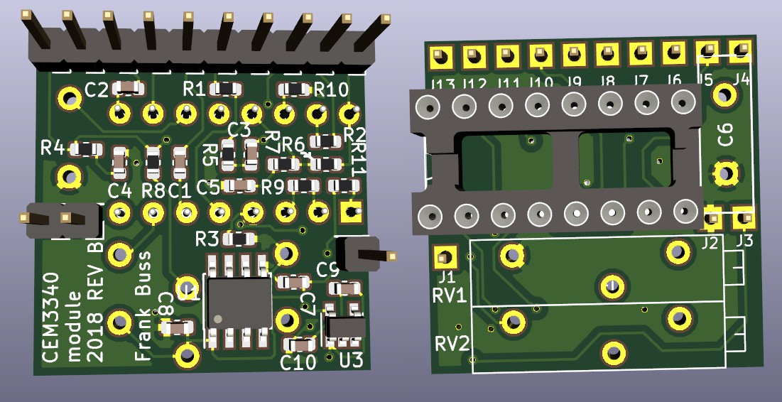
Then I manually routed it this time:
![]()
All 0402 parts are changed to 0603 as well and there is still lots of space on the board. One square inch is sooo big :-) Hopefully this version will work better.
CEM3340 module
all the parts needed to use the voltage controlled oscillator CEM3340