 Colin Alston
Github repo of all the modules being designed:
https://github.com/calston/x-uhf
Thingiverse thing for all the 3D printed parts:
X-UHF is a project to build a low cost RF prototyping system for experimenting in VHF and UHF bands.
Already have an account? Log in.
To make the experience fit your profile, pick a username and tell us what interests you.
Github repo of all the modules being designed:
https://github.com/calston/x-uhf
Thingiverse thing for all the 3D printed parts:
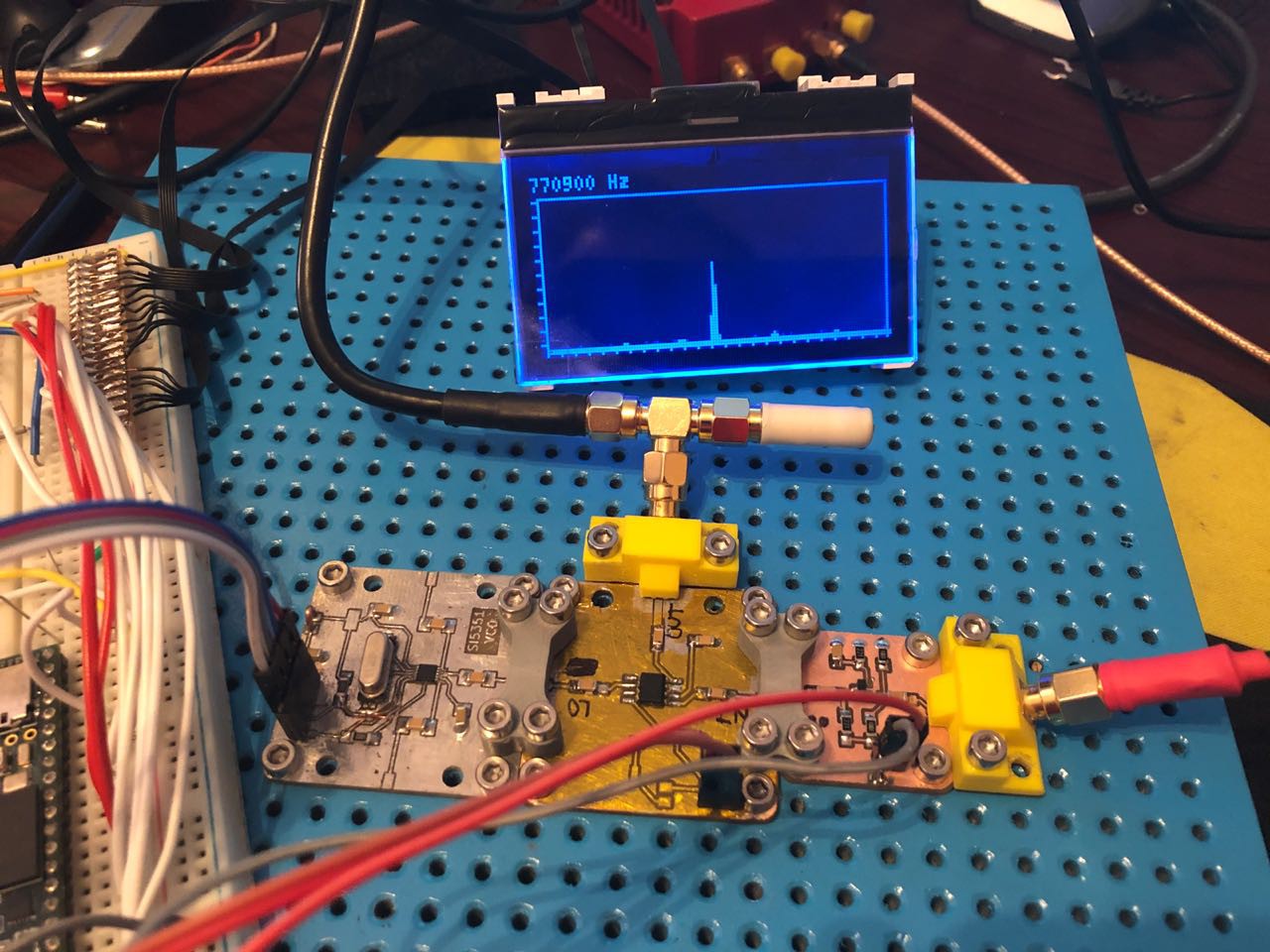
With the modules I have working currently it was enough for a simple FM direct conversion receiver.
As with every other amateur out there this is Yet Another Teensy SDR, and I put the code here https://github.com/calston/x-uhf/tree/master/controller Most of the code is driving the display and user interface.
I haven't had a chance to put some pictures together, but thought I'd talk briefly through this because a lot of the existing SDR code out there is outdated and doesn't make use of the new Teensy Audio library features.
Basically all I did was mix down to a 10khz IF, then use a Biquad filter with a 15Khz highpass stage and 0.7 Q factor. This effectively converts the FM to AM. Then to convert the AM I simply run an abs function on the stream. This does still need further demodulation that I haven't figured out a simple way yet. It should be noted that I have no idea what I'm doing, this entire process was me learning digital filters for the first time.
Ultimately I do NOT want to use I/Q demodulation like everyone else does because this complicates the build not being able to use single ended unbalanced signal paths, and the whole point of this was as a simple demonstration tool that matches the block diagrams in text books.
After a bit of prototyping I accidentally made a working 20dB amplifier, with pretty good frequency response. Only tested up to 100Mhz but flat all the way there.
And so I put together a complete receiver. Yay! Now to get some audio out of it I guess
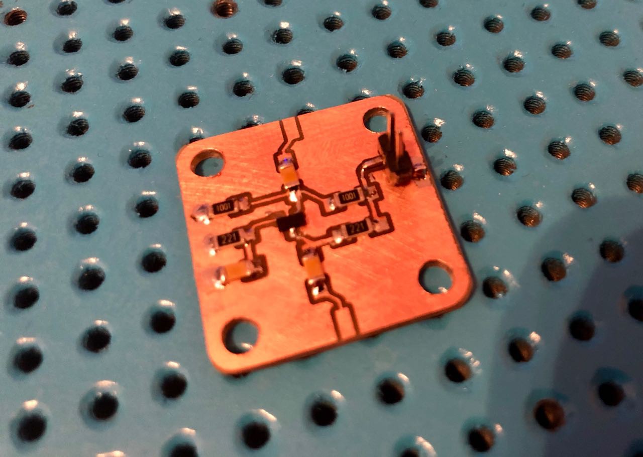
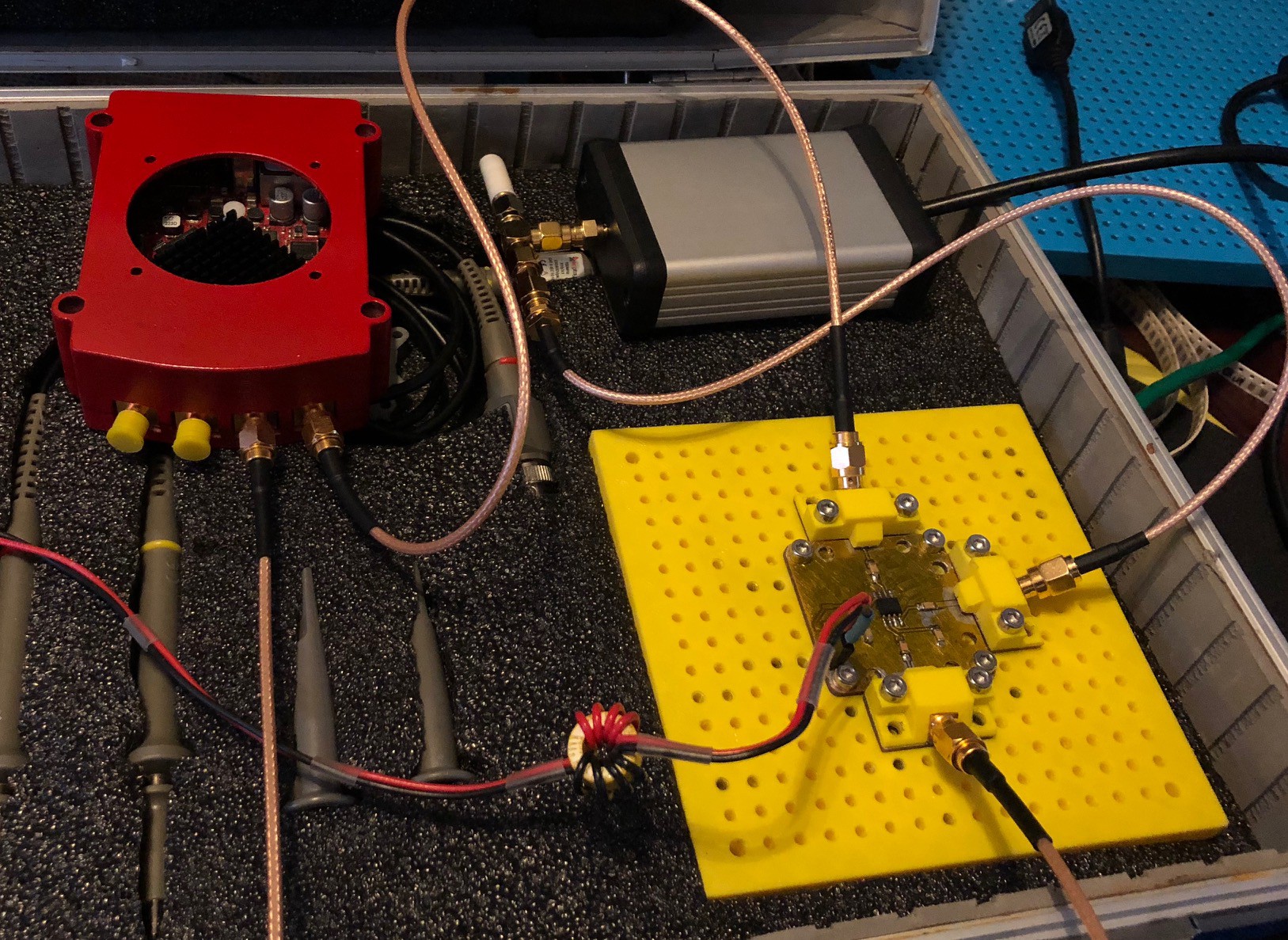
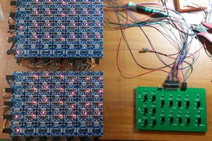
This isn't much of an update on the actual project, but some fun I've been having with the bits I made so far. Since the point of this project is to make RF electronics accessible and fun I decided to build a little 20khz FFT spectrum analyser with a Teensy 3.5.
What's actually displaying of course thanks to the mixer is a 20Mhz signal. With the Si5351 this can go to 200Mhz with some sweeping and filtering, so almost UHF. When I've got funds for another component run I'll look for some higher frequency mixers because the 612 can only take an LO of 200Mhz, so taking 430Mhz down to 20khz is a bit of a big jump.
Of course what we already have here is a radio. Set the LO to the mixer from the VFO module to the frequency of the radio station (minus 20khz) and the teensy gets that signal on it's audio port. From there you can process the signal in software and output it to a speaker on the DAC. Before I start messing with that too much I want to box the Teensy up on a breakout module of its own so I don't have to deal with the breadboard and then add some variable gain amplifier and decoupling transformer / filter.
So that's the next thing on the TODO list - filters and amps! A BFR93 / BD90 low noise amplifier and a simple LM358 op amp for audio or other very low frequency signals.
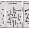
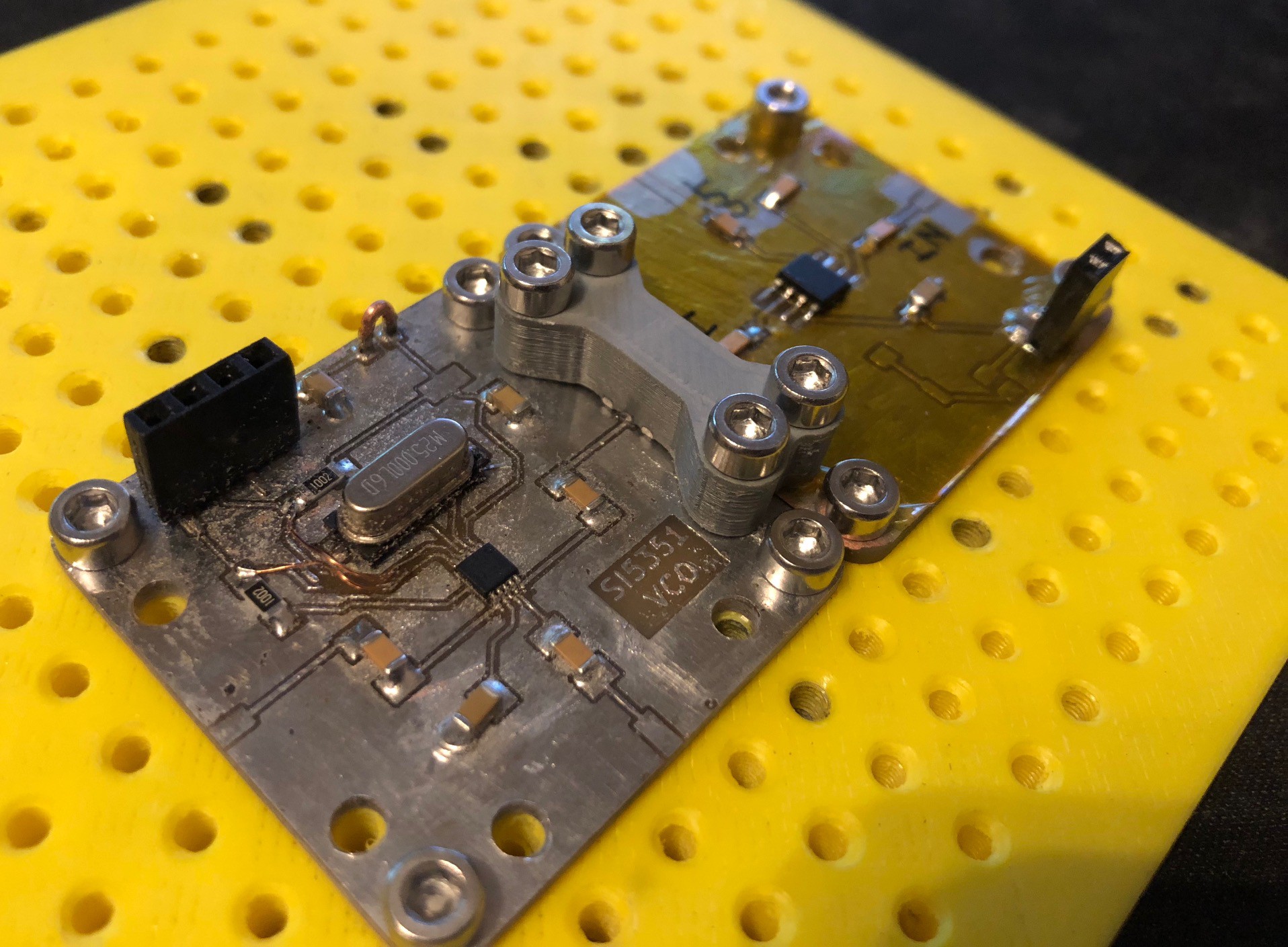
Just a quick photo-op of the completed SI5351 bolted onto a SA612 mixer.
This 5351 design uses a big external crystal because I don't have the tiny SMD ones, but when I do another component order I'll get some of the ones used in the Etherkit 5351 breakout and send the board to a PCB fab. For now this is fine for a test to see if the design makes sense.
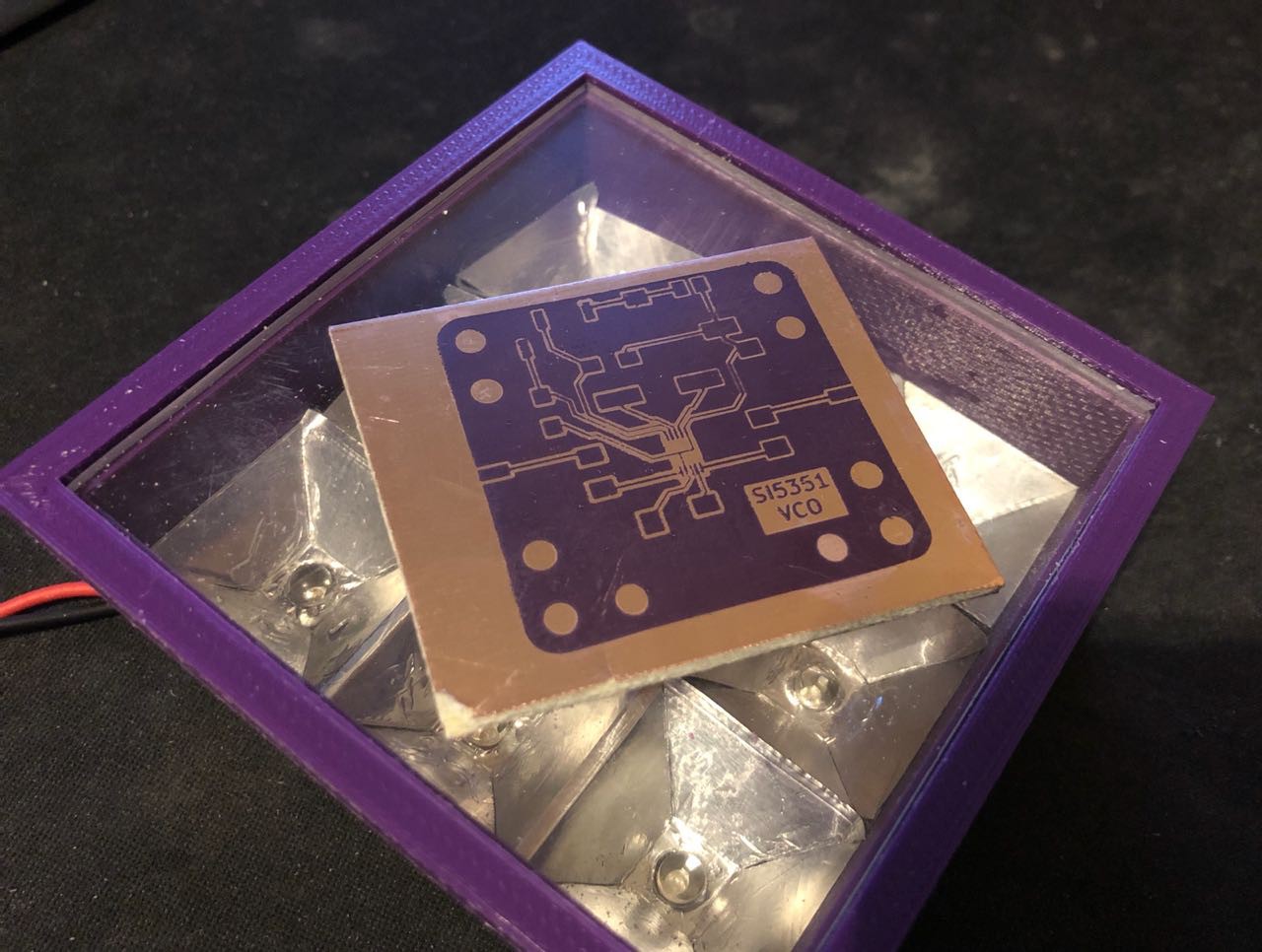
Hoe-lee-cow. I lucked out into a winning recipe. I switched over to a tin foil baking dish to do my Positiv resist spray in, that way I could chuck it in the oven. To give myself a better chance I also modified the layout to remove any sharp transitions between the MSOP pads and their tracks, and bumped them up to 0.3mm. This time I used 3 stacked transparency images for my exposure plate to get a more crisp transfer.
Instead of chucking it in the oven though I set my 3D printer to heat its bed to 70 degrees and left it on there for 20 minutes. Something odd happened though and all the resist spray dried in a big bead in the middle of the board. This could have been contamination but I also wondered if the resist dried too fast instead of being able to spread. So I sanded the board properly with 800 grit paper on a level surface and set it on the printer again at 60 degrees for 45 minutes on a slight angle. This worked absolutely perfectly giving me a totally even surface, so without wasting a second I got it in the UV exposure unit but this time for only 6 minutes, as a test at 10 minutes was way over exposed - I guess I made a more powerful UV box than I had thought.
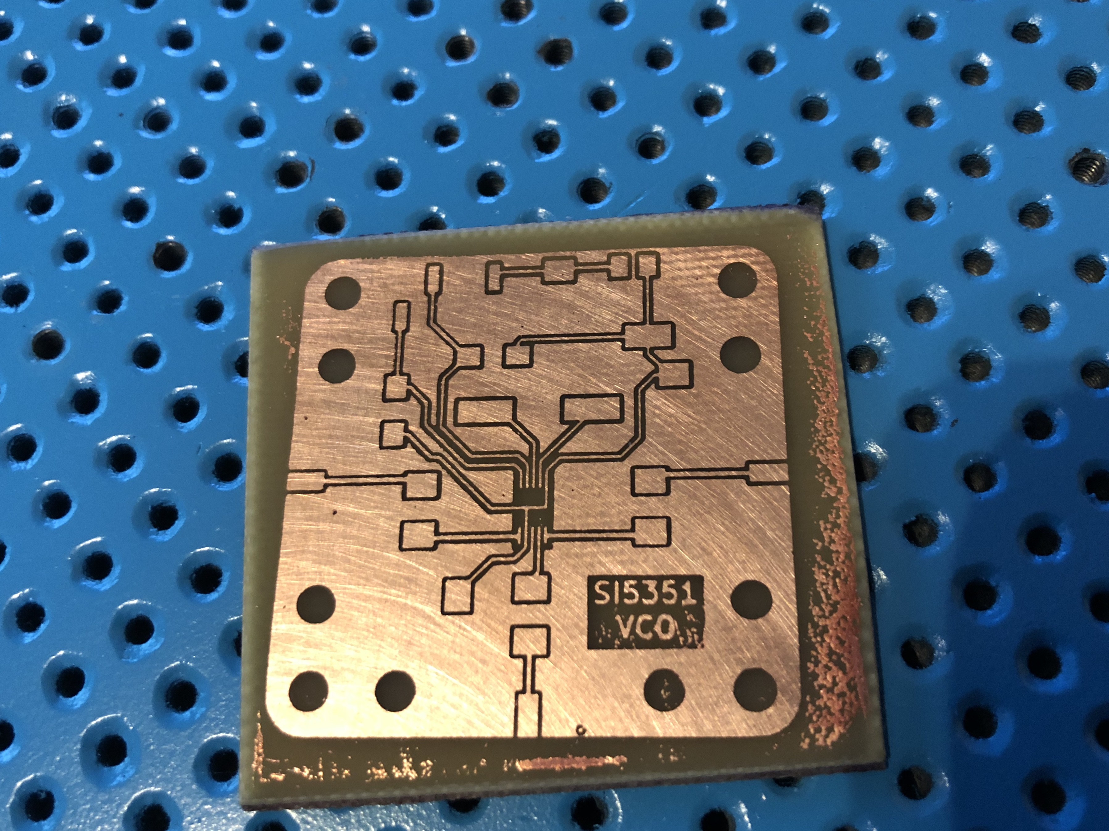
The end result after etching was this. There's a little bit of un-etched copper on the edges but the actual tracks were perfect so I didn't want to risk over etching them. This is about the best PCB I've made ever ever, so yeah this is definitely my process going forward.
Now it's time to tin this board and get some components on it to see where it fails.
The fine traces for the 5351 oscillator required switching to a UV lithography PCB process. So I had to build a quick UV exposure box.
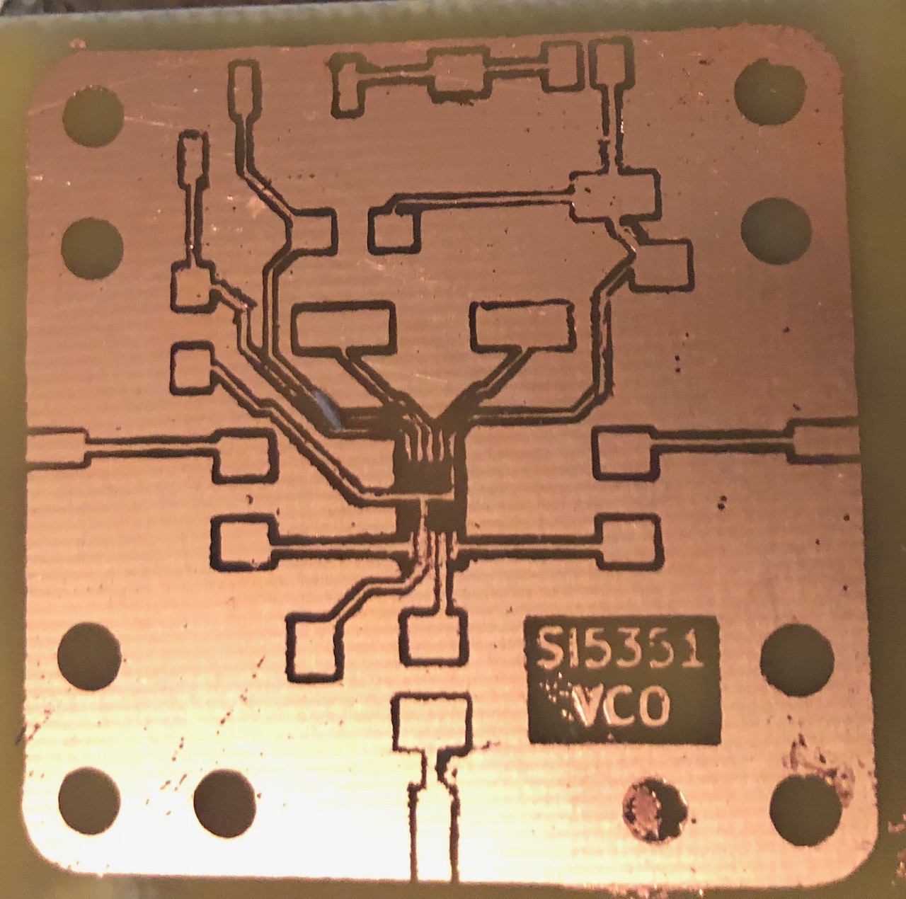
First attempt with 5 hour dry time on the Positiv spray and 10 minute UV exposure worked quite well so I decided to go ahead and etch it.
It seems there was a bit of ghosting on the transparency plate which meant the angled traces got lost, and the channel 1 end launch got lost somehow on the plate so it needs to be reprinted. For the most part this was a pretty encouraging first attempt, UV exposure is definitely the way to go.
I'm going to keep trying to get a test board working before sending anything to a professional fab.
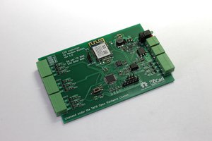
I made the PCB for an SA612 mixer module and assembled the first test build. The only thing missing is the LD1117 regulator so I am just powering it from an external regulated supply.
All seems to be working well, although only tested up to 50Mhz until I build the Si5351 module.
Tons of extra harmonics but thats to be expected with no filtering. Still there was no visible distortion even up to 40Mhz IF with a 10Mhz input signal. Initially I tested with the Redpitaya's function generators and its input in the oscilloscope mode. Unfortunately the spectrum analyser mode doesn't let you turn the outputs on at the same time so I swapped over to an RTL-SDR module to look at the spectrum.
Now to try my hand at UV photoresist PCBs and try get a working VCO with the Si5351
Possibly, I wanted to try and reduce the risk of having a capacitive connection, but my little connectors don't work well at all. I need to get back to this design and tweak some things but I have been busy fleeing to a new country.
With 2 ENIG PCBs pressed together I can't imagine that it would seriously degrade the performance at sub 1 GHz. Maybe the ground contact plane should be larger. It could just be the 50 ohm center conductor, and then the rest of it exposed ground plane. That would certainly be better than just 2 ground conductors.
 Dave's Dev Lab
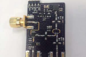
This is really nice! Maybe the board to board connectors could be improved by just having a PCB underneath. Bare PCBs can be ordered from China dirt cheap, and that would make assembly easier.